Transcription
A national laboratory of the U.S. Department of EnergyOffice of Energy Efficiency & Renewable EnergyNational Renewable Energy LaboratoryInnovation for Our Energy FutureMechanism of HydrogenFormation in Solar ParabolicTrough ReceiversL. Moens and D. BlakeNREL is operated by Midwest Research Institute BattelleContract No. DE-AC36-99-GO10337Technical ReportNREL/TP-510-42468February 2008
Mechanism of HydrogenFormation in Solar ParabolicTrough ReceiversL. Moens and D. BlakePrepared under Task No. CP071201National Renewable Energy Laboratory1617 Cole Boulevard, Golden, Colorado 80401-3393303-275-3000 www.nrel.govOperated for the U.S. Department of EnergyOffice of Energy Efficiency and Renewable Energyby Midwest Research Institute BattelleContract No. DE-AC36-99-GO10337Technical ReportNREL/TP-510-42468February 2008
NOTICEThis report was prepared as an account of work sponsored by an agency of the United States government.Neither the United States government nor any agency thereof, nor any of their employees, makes anywarranty, express or implied, or assumes any legal liability or responsibility for the accuracy, completeness, orusefulness of any information, apparatus, product, or process disclosed, or represents that its use would notinfringe privately owned rights. Reference herein to any specific commercial product, process, or service bytrade name, trademark, manufacturer, or otherwise does not necessarily constitute or imply its endorsement,recommendation, or favoring by the United States government or any agency thereof. The views andopinions of authors expressed herein do not necessarily state or reflect those of the United Statesgovernment or any agency thereof.Available electronically at http://www.osti.gov/bridgeAvailable for a processing fee to U.S. Department of Energyand its contractors, in paper, from:U.S. Department of EnergyOffice of Scientific and Technical InformationP.O. Box 62Oak Ridge, TN 37831-0062phone: 865.576.8401fax: 865.576.5728email: mailto:reports@adonis.osti.govAvailable for sale to the public, in paper, from:U.S. Department of CommerceNational Technical Information Service5285 Port Royal RoadSpringfield, VA 22161phone: 800.553.6847fax: 703.605.6900email: orders@ntis.fedworld.govonline ordering: http://www.ntis.gov/ordering.htmPrinted on paper containing at least 50% wastepaper, including 20% postconsumer waste
Executive SummarySolar parabolic trough systems for electricity production are receiving renewed attention, and new solarplants are under construction to help meet the growing demands of the power market in the WesternUnited States. The growing solar trough industry will rely on operating experience it has gained over thelast two decades. Recently, researchers found that trough plants that use organic heat transfer fluids(HTF) such as Therminol VP-1 are experiencing significant heat losses in the receiver tubes. The causehas been traced back to the accumulation of excess hydrogen gas in the vacuum annulus that surroundsthe steel receiver tube, thus compromising the thermal insulation of the receiver. The hydrogen gas isformed during the thermal decomposition of the organic HTF that circulates inside the receiver loop, andthe amount of hydrogen getters installed inside the annulus in the past has proven to be insufficient forcontrolling the hydrogen build-up over the lifetime of the receivers. This paper will provide an overviewof the chemical literature dealing with the thermal decomposition of diphenyl oxide and biphenyl, thetwo constituents of Therminol VP-1.iii
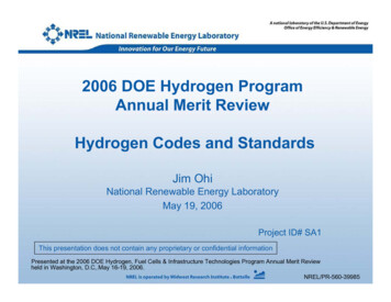
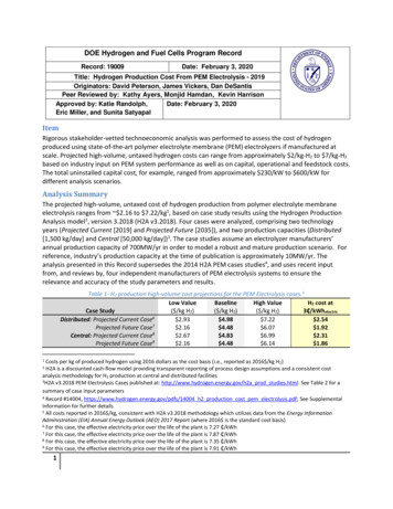
ContentsExecutive Summary. iiiContents . ivList of Figures . ivAcronyms and Abbreviations . ivIntroduction. 1Thermal Decomposition of Biphenyl and DPO. 2Thermal Decomposition of DPO/Biphenyl Mixtures . 4Other Possible Sources of Hydrogen in Solar Receivers. 6Alternative Organic HTF . 7Conclusions. 7References. 8List of FiguresFigure 1. Components of Therminol VP-1 and Dowtherm A.1Figure 2. Cleavage of biphenyl by hydrogen atom.3Figure 3. Radical-induced formation of polyphenyls and hydrogen .3Figure 4. Cleavage reactions of DPO .4Figure 5. Aromatic compounds formed during thermal breakdown of Dowtherm A.4Figure 6. Proposed mechanism for thermal breakdown of DPO/biphenyl mixtures (Ph-O-Ph DPO; Ph-Ph biphenyl; Ph C6H5 phenyl radical) .5Figure 7. Catalytic conversion of DPO into dibenzofuran .6Acronyms and AbbreviationsDPOGPCHCFHTFR&Ddiphenyl oxide (DPOgel permeation chromatography (GPC)heat collection elements (HCE)heat transfer fluids (HTF)research and developmentiv
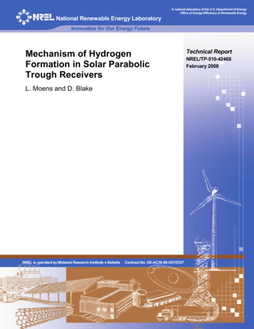
IntroductionSolar parabolic trough systems for electric power production have been operating in the western UnitedStates for over two decades, and new trough plants are currently under construction to help meet thegrowing demands of the power market.[1] These solar plants consist of large fields of modular parabolictrough collectors that capture and focus the sensible solar heat radiation onto a linear receiver tube thatis placed in the focal line of the parabolic trough collectors. A heat transfer fluid (HTF) circulatesthrough the receiver tube and transports the thermal energy to a heat exchanger system in a power blockwhere high-pressure superheated steam is generated. This steam is then used to drive a steamturbine/generator to produce electricity. The receiver tube loop that runs through the solar field is madeup of a modular series of heat collection elements (HCE). Each HCE is composed of a steel tube thatcontains the HTF and an outer glass tube that maintains a vacuum around the hot steel tube. Thisvacuum annulus serves as a thermal insulator while allowing for maximum absorption of the solarthermal radiation by each HCE.Researchers have tested several types of heat transfer fluids in solar fields, e.g., mineral oils, silicones,heavy aromatic oils, and molten salts. Among these, the most cost-effective and most practical organicoil is that composed of a eutectic mixture of diphenyl oxide (DPO, or (di)phenyl ether) and biphenyl,which is better known under the trademark names of Therminol VP-1 or Dowtherm A.[2] The eutecticformulation is composed of 73.5% DPO and 26.5% biphenyl, and has a pour point of 12 C (Figure 1).Obiphenyldiphenyl oxideFigure 1. Components of Therminol VP-1 and Dowtherm AIn spite of the relatively low boiling point of this oil (257 C) it has been used successfully incommercial solar trough plants at operating temperatures as high as 400 C for many years. Yet, eventhough this has led to very reliable and continuous power production for two decades, recentobservations in several solar fields have revealed significant heat losses in a large number of HCEmodules. These thermal losses have been attributed to the slow permeation of traces of hydrogen gasthrough the steel tube wall into the vacuum annulus of several HCE modules, thereby compromising thethermal insulation capacity of the annulus.Since the construction of the first solar trough systems two decades ago, it has been common practiceamong manufacturers of receiver tubes to incorporate so-called “hydrogen getters” inside the vacuumspace of each HCE. These absorb any traces of hydrogen gas that might be formed over time as a resultof thermal degradation of the HTF. Recent observations, however, indicate that the long-term exposureof the organic HTF to 400 C temperatures can lead to hydrogen pressures that exceed the gas-absorbingcapacity of the hydrogen getters, thereby causing the significant heat losses that are currently observedin several solar trough plants.This problem is gaining considerable importance as the trough industry is examining new technologiesto drive the cost of electricity down. These include thermal energy storage to increase the efficiency of1
current as well as future plant designs. In an effort to better understand the causes of the hydrogen gasformation and also to develop possible strategies for mitigating the gas build-up, this paper presents areview of the most relevant chemical and patent literature relating to the thermal decomposition ofbiphenyl and diphenyl oxide. Our intention is to gather literature data that support the notion that thehydrogen formation proceeds at temperatures around 400 C as a result of thermal degradation of theorganic HTF.Thermal Decomposition of Biphenyl and DPOSince the 1930s researchers have known that the thermal decomposition of biphenyl and DPO above400 C results in the formation of tar-like materials with very high melting points (ca. 200 C) that werethen touted as thermally stable heat transfer fluids.[3, 4] At that time, the composition of the thermalproduct mixture could not be determined due to the lack of appropriate analytical tools.During the early 1960s, more details became available regarding the thermal decomposition of purebiphenyl at 425 C as this compound was regarded as a potentially useful coolant for nuclear reactors.This temperature was found to be sufficient to cause pyrolytic decomposition with formation of agaseous mixture that contained hydrogen in addition to carbon monoxide and C1-C3 hydrocarbons.[5, 6]The reaction mixture also contained aromatic hydrocarbons such as benzene, terphenyl, andquaterphenyls. The formation of these polyphenyls clearly indicated that polymerization of the phenylgroups plays a significant role in the pyrolysis of biphenyl. Shortly thereafter, two significant studieswere published wherein Dowtherm A was investigated as a working fluid for potential use in Rankinecycle power systems.[7, 8]. This work showed that circulating this fluid in a test loop kept at 700 F(371 C) for 10,000 hours resulted in the measurable build-up of gaseous products above the fluid, whichagain included hydrogen. In addition, aromatic degradation products such as benzene, phenol, andterphenyls were identified among the reaction products. Considering that the Dowtherm A sold today israted for operating temperatures as high as 400 C, it appears that other factors may have caused thedegradation. As we will discuss later, the presence of impurities in the fluid may have been the culpritBecause of the challenges associated with measuring thermal decomposition rates at 400-450 C,Proksch et al. conducted a systematic kinetic study of the thermal decomposition of pure biphenyl understrict control of the reaction conditions.[9] They found that the careful exclusion of oxygen from thepyrolysis reactor and following the kinetics for thermal decomposition of 1% of the biphenyl samplewere the keys to obtaining consistent results. Because the thermal decomposition of biphenyl at 400 Cwas considered too slow for a practical kinetic study in the laboratory, the thermal decomposition studywas carried out at temperature increments between 420 C and 465 C. At 1% conversion of thebiphenyl the formation of secondary reaction products was avoided and a rate expression for the initialthermal degradation could be derived as a function of temperature using a first-order kinetics approach(Eq. 1):log V 20.59 – (15,770/T)(Eq. 1)where V is the rate of the pyrolysis in %/h for low conversions of liquid biphenyl, and T is thetemperature (K). Assuming first-order kinetics, this rate expression can be transformed into Equation 2:log k 15.03 – (15,770/T)2(Eq. 2)
wherein k is the first-order rate of the pyrolysis in s-1. Using this approach, an Arrhenius activationenergy of 302 kJ/mol (72.1 kcal/mol) was derived. Analysis of the pyrolysis mixture revealed theformation of hydrogen gas, and a mixture of benzene, terphenyl, and quaterphenyl isomers.Interestingly, the concentration of benzene in the aromatic fraction increased from less than 5% at 420 Cfor 150 h, to 23% at 465 C in 6 h, thereby clearly demonstrating the rapid breakdown of biphenyl withina relatively small temperature range above 420 C.The cleavage of the strong carbon-carbon single bond in biphenyl was also of great interest to the fossilfuel industry since this aromatic structure is common to some of the most thermally stable compounds incoal and petroleum-derived aromatic streams. Extensive studies during the 1990s demonstrated thatheating a mixture of biphenyl and alkanes at 450 C resulted in the rapid thermal decomposition of thearomatic compound.[10] The key step in this process is the breakdown of the alkane that releases highlyreactive hydrogen atoms that
Therminol VP-1. are experiencing significant heat losses in the receiver tubes. The cause has been traced back to the accumulation of excess hydrogen gas in the vacuum annulus that surrounds the steel receiver tube, thus compromising the thermal insulation of the receiver. The hydrogen gas is formed during the thermal decomposition of the organic HTF that circulates inside the receiver loop .