Transcription
Ulna Nail 2 Systemwith Tip-LocTM TechnologySurgical Technique
Acumed is a global leader of innovativeorthopaedic and medical solutions.We are dedicated to developing products, servicemethods, and approaches that improve patient care.Acumed Ulna Nail 2 SystemDesigned in conjunction with Roy Sanders, MD, the Acumed Ulna Nail 2 includes three naildiameters and seven length options, power reamers and carbon fiber radiolucent targetingguides to streamline the procedure, threaded holes within the nail, headless hexalobe screwsto help minimize soft-tissue irritation, and the option to lock the nail distally providing additionalfixation within the canal.The Ulna Nail 2 must be used in conjunction with the Acumed Fibula and Forearm Nail(FFN) 2 Base Set, which contains universal instrumentation to implant the Ulna Nail 2,Fibula Nail 2, and screws.Indications for Use:The Acumed Fibula and Forearm Nail 2 System is intended for fixation of fractures andosteotomies of the fibula and ulna, including fractures where the medullary canal is narrow orflexibility of the implant is paramount.DefinitionWarningIndicates critical information about a potential serious outcome to the patient or the user.CautionIndicates instructions that must be followed in order to ensure the proper use ofthe device.NoteIndicates information requiring special attention.
Acumed Ulna Nail 2 System Surgical TechniqueTable of ContentsUlna Nail 2 System Features . . . . . . . . . . . . . . . . . . . . . . . . . . . . . . . . . . . . . . . . . . . . . . . . . . . . . . 2Instrument Overview . . . . . . . . . . . . . . . . . . . . . . . . . . . . . . . . . . . . . . . . . . . . . . . . . . . . . . . . . . . . . 6Surgical Technique Overview . . . . . . . . . . . . . . . . . . . . . . . . . . . . . . . . . . . . . . . . . . . . . . . . . . . . . 8Surgical Technique . . . . . . . . . . . . . . . . . . . . . . . . . . . . . . . . . . . . . . . . . . . . . . . . . . . . . . . . . . . . 10Ulna Nail 2 Surgical Technique . . . . . . . . . . . . . . . . . . . . . . . . . . . . . . . . . . . . . . . . . . . . . . 10Ulna Nail 2 Removal Technique . . . . . . . . . . . . . . . . . . . . . . . . . . . . . . . . . . . . . . . . . . . . . . 30Ordering Information . . . . . . . . . . . . . . . . . . . . . . . . . . . . . . . . . . . . . . . . . . . . . . . . . . . . . . . . . . 34
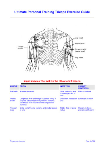
Acumed Ulna Nail 2 System Surgical TechniqueUlna Nail 2 System FeaturesComprehensive SystemThe Acumed Ulna Nail 2 is designed to address simple, transverse, and short oblique fractures as well as osteotomies of the ulna.The Ulna Nail 2 includes: 21 nails offered in three diameters and seven lengthsincluding a short 120 mm nail to address proximalolecranon fracturesPower reamers and carbon fiber radiolucent targetingguides to streamline the procedure Threaded holes within the nail that engage the interlockingscrewsHeadless hexalobe screws aimed to minimize soft-tissueirritationOption to lock the nail distally, providing additional fixationwithin the canalThe Ulna Nail 2 must be used in conjunction with the Acumed Fibula and Forearm Nail 2 Base Set, which contains universalinstrumentation to implant the Ulna Nail 2, Fibula Nail 2, and screws.Note: All nail tail diameters are 6.35 mm3.0 mm Ulna Nail 2120 mm (4011-3012N-S)170 mm (4011-3017N-S)190 mm (4011-3019N-S)210 mm (4011-3021N-S)230 mm (4011-3023N-S)250 mm (4011-3025N-S)270 mm (4011-3027N-S)3.6 mm Ulna Nail 2120 mm (4011-3612N-S)170 mm (4011-3617N-S)190 mm (4011-3619N-S)210 mm (4011-3621N-S)230 mm (4011-3623N-S)250 mm (4011-3625N-S)270 mm (4011-3627N-S)4.0 mm Ulna Nail 2120 mm (4011-4012N-S)170 mm (4011-4017N-S)190 mm (4011-4019N-S)210 mm (4011-4021N-S)230 mm (4011-4023N-S)250 mm (4011-4025N-S)270 mm (4011-4027N-S)2Ulna Nail 2implants accept: 3.5 mm HeadlessHexalobe Screws 3.5 mm NonlockingHexalobe Screws
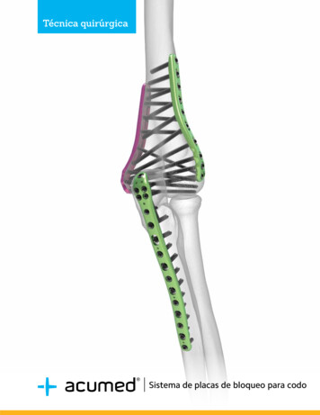
Acumed Ulna Nail 2 System Surgical TechniqueUlna Nail 2 System Features [continued]Implant FeaturesTapered/Offset Nail TipTapered and offset nail tip may aid incrossing the fracture siteFixed-Angle ConstructAll screw holes are threaded to providea fixed-angle construct. Posterior/anterior screws target the coronoid andolecranon processesLow-Profile Screws3.5 mm Headless Hexalobe Screws are low-profile,and are intended to help minimize soft-tissueirritationScrews3.5 mm Nonlocking Hexalobe (8–65 mm) and 3.5 mm Headless Hexalobe(12–65 mm) Screws are both included in the system. The 3.5 mm HeadlessHexalobe Screws lock into the threaded holes within the nail and areintended to create a low-profile construct to help minimizesoft-tissue irritation.Optional End CapsEnd caps assist in limiting ossification over the end of the nail, makingthe nail threads easier to engage if removal is desired. End caps alsoallow surgeons to create an intermediate nail length while adjusting foranatomic variances and screw trajectories. 0.4 mm 5 mm 10 mm 15 mm3
Acumed Ulna Nail 2 System Surgical TechniqueUlna Nail 2 System Features [continued]InstrumentationThe Ulna Nail 2 nails are delivered in sterile packaging and are designed to be used in conjunction with the Fibula and ForearmNail 2 Base Set. This set includes shared instrumentation to implant the Ulna Nail 2, Fibula Nail 2 and screws.ReamersReamers are included in the system to provide a single step in which to measure for both nail length and diameter. The reamersmay be used by hand or under power to optimize operative time.FFN Reamer DiameterUlna Nail 2 DiameterFFN 3.1 mm Reamer(80-2460)3.0 mm Ulna Nail 2(4011-30XXN-S)FFN 3.7 mm Reamer(80-2461)3.6 mm Ulna Nail 2(4011-36XXN-S)FFN 4.1 mm Reamer(80-2462)4.0 mm Ulna Nail 2(4011-40XXN-S)Radiolucent Carbon Fiber Targeting GuidesThe radiolucent carbon fiber FFN Primary and Secondary Targeting Guides allow forunobstructed viewing of the nail and screw positioning under fluoroscopy to ensure correctplacement. Five guide wire holes have been included in the design of the FFN PrimaryTargeting Guide. The center-most distal guide wire hole allows for precise viewing of thenail-to-FFN Base Plate junction under fluoroscopy, while the proximal four converging guidewire holes allow for initial fracture fixation when needed.FFN Bolt(80-3886)2.0 mm Easyout, QR(80-0599)3.0 mm Easyout, QR(80-0601)Removal InstrumentsA variety of instruments to aid in both implant and screw removal are included in the system. The FFN Bolt (80-3886), 2.0 mmEasyout, QR (80-0599), and 3.0 mm Easyout, QR (80-0601) provide multiple options to remove the screws or ulna nailif necessary.4
Acumed Ulna Nail 2 System Surgical TechniqueUlna Nail 2 System Features [continued]Optional Tip-Loc Bushing & Set ScrewThe Ulna Nail 2 offers the option to lock the nail distally,providing additional fixation within the canal.The Tip-Loc Bushing and Tip-Loc Set Screw sit centrally withinthe last 1.5" of the nail. These sterile packed implants areoffered in 1 mm increments ranging from 6 mm through 16 mmin length.Note: The 120 mm length ulna nails in all three diameters donot accept the Tip-Loc Bushing & Set Screw as these shortnails were designed for more-proximal ulna fractures in whichdistal locking is not necessary.Tip-Loc Bushing (3017-650XX)Titanium 6.35 mm in diameter Tip-Loc Set Screw (3017-250XX)Cobalt Chrome 3.4 mm in diameter Implanted using FFN T8 Driver Sterile-packed with corresponding bushing size Tip-Loc Bushing & Set Screw KitPartnumberTip-Loc Bushing & Set Screw, 6 mm47-0006-STip-Loc Bushing & Set Screw, 7 mm47-0007-STip-Loc Bushing & Set Screw, 8 mm47-0008-STip-Loc Bushing & Set Screw, 9 mm47-0009-STip-Loc Bushing & Set Screw, 10 mm47-0010-STip-Loc Bushing & Set Screw, 11 mm47-0011-STip-Loc Bushing & Set Screw, 12 mm47-0012-STip-Loc Bushing & Set Screw, 13 mm47-0013-STip-Loc Bushing & Set Screw, 14 mm47-0014-STip-Loc Bushing & Set Screw, 15 mm47-0015-STip-Loc Bushing & Set Screw, 16 mm47-0016-STip-Loc Clamp(80-3891)The Tip-Loc Bushing is implanted using the Tip-Loc Clamp, a Near Cortex Drill, and a Far CortexDrill. The Tip-Loc Clamp is entirely radiolucent to aid in visualization under fluoroscopy andincludes a central cannula that allows for /- 2 mm of adjustment to center and align thebushing with the nail tip.FFN Near Cortex Drill(80-3696)FFN Far Cortex Drill(80-3697)5
Acumed Ulna Nail 2 System Surgical TechniqueInstrument Overview62.0 mm x 9" ST Guide Wire(WS-2009ST)2.0 mm Short Guide Wire(35-0023)FFN Soft-Tissue Protector(80-2896)FFN 6.5 mm Drill(80-4039)FFN 2.7 mm Reamer(80-2459)FFN 3.1 mm Reamer(80-2460)FFN 3.7 mm Reamer(80-2461)FFN 4.1 mm Reamer(80-2462)FFN Primary Targeting Guide(80-2454)FFN Secondary TargetingGuide(80-2456)FFN Locking Knob(80-2499)FFN Locking Bolt(80-2452)Quick Release T-Handle(MS-T1212)Medium Ratcheting DriverHandle(80-0663)FFN Multiple Contact Hammer(80-3966)FFN 2.8 mm Drill Guide(80-2505)FFN 2.8 mm Drill(80-2471)FFN T15 Hexalobe Driver(80-3619)FFN T8 Hexalobe Driver(80-2895)
Acumed Ulna Nail 2 System Surgical TechniqueInstrument Overview [continued]Cortex Awl w/Quick Release(80-3795)FFN Base Plate(80-2448)FFN Bolt(80-3886)FFN Handle(80-3885)FFN Depth Gauge(80-2468)FFN 3.5 mm Cannula(80-2476)FFN Headless ScrewCountersink(80-3769)Sharp Hook(PL-CL06)FFN Near Cortex Drill(80-3696)FFN Far Cortex Drill(80-3697)3.0 mm Easyout, QR(80-0601)2.0 mm Easyout, QR(80-0599)Tip-Loc Rotary Cannula(80-3760)Tip-Loc Clamp(80-3891)Tip-Loc Coupler Attachment(80-2484)Tip-Loc Bushing CouplerHandle(80-2483)7
Acumed Ulna Nail 2 System Surgical TechniqueSurgical Technique OverviewPreoperativePlanning andEvaluationIncision andEntry PointUlna CanalPreparationNail DrillingCanal ReamingUlna Nail to BasePlate AttachmentNail Insertion andPositioningScrew RemovalRemoval ofOptional Tip-Loc Set ScrewNail RemovalUlna Nail 2Surgical TechniqueRemoval ofOptional End CapUlna Nail 2Removal SurgicalTechnique8
Acumed Ulna Nail 2 System Surgical TechniqueOptional Tip-Loc Incision & ClampPlacementOptional Tip-LocUlna Nail TargetingOptional Tip-LocDrilling &PreparationPosterior/AnteriorScrew PlacementOptional End CapPlacementOptional Tip-LocBushing InsertionOptional Tip-LocSet ScrewOptionalLateral/MedialScrew PlacementOptional Tip-LocBushing Removal9
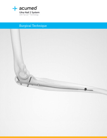
Acumed Ulna Nail 2 System Surgical TechniqueUlna Nail 2 Surgical TechniqueFigure 11Preoperative Planning and EvaluationEvaluate the location and characteristics of thefracture(s) using fluoroscopy.It may be necessary to reference the uninjured contralateralulna to estimate length.Place the patient in a supine position and use a radiolucentarm board (Figure 1). Alternatively, the patient can be placedin a lateral recumbent position, with the arm brought over thepatient's torso (Figure 2).Note: Radiographs in both the anterior to posterior and lateralplanes are recommended.Figure 2Figure 32Incision and Entry PointThe ulna fracture can be reduced and fixed using anentirely percutaneous (closed) technique. Make a 10–20 mmincision longitudinally along the tip of the olecranon to exposethe implant entry site (Figure 3). Carry the dissection downsharply through the subcutaneous tissues and split the tricepstendon longitudinally.The entry point for the nail should be centered on theolecranon process, directly in line with the proximalintramedullary canal of the ulna.Warning: Care must be taken to avoid the ulnar nerve.10
Acumed Ulna Nail 2 System Surgical TechniqueUlna Nail 2 Surgical Technique [continued]3Ulna Canal PreparationInsert the 2.0 mm x 9" ST Guide Wire (WS-2009ST)in the center of the olecranon process, directly in line withthe proximal intramedullary canal of the ulna (Figure 4).Confirm under fluoroscopy that the guide wire is centrallylocated in both posterior-to-anterior (P/A) and lateral-to-medial(L/M) planes.Figure 4Note: Avoid penetrating the cortical bone of theintramedullary canal with the guide wire to ease subsequentreaming and nail insertion.2.0 mm x 9" STGuide Wire(WS-2009ST)11
Acumed Ulna Nail 2 System Surgical TechniqueUlna Nail 2 Surgical Technique [continued]4Figure 5Nail DrillingSlide the FFN Soft-Tissue Protector (80-2896) overthe 2.0 mm x 9" ST Guide Wire (WS-2009ST) and ensure it isdown to the bone surface. Place the cannulated FFN 6.5 mmDrill (80-4039) over the guide wire (Figure 5). Drill to the lastdepth marking, indicated by the letter “U" (Figure 6 and 7)Note: The drill depth can also be confirmed under fluoroscopyby ensuring the olecranon tip is aligned with the last notch onthe drill.Note: In larger patients, the nail may need to be inserteddeeper within the metaphysis so that the proximal screwsproperly target the olecranon and coronoid processes. Toensure the proximal end of the nail still provides corticalsupport, an optional end cap can be used to extend theoverall nail length. If using the optional FFN End Cap(4014-0XXX), drill with the FFN 6.5 mm Drill through the FFNSoft-Tissue Protector to the corresponding depth marking onthe drill, labeled “U.” This will correspond to the proper FFNEnd Cap inserted in Step 9.Figure 6Figure 7Note: There is an optional Cortex Awl w/Quick Release(80-3795) that can help create an initial entry point priorto placing the 2.0 mm x 9" ST Guide Wire. The awl is notintended to be used through the FFN Soft-Tissue Protector.Depth indicators found on the awl correspond with the surfaceof the bone. If using the optional FFN End Cap (4014-0XXX),engage the bone to the corresponding depth marking on theawl, labeled “U.” This will correspond to the proper FFN EndCap inserted in Step 9.2.0 mm x 9" STGuide FN 6.5 mm Drill(80-4039)Cortex Awl w/Quick Release(80-3795)FFN End Cap(4014-0XXX)
Acumed Ulna Nail 2 System Surgical TechniqueUlna Nail 2 Surgical Technique [continued]5Canal ReamingRemove the FFN 6.5 mm Drill (80-4039) and the2.0 mm x 9" ST Guide Wire (WS-2009ST). Ensure that theFFN Soft-Tissue Protector (80-2896) remains in place andis fully seated on the bone surface. Sequentially ream theintramedullary canal through the FFN Soft-Tissue Protector,starting with the FFN 3.1 mm Reamer (80-2460), by handusing the Quick Release T-Handle (MS-T1212) or under power(Figures 8, 9, and 10). Increase in diameter until the desiredcortical engagement is achieved.Figure 8Refer to the FFN Reamer Diameter table below:FFN Reamer DiameterUlna Nail 2 DiameterFFN 3.1 mm Reamer(80-2460)3.0 mm Ulna Nail 2(4011-30XXN-S)FFN 3.7 mm Reamer(80-2461)3.6 mm Ulna Nail 2(4011-36XXN-S)FFN 4.1 mm Reamer(80-2462)4.0 mm Ulna Nail 2(4011-40XXN-S)Figure 9Note: If resistance is met during reaming, retract slightly andre-advance and oscillate to allow the blunt tip of the reamer tocenter within the center of the canal.Note: If reading under fluoroscopy, take care to ensure thereamer is centered in the canal.Figure 10FFN 6.5 mm Drill(80-4039)2.0 mm x 9" STGuide Wire(WS-2009ST)FFN SoftTissue Protector(80-2896)FFN 3.1 mmReamer(80-2460)Quick ReleaseT-Handle(MS-T1212)13
Acumed Ulna Nail 2 System Surgical TechniqueUlna Nail 2 Surgical Technique [continued]6Ulna Nail SelectionAdvance the reamer to the desired nail depth andleave the reamer and soft-tissue protector in place (Figure 11).The chosen reamer will determine the nail diameter selection.Figure 11FFN Reamer DiameterUlna Nail 2 DiameterFFN 3.1 mm Reamer(80-2460)3.0 mm Ulna Nail 2(4011-30XXN-S)FFN 3.7 mm Reamer(80-2461)3.6 mm Ulna Nail 2(4011-36XXN-S)FFN 4.1 mm Reamer(80-2462)4.0 mm Ulna Nail 2(4011-40XXN-S)With the FFN Reamer in place and the FFN Soft-TissueProtector seated on the bone, read the laser marks on theFFN Reamer as it aligns with the back end of the FFNSoft-Tissue Protector cannula to determine the proper naillength (Figure 12). Once all nail measurements have beenrecorded, remove reamer and FFN Soft-Tissue Protector.Figure 12Ulna Nail 2 DiameterUlna Nail 2 Length3.0 mm Ulna Nail 2120, 170, 190, 210, 230,250, 270 mm3.6 mm Ulna Nail 2120, 170, 190, 210, 230,250, 270 mm4.0 mm Ulna Nail 2120, 170, 190, 210, 230,250, 270 mmNote: All Ulna Nail 2 tail diameters are 6.35 mm, regardless ofthe nail shaft diameter.Warning: Choosing a nail that is too long may result inpenetration of articular joint space or leaving the nail tooproud. If between lengths, make sure to select the shorter ofthe two nails.143.0 mm UlnaNail 2(4011-30XXN-S)3.6 mm UlnaNail 2(4011-36XXN-S)4.0 mm UlnaNail 2(4011-40XXN-S)FFN 3.1 mmReamer(80-2460)FFN 3.7 mmReamer(80-2461)FFN 4.1 mmReamer(80-2462)
Acumed Ulna Nail 2 System Surgical TechniqueUlna Nail 2 Surgical Technique [continued]7Ulna Nail to Base Plate AttachmentFigure 13Place the FFN Locking Bolt (80-2452) through thebarrel mount on the FFN Base Plate (80-2448) (Figure 13).Line the nail up with the alignment tab and use the FFNLocking Bolt to secure the ulna nail to the FFN Base Plate.Securely tighten the bolt by using the FFN T15 HexalobeDriver (80-3619) or any of the slots in the FFN Handle(80-3885).Figure 14Note: The bow of the nail should angle away from themarkings and the assembly posts on the base plate.Optional: To attach the optional FFN Handle, insert the FFNBolt (80-3886) into the FFN Handle and rotate clockwise untilseated (Figure 15). Thread the combined FFN Bolt and FFNHandle into either of the threaded holes in the FFN Base Plate(Figure 14). The FFN Bolt has a retaining feature that preventsthe bolt from falling out of the FFN Handle.8Targeting Guide AssemblyFigure 15Attach the FFN Primary Targeting Guide (80-2454)to the FFN Base Plate (80-2448) by sliding the two posts onthe FFN Base Plate into the hole and slot of the FFN PrimaryTargeting Guide.Insert the FFN Locking Knob (80-2499) through the proximalcenter hole of the FFN Primary Targeting Guide. Rotate theknob clockwise to tighten the FFN Primary Targeting Guide tothe FFN Base Plate (Figure 16).Note: The posts of the FFN Base Plate only allow for oneassembly orientation and are not side-specific.Note: The FFN Primary Targeting Guide sits posterior tothe ulna. The targeting assembly may be rotated slightlywhen placing screws to target the olecranon and/orcoronoid processes.Figure 16FFN Locking Bolt(80-2452)FFN Base Plate(80-2448)FFN T15 HexalobeDriver(80-3619)FFN Handle(80-3885)FFN Bolt(80-3886)FFN PrimaryTargeting Guide(80-2454)FFN Locking Knob(80-2499)15
Acumed Ulna Nail 2 System Surgical TechniqueUlna Nail 2 Surgical Technique [continued]9Nail Insertion and PositioningEnsure the fracture is reduced and insert the selectedulna nail into the reamed bone so the tip of the nail is alignedwith the tip of the olecranon (Figures 17 and 21). Insert the FFN3.5 mm Cannula (80-2476) into the angled targeting hole onthe targeting guide, labeled “Ulna” (Figure 18).Figure 17A lateral fluoroscopic view should be obtained to verifythat the trajectory of the most proximal screw will target thetip of the olecranon process and that the proximal end ofthe nail has been inserted below the surface of the bone.Glide the nail tip past the fracture site and down to thedistal metaphysis. The ulna nail should pass easily downthe canal without impaction. If resistance is met, the nailshould be withdrawn, and the canal checked again with theappropriate reamer.The FFN Handle (80-3885) may be used to internally orexternally rotate to ensure alignment. The handle may also beremoved if desired.Figure 18Figure 19Insert the 2.0 mm x 9" ST Guide Wires (WS-2009ST) throughthe targeting guide for additional stability; however they willneed to be removed when retracting the ulna nail for optionalTip-Loc insertion in step 9C (Figure 19). The center-mostproximal K-wire hole identifies the junction of the ulna nail andthe FFN Base Plate (80-2448) (Figure 20).Note: If using an optional FFN End Cap (4014-0XXX), locatethe notches on the barrel section of the FFN Base Plate.These notches are viewable under fluoroscopy or directvisualization and indicate the approximate FFN End Caplength. Insert the nail to the desired depth and confirm theend cap length from the 0.4 mm, 5 mm, 10 mm, or 15 mm.Optional FFN End CapsFigure 20FFN 0.4 mm End Cap (4014-0600)FFN 5 mm End Cap (4014-0705)FFN 10 mm End Cap (4014-0710)FFN 15 mm End Cap (4014-0715)Warning: Ensure that the screws will avoid the joint space.Note: To use the optional Tip-Loc to lock the tip of the nail,allowing two points of fixation, continue to Step 9A. If not,proceed to Step 10.Figure 21FFN 3.5 mmCannula(80-2476)16FFN Handle(80-3885)2.0 mm x 9" STGuide Wire(WS-2009ST)FFN Base Plate(80-2448)FFN End Cap(4014-0XXX)
Acumed Ulna Nail 2 System Surgical TechniqueUlna Nail 2 Surgical Technique [continued]9AOptional Tip-Loc Incision andClamp PlacementFigure 22With the ulna nail inserted to the correct depth, identify thenail tip, which narrows to 2.6 mm in diameter in the last 1.5" ofthe nail, under fluoroscopy and mark the center of that regionon the skin. Use this mark as the center point for a 2–3 cmincision along the medial ulna (Figure 22). Bluntly dissectaround the ulna to make room for the clamp arms.Assemble the Tip-Loc Rotary Cannula (80-3760) into thecentral hole of the Tip-Loc Clamp (80-3891) by aligning theinsert/remove arrows with the arrow on the clamp. Once thecannula is engaged into the clamp, rotate it 180 in eitherdirection until the arrow aligns with the 0 mm line(Figures 23 and 24).Place the radiolucent clamp arms through the incision aroundthe bone with the clamp handles pointing distally (Figure 26).Figure 23Note: It is recommended to place at least one of the twoprovided 2.0 mm Short Guide Wires (35-0023) through eitherK-wire hole near the clamp cannula into the bone to provideadditional stability to the clamp.Note: Care should be taken to ensure that the rotatingcannula sits perpendicular to the long axis of the bone andflush on the bone.Note: The 120 mm length ulna nail in all three diameters doesnot accept the Tip-Loc Bushing & Set Screw as these shortnails were designed for more proximal ulna fractures in whichdistal locking is not necessary.Figure 24Figure 25Tip-Loc RotaryCannula(80-3760)Tip-Loc Clamp(80-3891)Figure 262.0 mm ShortGuide Wire(35-0023)17
Acumed Ulna Nail 2 System Surgical TechniqueUlna Nail 2 Surgical Technique [continued]9BFigure 27Optional Tip-Loc Ulna NailTargetingUnder fluoroscopy, use the circle-circle technique to align thetwo radiopaque rings on the proximal and distal end of therotating cannula within the Tip-Loc Clamp (80-3891) to providevisualization down the cannula (Figures 27 and 28).If the tip of the ulna nail is not positioned in the center of thecannula, rotate the cannula in 1 mm increments until the tip ofthe nail is clearly centrally located within the two circles. Figure 28 Clockwise Rotation Shifts cannula rightCounterclockwise Rotation Shifts cannula left9COptional Tip-Loc Drilling &PreparationOnce the tip of the ulna nail is targeted through the cannulawithin the Tip-Loc Clamp (80-3891), retract the ulna nail forsubsequent drilling until the tip of the ulna nail is no longervisible through the cannula (Figure 29).To drill for the body of the Tip-Loc Bushing (3017-650XX),insert the FFN Near Cortex Drill (80-3696) through thecannula within the Tip-Loc Clamp and drill under power untilit bottoms out with the back of the cannula (Figure 30).Remove the FFN Near Cortex Drill and insert the FFN FarCortex Drill (80-3697) through the cannula within the TipLoc Clamp. Drill the 2 mm trocar tip through the far cortexand ream the inside region of the far cortex with the FFN FarCortex Drill (Figure 31).Figure 29Figure 30The proper Tip-Loc Bushing length is determined when theFFN Far Cortex Drill laser marks are flush against the back ofthe cannula within the Tip-Loc Clamp (Figure 32). The Tip-LocBushings are available in lengths ranging from 6 mm–16 mm,with 1 mm increments.The correct bushing length can also be identified underfluoroscopy by identifying where the notches on the FarCortex Drill are in relation to the near cortex. The notchesare 2 mm apart and correspond to the associated Tip-LocBushing sizes. The most distal notch, closest to the drill tip,corresponds to the 6 mm Tip-Loc Bushing size, and so on.Tip-Loc Clamp(80-3891)18Tip-Loc Bushing(3017-650XX)FFN Near CortexDrill(80-3696)FFN Far CortexDrill(80-3697)
Acumed Ulna Nail 2 System Surgical TechniqueUlna Nail 2 Surgical Technique [continued]Tip-Loc Bushing & Set Screw KitPartnumberTip-Loc Bushing & Set Screw, 6 mm47-0006-STip-Loc Bushing & Set Screw, 7 mm47-0007-STip-Loc Bushing & Set Screw, 8 mm47-0008-STip-Loc Bushing & Set Screw, 9 mm47-0009-STip-Loc Bushing & Set Screw, 10 mm47-0010-STip-Loc Bushing & Set Screw, 11 mm47-0011-STip-Loc Bushing & Set Screw, 12 mm47-0012-STip-Loc Bushing & Set Screw, 13 mm47-0013-STip-Loc Bushing & Set Screw, 14 mm47-0014-STip-Loc Bushing & Set Screw, 15 mm47-0015-STip-Loc Bushing & Set Screw, 16 mm47-0016-SFigure 31Note: The FFN Far Cortex Drill (80-3697) has a trocar tipdesigned to drill through the far cortex, but the transition tothe bigger diameter is designed to be blunt without sharpcutting features. This will provide a hard stop when it reachesthe far cortex, indicating that the surgeon has drilled farenough and allowing some reaming to prepare the insidecanal for the bushing.Figure 32Caution: Take care not to penetrate the far cortex with theFFN Far Cortex Drill.Note: If needed, a Cortex Awl w/Quick Release (80-3795)can be attached to the Quick Release T-Handle (MS-T1212)and inserted by hand through the cannula within the Tip-LocClamp (80-3891) to further clear the site for the bushing.Note: If the Tip-Loc Bushing measurement is between the2 mm sizing increments, select the larger of the two sizes.The intention of the Tip-Loc Bushing is to achieve bicorticalfixation within the ulna.Tip-Loc Bushing &Set Screw Kit,(47-00XX-S)FFN Far CortexDrill(80-3697)Cortex Awl w/Quick Release(80-3795)Quick ReleaseT-Handle(MS-T1212)Tip-Loc Clamp(80-3891)19
Acumed Ulna Nail 2 System Surgical TechniqueUlna Nail 2 Surgical Technique [continued]9DFigure 33Optional Tip-Loc BushingInsertionTo attach the selected Tip-Loc Bushing (3017-65XXX-S),place the Tip-Loc Coupler Attachment (80-2484) throughthe Tip-Loc Bushing Coupler Handle (80-2483) (Figure 33).Thread the selected length Tip-Loc Bushing onto the end ofthe threaded Tip-Loc Bushing Coupler Handle and ensure thatthe bushing recess notches engage with the notches in theTip-Loc Coupler Attachment.Figure 34Place the Tip-Loc Bushing Coupler Driver and attachedbushing through the cannula within the Tip-Loc Clamp(Figure 34). Thread the Tip-Loc Bushing into the bone until themarking on the Tip-Loc Coupler shaft is flush with the back ofthe cannula within the Tip-Loc Clamp (Figure 35). Dependingon bone quality, the surgeon may feel a semi-solid end stopwhen the bushing reaches the far cortex.Align the Tip-Loc Bushing Coupler Handle so that theflat surfaces are parallel with the ulna nail. This will orientthe opening of the Tip-Loc Bushing towards the tip of theulna nail.Readvance the ulna nail to the correct depth and through theTip-Loc Bushing. Rotate the Tip-Loc Bushing Coupler Handlein either direction to help the bushing properly accept the nailtip (Figure 36).Figure 35Note: There is a small offset "kick" in the most distal 9.5 mmof the ulna nail to assist in targeting and advancing the nailtip through the bushing. If the nail tip is not easily advancingthrough the bushing, the ulna nail and FFN Base Plate(80-2448) can be rotated to take advantage of the kick toalign the very tip of the nail with the bushing opening.Note: If the ulna nail fails to advance through the bushingopening, the nail tip kick can be manually increased duringsurgery to create a bigger offset.Disengage the Tip-Loc Coupler Attachment from the Tip-LocBushing by rotating it counter-clockwise, but leave the couplerhandle in place to aid in set screw insertion.Figure 36Tip-Loc Bushing(3017-650XX)20Tip-Loc CouplerAttachment(80-2484)Tip-Loc BushingCoupler Handle(80-2483)FFN Base Plate(80-2448)
Acumed Ulna Nail 2 System Surgical TechniqueUlna Nail 2 Surgical Technique [continued]Note: It is recommended to assess the successfulinsertion of the ulna nail through the bushing by takingan oblique view fluoroscopic image and also rotating thecoupler handle. The nail has not advanced through theTip-Loc Bushing (3017-650XX) if the handle can rotate morethan 45 degrees (Figures 37 and 38). In this case retract thenail and use the technique described above to advance thenail through the bushing opening.Figure 37Note: It is recommended to insert the remaining 3.5 mmNonlocking Hexalobe Screws (30-02XX) and 3.5 mmHeadless Hexalobe Screws (3018-470XX) PRIOR to placingthe Tip-Loc Set Screw (3017-250XX) in Step 10D to ensureall screw trajectories are correct and adjustments have beenmade for rotation and length. However, the surgeon maychoose to lock the tip at this point to allow for compression ofthe fracture site by pulling on the nail attachment. To lock thetip with the set screw, proceed to Step 10D. Ensure that bonealignment and screw trajectories are correct before lockingthe bushing and set screw.Figure 383.5 mm NonlockingHexalobe Screws(30-02XX)3.5 mm HeadlessHexalobe Screws(3018-470XX)Tip-Loc Bushing(3017-650XX)Tip-Loc Set Screw(3017-250XX)21
Acumed Ulna Nail 2 System Surgical TechniqueUlna Nail Surgical Technique [continued]10Posterior / Anterior ScrewPlacementIt is recommended to place at least one P/A screw. Place themost proximal screw first to ensure correct placement withinthe olecranon process, followed by one of the two options ofthe coronoid process screws. Be sure to check for sufficientbone purchase and no joint space obstruction.Figure 39Place the FFN 3.5 mm Cannula (80-2476) through the angledhole of the FFN Primary Targeting Guide (8
Designed in conjunction with Roy Sanders, MD, the Acumed Ulna Nail 2 includes three nail diameters and seven length options, power reamers and carbon fiber radiolucent targeting guides to streamline the procedure,