Transcription
SOIL NAIL WALL BASICSJohn G. Delphia, P.E.TxDOT Bridge DivisionGeotechnical Branch
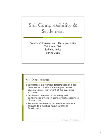
Soil Nail BasicsSoil Nail Walls Technique to reinforce andstrengthen the soil Construction proceeds fromthe top down Nails (grouted steel bars)are passive reinforcement Nails limit thedisplacement of the soilFrom:2
Soil Nail BasicsSoil Nail WallsDesignLayout SheetsDetail SheetsSpecificationConstructionInspection- follow thedetails- Adhere to thespecifications3
Soil Nail Basics Soil Nail Walls Need to BeDesigned for the site conditions There Are Not Any Standards Not a Proprietary System. Complete details must beprovided.4
Soil Nail BasicsWall Layout Soil borings throughzone to be nailed Provide separationfrom bridge abutmentwhere possible Limit base-of-wallembedment Consider futureexcavation at base ofwall.5
Soil Nail BasicsSOIL NAIL DESIGNDesign Tools FHWA Design Manual – Soil Nail Walls ReferenceManual (GEC 7)Various Computer Programs are available:- GoldNail Computer Program- SnailZ Computer Program- SNAP-2 Computer Program6
Soil Nail BasicsSoil Parameters Determine drained soil parametersfrom laboratory testing (difficult),correlation with PI, or experience. Drained Cohesion should be very low(0 - 100 psf) Drained Angle of Friction (φ’) isnormally between 24 and 34degrees Drained soil parameters determinewhat portion of load is transferred tothe nails from the face.7
Soil Nail BasicsSoil Parameters Ultimate Pullout Resistanceis the anticipated ultimateshear resistance per foot ofnail Use Texas ConePenetrometer (TCP) tests todetermine the UltimatePullout Resistance Same method ascalculating skin friction ona drilled shaft or pile8
Soil Nail BasicsNail Spacing Guidelines Nail Spacing impacts the loading on the soil nailsFor clay soils use a tighter spacingTop of WallTop Nailwithin 2.5’of Top ofWallVertical Spacing3.0’ – 4.0’Bottom of WallBottom Nailwithin 3.0’of Bottomof WallHorizontal Spacing 3.0’ – 4.5’9
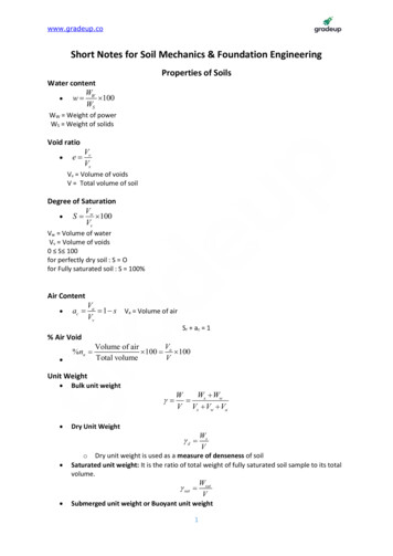
Soil Nail BasicsHead Strength Head Strength is defined as the capacityof the nail anchorage in the fascia High Head Strength shortens the nailsand allows the lowest nails to carry adisproportionate amount of load Do not allow lowest anchors to carry thehighest loads From:To Head StrengthIf required, adjust the head strength untilthe upper half of wall is carrying at leasthalf of the total load10
Soil Nail BasicsFull-scale wall tests show that the uppernails carry the highest loadsTxDOTMonitoredSoil NailWallFrom:Nail loads may increase over time in thewall ( high PI clay soils )11
Soil Nail BasicsSOIL NAIL SPECIFICATIONSpecification is an updated version of the Statewide SpecialSpecification 4116 and includes materials, equipment, construction,testing, measurement, and payment.12
Soil Nail BasicsDesignLayout SheetsDetail SheetsSOIL NAILED WALLS NEEDTO BE DESIGNED FOR THESITE CONDITIONS PRESENTTHERE ARE NOT ANY STANDARD DETAIL SHEETS FOR THEMEACH WALL NEEDS TO BE TREATED INDIVIDUALLY13
Soil Nail BasicsSOIL NAIL LAYOUTSIdentify the following: top and bottom of wall nail locations elevations of rows of nails non-typical nail spacing obstructions14
Soil Nail BasicsSOIL NAIL LAYOUTSSometimes soil nails may need to beangled.The angle needs to be identified on thelayout.From:15
Soil Nail BasicsSOIL NAIL LAYOUTS94 nails @ 22’ length 2068’21 nails @ 18’length 378’16 nails @ 12’length 192’16
Soil Nail BasicsSOIL NAIL LAYOUTS94 nails @ 22’ length 2068’21 nails @ 18’length 378’16 nails @ 12’length 192’17
Soil Nail BasicsSOIL NAIL LAYOUTS94 nails @ 22’ length 2068’21 nails @ 18’length 378’16 nails @ 12’length 192’18
Soil Nail BasicsSOIL NAIL TESTSTWO TYPES OF TESTS1. Verification Tests- these are performed prior to construction- on sacrificial soil nail anchors- tests both the strength of the soil and theContractor’s methods of installation2. Proof Tests- these are performed on production soil nail anchors- performed to a lower load than verification nails- tests the Contractor’s methods of installation19
Soil Nail BasicsSOIL NAIL DETAIL SHEET20
Soil Nail BasicsSOIL NAIL DETAIL SHEET21
Soil Nail BasicsSOIL NAIL DETAIL SHEET22
Soil Nail BasicsSOIL NAIL DETAIL SHEET23
Soil Nail BasicsSOIL NAIL DETAIL SHEETWeephole DetailDRAINAGE DETAILS24
Soil Nail BasicsSOIL NAIL DETAIL SHEETMake sureto updatethe GeneralNotes to beconsistentwith Item410 “SoilNailAnchors”25
Soil Nail BasicsSOIL NAIL DETAIL SHEETCONSTRUCTION PROCEDURE:The slope in front of the retaining wall shall be removed inlifts. The depth of each lift shall be limited to the amountnecessary to install a single horizontal row of Soil Nails. At notime shall more than 4’-0” of un nailed vertical cut be exposed. Thelength of each lift removed shall be limited to the amount that canbe nailed in one day. At no time shall any un-nailed cut face beexposed for over 24 hours.Upon completion of each day's installation of nails, pneumaticallyplaced concrete shall be applied to the cut face. The concrete shallbe reinforced with a single layer of Welded Wire Reinforcing Fabric,4" X 4" - W2.9. and #4 waler bars as shown. Anchor Plate, beveledwasher, and nuts shall be tightened up to the face of the PPC.When all rows of nails have been placed, the permanent ConcreteFascia Wall shall be installed The permanent concrete fascia wallshall be completed within 30 working days of the completion of nailplacement.The items inRED need tomatch the soilconditions andjob26
Soil Nail BasicsWHAT TYPES OF FACING OPTIONS ARE AVAILABLE?Cast in-placePrecast PanelsSculptedShotcrete27
Soil Nail BasicsSOIL NAIL WALLS DEPEND UPON A PROPER DESIGN ANDDETAILS DEVELOPED FOR THE SITE SPECIFIC SOIL CONDITIONSAND GEOMETRY28
Soil Nail BasicsQUESTIONS?29
Soil Nail BasicsCopyright 2015 Texas Department of Transportation All Rights ReservedEntities or individuals that copy and present state agency information must identify the source of the content,including the date the content was copied. Entities or individuals that copy and present state agency informationon their websites must accompany that information with a statement that neither the entity or individual nor theinformation, as it is presented on its website, is endorsed by the State of Texas or any state agency. To protect theintellectual property of state agencies, copied information must reflect the copyright, trademark, service mark,or other intellectual property rights of the state agency whose protected information is being used by the entity orindividual. Entities or individuals may not copy, reproduce, distribute, publish, or transmit, in any way this contentfor commercial purposes. This presentation is distributed without profit and is being made available solelyfor educational purposes. The use of any copyrighted material included in this presentation is intended tobe a “fair use” of such material as provided for in Title 17 U.S.C. Section 107 of the U.S. Copyright Law.30
Head Strength Head Strength is defined as the capacity of the nail anchorage in the fascia High Head Strength shortens the nails and allows the lowest nails to carry a disproportionate amount of load Do not allow lowest anchors to carry the highest loads If required, adjust the head s