Transcription
Experiment #3: Parallel Plate CapacitorStudent: Keith GurrCourse: PHYS 2426LDate: October 1, 2014Partner: Waylon HowseGeneral note: This lab report is 15 pages long. This is by no means what is expected.Most lab reports are several pages long, but nothing thing involved. This is just anexample of a student who went above & beyond.
In-depth review of the theory thatis related to the experiment. Thisincludes descriptions of the physics,the equipment, definitions, equations, etc.Statement of the objective of the laboratory experimentIntroductionThis report serves to investigate and analyze, through scientific experimentation, therelationship between both potential difference and capacitance with the plate separation distanceIn-depth review of a fixed charge parallel plate capacitor.A capacitor (originally known as a condenser) is a passive two-terminal electricalof the theory thatis related to the component used to store energy electrostatically in an electric field. The forms of practicallab experiment. capacitors vary widely, but all contain at least two electrical conductors (plates) separated by aThis includesdielectric (i.e. insulator). The conductors can be thin films, foils or sintered beads of metal ordescriptions ofthe physics, the conductive electrolyte, etc. The non-conducting dielectric acts to increase the capacitor's chargecapacity. A dielectric can be glass, ceramic, plastic film, air, vacuum, paper, mica, oxide layerequipment,etc. Capacitors are widely used as parts of electrical circuits in many common electrical devices.definitions,equations, etc. Unlike a resistor, an ideal capacitor does not dissipate energy. Instead, a capacitor stores energyin the form of an electrostatic field between its plates.When there is a potential difference across the conductors (e.g., when a capacitor isattached across a battery), an electric field develops across the dielectric, causing positive charge Q to collect on one plate and negative charge Q to collect on the other plate. If a battery hasbeen attached to a capacitor for a sufficient amount of time, no current can flow through thecapacitor. However, if a time-varying voltage is applied across the leads of the capacitor, adisplacement current can flow.An ideal capacitor is characterized by a single constant value for its capacitance.Capacitance is expressed as the ratio of the electric charge Q on each conductor to the potentialdifference V between them. The SI unit of capacitance is the farad (F), which is equal to onecoulomb per volt (1 C/V). Typical capacitance values range from about 1 pF (10 12 F) to about1 mF (10 3 F).The capacitance is greater when there is a narrower separation between conductors andwhen the conductors have a larger surface area. In practice, the dielectric between the platespasses a small amount of leakage current and also has an electric field strength limit, known asthe breakdown voltage. The conductors and leads introduce an undesired inductance andresistance.Capacitors are widely used in electronic circuits for blocking direct current whileallowing alternating current to pass. In analog filter networks, they smooth the output of powersupplies. In resonant circuits they tune radios to particular frequencies. In electric powertransmission systems, they stabilize voltage and power flow.The simplest capacitor consists of two parallel conductive plates separated by a dielectric(such as air) with permittivity ε. The model may also be used to make qualitative predictions forother device geometries. The plates are considered to extend uniformly over an area A and acharge density ρ Q/A exists on their surface. Assuming that the width of the plates is muchgreater than their separation d, the electric field near the center of the device will be uniform withthe magnitude E ρ/ε. The voltage is defined as the line integral of the electric field between theplatesEquations clear andon their own linesSolving this for C Q/V reveals that capacitance increases with area of the plates, anddecreases as separation between plates increases.
The capacitance is therefore greatest in devices made from materials with a highpermittivity, large plate area, and small distance between plates.A parallel plate capacitor can only store a finite amount of energy before dielectricbreakdown occurs. The capacitor's dielectric material has a dielectric strength Ud which sets thecapacitor's breakdown voltage at V Vbd Udd. The maximum energy that the capacitor can storeis thereforeWe see that the maximum energy is a function of dielectric volume, permittivity, anddielectric strength per distance. So increasing the plate area while decreasing the separationbetween the plates while maintaining the same volume has no change on the amount of energythe capacitor can store. Care must be taken when increasing the plate separation so that the aboveassumption of the distance between plates being much smaller than the area of the plates is stillvalid for these equations to be accurate. In addition, these equations assume that the electric fieldis entirely concentrated in the dielectric between the plates. In reality there are fringing fieldsoutside the dielectric, for example between the sides of the capacitor plates, which will increasethe effective capacitance of the capacitor. This could be seen as a form of parasitic capacitance.For some simple capacitor geometries this additional capacitance term can be calculatedanalytically. It becomes negligibly small when the ratio of plate area to separation is large.Most types of capacitor include a dielectric spacer, which increases their capacitance.These dielectrics are most often insulators. However, low capacitance devices are available witha vacuum between their plates, which allows extremely high voltage operation and low losses.Variable capacitors with their plates open to the atmosphere were commonly used in radio tuningcircuits. Later designs use polymer foil dielectric between the moving and stationary plates, withno significant air space between them.In order to maximize the charge that a capacitor can hold the dielectric material needs tohave as high a permittivity as possible, while also having as high a breakdown voltage aspossible.Several solid dielectrics are available, including paper, plastic, glass, mica and ceramicmaterials. Paper was used extensively in older devices and offers relatively high voltageperformance. However, it is susceptible to water absorption, and has been largely replaced byplastic film capacitors. Plastics offer better stability and ageing performance, which makes themuseful in timer circuits, although they may be limited to low operating temperatures andfrequencies. Ceramic capacitors are generally small, cheap and useful for high frequencyapplications, although their capacitance varies strongly with voltage and they age poorly. Glassand mica capacitors are extremely reliable, stable and tolerant to high temperatures and voltages,but are too expensive for most mainstream applications. Electrolytic capacitors and supercapacitors are used to store small and larger amounts of energy, respectively, ceramic capacitorsare often used in resonators, and parasitic capacitance occurs in circuits wherever the simpleconductor-insulator-conductor structure is formed unintentionally by the configuration of thecircuit layout.!
Materials and MethodsNote that this section is no longer a requirement. If you follow the lab manualEXACTLY without deviation, you may simply write something along the linesof “see lab manual for equipment and procedure.”This experiment required the use of a basic variable capacitor, a DC power supply (0-8VDC 0-5 A), a basic electrometer, a low capacitance test cable, two banana cables, and onealligator clip.The first portion of this experiment involved measuring and recording the radius of theplates of the capacitor. This recorded value was used to calculate of the plate surfaces of thecapacitor. The next step was to connect the low capacitance test cable to the basic electrometerusing the BNC connection. This required the ground lead of the test cable to be connected to themovable plate and the other lead to be connected to the fixed plate of the capacitor. The next stepwas to use the two banana cables to connect the ground of the DC power supply to theelectrometer and the positive terminal to the alligator clip. The alligator clip was then connectedto the fixed plate of the capacitor. The next step was to turn on the DC power supply and adjustthe voltage reading until a reading of 30 V was displayed on the electrometer. The positivealligator clip lead was then removed from the fixed plate of the capacitor. The final step of thisportion of the experiment was to the set the plate separation of the capacitor to 10 cm. Thisdistance value along with corresponding potential difference value was then recorded on the datasheet.The second portion of this experiment involved repeating all the steps performed in thefirst portion using gradually decreased plate separation distances. For plate separation distancesgreater than 5 cm, the separation distance was lowered in 1 cm increments. For plate separationdistances less than 5 cm, the separation distance was lowered in 0.5 cm increments. Each ofthese decreased plate separation distances and the corresponding measured potential differencevalue was recorded on the data sheet. As a final step in this portion of the experiment, theamount of capacitance for each of the recorded separation distances including the initial 10 cmwas calculated and recorded on the data sheet.The third portion of this experiment began by conducting a second trial of the entireexperiment. This involved repeating all the steps performed in the first and second portions andrecording all the relevant results obtained on the data sheet. Once this was completed, the DCpower supply was turned off and the entire equipment set up was dismantled to pre-experimentconfiguration.The final portion of this experiment involved using the spreadsheet program Excel togenerate two graphical plots of the recorded data. The first of these plots graphically comparedthe potential difference values to the corresponding plate separation values while the second ofthese plots graphically compared the calculated capacitance values to the corresponding plateseparation values. Both of the two plots contained the data obtained from the first and secondtrials of the experiment. A line of best fit was also incorporated into each plot and for each of thetwo trials.
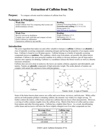
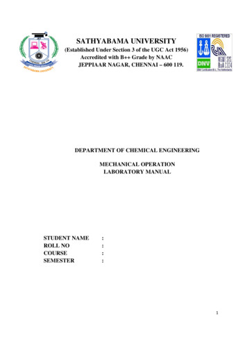
Tables are often introduced with a few sentences.ResultsTable 1 contains the recorded measurement of the radius of the parallel plates of the basicvariable capacitor for Trial 1. It also contains the calculated measurement for the area of thesame parallel plates. The formula used to calculate the area is as follows:A πr2Using the above formula, the value for the area of the parallel plates was calculated asfollows:r 8.90 x 10⁻² mr 8.90 cmA (π) (8.90 x 10⁻² m)2A (π) (7.92 x 10⁻³ m2)A 2.49 x 10⁻² m2A 2.49 x 102 cm2Parallel PlatesTable 1 – Trial 1Radius (cm)8.90 cmArea (cm2)2.49 x 102 cm2Table 1: Radius and Area of the Parallel Plates of the Capacitor for Trial 1table footnotes are sometimesuseful, but not necessaryTable 2 contains the recorded separation distances in meters and corresponding recordedpotential difference (voltage) values in volts for Trial 1 of this experiment. It also contains thecorresponding calculated capacitance values in farads for Trial 1 of the experiment. The formulaused to calculate the capacitance is as follows:C (ε0)(A/d)Using the above formula, the value for the capacitance for each of the measured plateseparation distances was calculated as follows:ε0 8.854 x 10⁻¹² F/mA 2.49 x 10⁻² m2d plate separation distanceC (8.854 x 10⁻¹² F/m) ((2.49 x 10⁻² m2) / (1.00 x 10⁻² m))C (8.854 x 10⁻¹² F/m) (2.49 m)C 2.20 x 10⁻¹¹ FC 2.20 x 10⁻⁵ µFSample calculations are required.Show at least one sample calculationfor every formula used. Show all steps.
C (8.854 x 10⁻¹² F/m) ((2.49 x 10⁻² m2) / (0.90 x 10⁻² m))C (8.854 x 10⁻¹² F/m) (2.76 m)C 2.44 x 10⁻¹¹ FC 2.44 x 10⁻⁵ µFC (8.854 x 10⁻¹² F/m) ((2.49 x 10⁻² m2) / (0.80 x 10⁻² m))C (8.854 x 10⁻¹² F/m) (3.11 m)C 2.75 x 10⁻¹¹ FC 2.75 x 10⁻⁵ µFC (8.854 x 10⁻¹² F/m) ((2.49 x 10⁻² m2) / (0.70 x 10⁻² m))C (8.854 x 10⁻¹² F/m) (3.55 m)C 3.14 x 10⁻¹¹ FC 3.14x 10⁻⁵ µFC (8.854 x 10⁻¹² F/m) ((2.49 x 10⁻² m2) / (0.60 x 10⁻² m))C (8.854 x 10⁻¹² F/m) (4.14 m)C 3.67 x 10⁻¹¹ FC 3.67 x 10⁻⁵ µFC (8.854 x 10⁻¹² F/m) ((2.49 x 10⁻² m2) / (0.50 x 10⁻² m))C (8.854 x 10⁻¹² F/m) (4.97 m)C 4.40 x 10⁻¹¹ FC 4.40 x 10⁻⁵ µFC (8.854 x 10⁻¹² F/m) ((2.49 x 10⁻² m2) / (0.45 x 10⁻² m))C (8.854 x 10⁻¹² F/m) (5.52 m)C 4.89 x 10⁻¹¹ FC 4.89 x 10⁻⁵ µFC (8.854 x 10⁻¹² F/m) ((2.49 x 10⁻² m2) / (0.40 x 10⁻² m))C (8.854 x 10⁻¹² F/m) (6.21 m)C 5.50 x 10⁻¹¹ FC 5.50 x 10⁻⁵ µFC (8.854 x 10⁻¹² F/m) ((2.49 x 10⁻² m2) / (0.35 x 10⁻² m))C (8.854 x 10⁻¹² F/m) (7.10 m)C 6.29 x 10⁻¹¹ FC 6.29 x 10⁻⁵ µFC (8.854 x 10⁻¹² F/m) ((2.49 x 10⁻² m2) / (0.30 x 10⁻² m))C (8.854 x 10⁻¹² F/m) (8.28 m)C 7.33 x 10⁻¹¹ FC 7.33 x 10⁻⁵ µF* NOTE: this student does EVERY calculation.This is borderline crazy and is not required.However, it may be useful to have everythingdone in one place!
C (8.854 x 10⁻¹² F/m) ((2.49 x 10⁻² m2) / (0.25 x 10⁻² m))C (8.854 x 10⁻¹² F/m) (9.94 m)C 8.80 x 10⁻¹¹ FC 8.80 x 10⁻⁵ µFC (8.854 x 10⁻¹² F/m) ((2.49 x 10⁻² m2) / (0.20 x 10⁻² m))C (8.854 x 10⁻¹² F/m) (12.43 m)C 11.00 x 10⁻¹¹ FC 11.00 x 10⁻⁵ µFC (8.854 x 10⁻¹² F/m) ((2.49 x 10⁻² m2) / (0.15 x 10⁻² m))C (8.854 x 10⁻¹² F/m) (16.57 m)C 14.67 x 10⁻¹¹ FC 14.67 x 10⁻⁵ µFC (8.854 x 10⁻¹² F/m) ((2.49 x 10⁻² m2) / (0.10 x 10⁻² m))C (8.854 x 10⁻¹² F/m) (24.85 m)C 22.00 x 10⁻¹¹ FC 22.00 x 10⁻⁵ µFTables are very neat. Each table has a title.C
General note: This lab report is 15 pages long. This is by no means what is expected. Most lab reports are several pages long, but nothing thing involved. This is just an example of a student who went above & beyond. Introduction This report serves to investigate and analyze, through scientific experimentation, the relationship between both potential difference and capacitance with the plate .