Transcription
1MECH 344/XMachine Element DesignTime: M 14:45 - 17:30Lecture 1
Contents of today's lecture IntroductionMachine DesignDesign ProcessSafety Factors
Fundamentals of MachineComponent DesignSixth EditionRobert C. Juvinall Kurt M. MarshekChapter 1Mechanical Engineering Designin Broad Perspective
4Engineering design is the process of applying the varioustechniques and scientific principles for the purpose of defining adevice, a process, or a system in sufficient detail to permit itsrealization.A Machine is:(1) An apparatus consisting of interrelated units, or(2) A device that modifies force or motionA Structure has no moving parts, e.g. bridges, buildings.
A machine is a device thattransforms energy Has fixed and moving parts Connects the source of power andthe work to be done In case of motor and generatorelectricity is converted to mechanicalmovement and vice versa In IC engine, connecting rod andcrank shaft transfers energy
The design process Design involves constrained creation Constraints: Technology limits Human and environment concerns Durability and reliability Cost Market requirements Etc.
Thedesign process REPRESENTATIONBasic requirements to be able toPERCEPTIONperform a designKNOWLEDGEAll the above interacts in yourjudgment even if you are notINTUITIONaware of itCONCEPTYou have to train your judgmentPURE CONCEPTto be able to perform solutionEMPIRICAL CONCEPT solving based thinkingNOTION IDEA
The design process A design is created after analysis, fullunderstanding of requirements andconstraints and synthesis Two individuals may not come with thesame solution to the same problem Example: Connect two straight pipes ND 4” toavoid leaking of the gas and to permit easymaintenance of the segment
Solutions to the problem Multiple: flanges, clips, clamps, seals, etc.
1. Problem Defn.2. Concept andideasThe design process3. Solutions4. Models/Prototype5. Production andworking drawingsConcurrent engineeringapproach
The design process
A Component !
18
19
20
21
22
23
24
25
26Factor of Safety N Material StrengthDesign Load
Fundamentals of MachineComponent DesignSixth EditionRobert C. Juvinall Kurt M. MarshekChapter 2Load Analysis
28
36
of Gear C 2.25” of Gear B 3.75”38
39
40
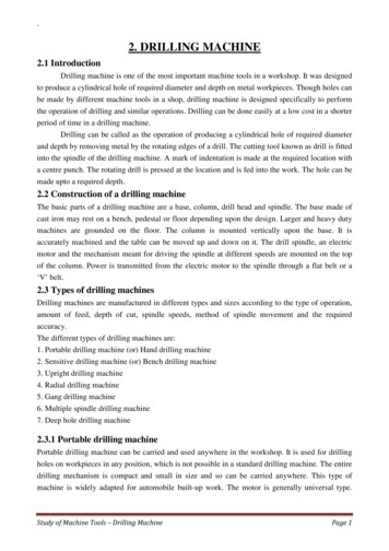
The sections chosen for load determination in the previous examples were, by simpleinspection, clearly those subjected to the most critical loading.In more complicated cases, however, several sections may be critical, and their locationsless obvious.In such instances it is often helpful to employ an orderly procedureof following the “lines of force” (approximate paths taken by the force, determinedby simple inspection) through the various parts, and noting along the way any sectionssuspected of being critical. Such a procedure is illustrated in the following example.41
Assumptions:1. The weight of the yoke connection can be ignored.2. The load is divided equally between the two prongs of the fork (the loads andyoke connection are perfectly symmetrical).3. The load in each prong is divided equally between the portions on each side ofthe hole.4. Distributed loads are represented as concentrated loads.5. The effects of pin, blade, and fork deflections on load distribution are negligible.6. The pin fits snugly in the fork and blade.42
43
44
45
Fundamentals of Machine Component Design Sixth Edition . Solutions 4. Models/Prototype 5. Production and working drawings. The design process. . Design Load 26. Chapter 2 Load Analysis Fundamentals of Machine Component Design Sixth Edition