Transcription
Application GuideGeothermal Heat PumpDesign Manual 2002 McQuay InternationalAG 31-008
Table of ContentsIntroduction.3Why are Geothermal Heat Pumps So Effective? .3Other Benefits .5Loop Design Theory .6Loop Types.6Ground Loop Fundamentals .7Borehole Thermal Resistance .9Ground Temperature .13Annual Energy Load and Balance .14Surface Water Fundamentals.16Design Considerations .18Equipment and Equipment Rating .18Loop Flow Rates and Temperatures.19Design Load Analysis .20Piping Details.20Pumping Design.23Estimating Loop Fluid Volume .25Estimating Pipe Pressure.25Ground Testing.26Horizontal and Vertical Loop Design .27Horizontal Loop Design.27Vertical Loop Design .28Software Design.29Fine Tuning the Design.30Surface Water Design.31Software Design.32Hybrid Designs .33Ventilation System Design.33References.35Appendix 1 – Ground Temperatures.36Appendix 2 – Pipe Properties .37Appendix 3 – Antifreeze Properties.38Appendix 4 – Equivalent Full Load Hours .39Appendix 5 – Antifreeze MSDS .42The information contained within this document represents the opinions and suggestions ofMcQuay International. Equipment, and the application of the equipment and systemsuggestions are offered by McQuay International as suggestions only, and McQuayInternational does not assume responsibility for the performance of any system as a resultof these suggestions.The system engineer is responsible for system design andperformance.2Application Guide AG 31-008
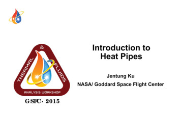
IntroductionThis application guide is written to assist the designer in Geothermal heat pump design. It is acompanion guide to McQuay’s Catalog 330-1, Water Source Heat Pump Design Manual, whichdiscusses Boiler/Tower heat pump design. It can be downloaded from www.mcquay.com or contactyour local McQuay representative.For the most comprehensive guide to Geothermal heat pump design, it is recommended thatdesigners refer to Ground-Source Heat Pump Systems: Design of Geothermal Systems forCommercial and Institutional Systems, available from the American Society Of Heating, Airconditioning and Refrigeration Engineers (ASHRAE) at www.ashrae.org.Why are Geothermal Heat Pumps So Effective?It is not unusual to hear how Geothermal water source heat pump systems are very energy efficient,but what is it that makes them so efficient? Both Boiler/Tower and Geothermal systems use basicallythe same heat pump equipment and the COPs (Coefficient of Performance) are similar when rated atthe same conditions. A Geothermal system’s summer design conditions are close to a Boiler/Towersystem’s (90 F loop design temperature is common), but the winter design temperature is often muchlower. While it is true that Geothermal systems do not have a boiler or a cooling tower, there is alarge water pressure drop in the ground loop that requires a large pump horsepower.One advantage of the system is the closed loop water source heat pump design. The concept allowsenergy that is not required in some areas of the building (cooling load) to be moved and used in areasthat do require energy (heating load). For many applications, water source heat pump systems matchor exceed the performance of even the most sophisticated VAV air systems.Figure 1 – Comparison of Boiler/Tower vs. Geothermal Heat Pumps450000Loop OperatingTemperatures400000350000While it is not unusual for GeothermalandBoiler/Towersummer design loop temperaturesto be around 90 F, Geothermalsystems can have a winter designcondition below freezing (25 F to30 F) in cooler climates. MostBoiler/Tower systems are designed for 60 F to 70 PumpsCoolerBoilerThe real energy savings do notcome from design conditions, butfrom part load operating performance. Even in colder climates, most heat pumps used in commercialapplications operate in cooling most of the time. This is particularly true for units serving core areasof a building. The colder the loop is in cooling, the better the heat pump performance (usuallymeasured as EER or Energy Efficiency Ratio). Because Boiler/Tower systems maintain the looptemperature above 60 to 70 F, the heat pumps have an EER around 22. Geothermal systems allowthe loop temperature to be potentially much cooler and the EER for the heat pumps can be as high as36.Boiler/TowerGeothermalIn addition, the loop temperature over the course of the year is much cooler for Geothermal systems.Boiler/Tower systems will operate at design conditions as soon as there is a net heat gain in thebuilding which causes the loop temperature to rise. The cooling tower controls will not start to rejectheat until the loop temperature is near the cooling setpoint.Application Guide AG 31-0083
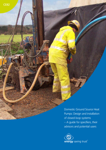
Evaluating the performance over the entire year requires annual energy analysis. Software tools suchas McQuay’s Energy Analyzer can be used to track the energy consumed by heat pumps inBoiler/Tower and Geothermal systems. Figure 1 shows annual energy usage for a 160,000 ft² highschool in Minneapolis. The Geothermal system uses 60% of the energy used by the Boiler/Towersystem. In this case, the savings are over 13,000/year.Cooling Tower and Boiler EnergyBoiler/Tower systems require some form of cooling tower (Either a closed circuit evaporative cooleror an open cooling tower with a heat exchanger). These devices reject heat to the atmosphere basedon the ambient wet bulb temperature. They consume power in two ways. First, their fans and pumpsuse electricity. Second, their water pressure drops must be accounted for when sizing the circulatingpumps. Figure 1 shows the annual energy usage for a closed circuit cooling tower to be 958 kWh/yr.Boilers are used in Boiler/Tower systems to maintain the loop temperature above the minimumsetpoint. Most of the required heat in a heat pump system comes from other heat pumps on the loopoperating in cooling. The actual number of hours a Boiler/Tower loop requires supplemental heat isvery small. In the example in Figure 1, the boiler actually ran only 1506 hours, mostly on weekends.When the boiler is required, it will consume either natural gas or electricity. Also, the boiler adds apressure drop to either the main loop or to a tertiary pump. The latter has the advantage that it onlyuses power when the boilers are required. Figure 1 shows the energy use by the boiler to be1,227,000 kBtu/yr (359,000 kWh/yr).It is not uncommon to use boilers for other heating loads in addition to maintaining the minimumloop temperature (i.e. the ventilation load and entrance heaters). In evaluating Geothermal andBoiler/Tower systems, how these loads are accommodated should be carefully considered.Pump WorkAt first glance, Geothermal systems would appear to require significantly larger pumps to meet thepressure drop from the ground loop. However, geothermal systems do not have a cooling tower or aboiler pressure drop. In addition to the loops being carefully designed to minimize pressure drops,the use of reverse return piping, common headers and carefully sized piping can all help to reduce thepressure drop. It is not unusual for a Geothermal system to be under 100 ft. of head and notsignificantly greater than a Boiler/Tower system.Geothermal systems tend to be designed with higher flow rates that result in higher pump work thanBoiler/Tower systems.Figure 2 – Constant vs. Variable 00000HeatpumpsConstant FlowPumpsVariable FlowASHRAEStandard90.1-2001,Energy Standard for Buildings ExceptLow Rise Residential Buildings,requires hydronic systems with a totalpump power exceeding 10 hp to bevariable flow (6.3.4), and that eachwater source heat pump have a twoposition isolating valve that closeswhen the compressor is not operating(6.3.4.4). Figure 2 shows the annualenergy savings from switching tovariable flow for the example shownin Figure 1. Variable flow offers anadditional 6,000/year in savings.The pump work is very high in constant flow heat pump systems because it is based on the sum ofthe flow rate requirements of all the connected heat pumps and the flow must be provided 24 hours aday. Switching to variable flow lowered the pump work by 80% in this example.4Application Guide AG 31-008
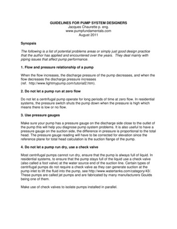
It is not recommended that the design flow rate or pipe size be reduced for variable flow systems as itis likely that most of the heat pumps may operate at the same time for a short period. This is longenough to cause nuisance trips because heat pumps cannot operate for any duration without flow.Ventilation LoadVentilation loads are often a significant load throughout the year. Water source heat pumps usuallyhave a dedicated system for heating and cooling the ventilation air. How effective this system is willdictate the overall performance of the building. Geothermal systems will often have advancedventilation systems that provide excellent energy savings and improve the overall building operatingcost. Ventilation systems are discussed in detail in Ventilation System Design (see page 33).Other BenefitsIn addition to the energy and operating cost savings, Geothermal systems offer many otheradvantages. Because there are no cooling towers and boilers, there is no need for sump heaters,tower water chemicals and make-up water.Decentralized DesignEach water source heat pump is in close proximity to the zone it serves, avoiding the large duct runsassociated with central air systems. An equipment failure only affects the zone where the failed unitis located. Central system equipment failures can drastically affect large portions of the building.Equipment can be changed to meet the specific needs of an occupant (i.e. in a retail environment, theunit can be sized to meet the load of a new tenant). Individual power metering is possible, allowingoccupants to control and pay their own energy costs. As the building is constructed, only a minimumamount of equipment needs to be provided until an occupant is found and the tenant design complete.Easy To ServiceWater source heat pumps are easy to service and do not require specialized training. The owner hasmany more options regarding maintenance and service. The refrigerant charges are small, whichhelps minimize safety requirements within the building.Small Mechanical RoomsWater source heat pump systems generally require smaller mechanical rooms than other HVACsystems. Geothermal system mechanical rooms are even smaller, requiring space for only thecirculating pumps, the main header and some chemical treatment equipment. This frees up moreuseable/leasable space for tenants or occupants.Figure 3 Typical Heat Pump ArrangementsFlexible EquipmentHeat pumps come in all shapes and sizes tomeet space requirements. Sizes range from ½ton to 30 tons. They can be located above theceiling, in a closet or in the occupied space.Indoor Air Quality (IAQ)Heat pump systems with properly designedventilation systems offer a good solution forindoor air quality (IAQ). The units can besupplied with double-sloped, cleanable drainpans and closed cell insulation. A proper ventilation system, along with the heat pumps, can helpcontrol moisture for good IAQ.Application Guide AG 31-0085
Loop Design TheoryLoop TypesA ground loop is a heat exchanger that either extracts or adds heat to the ground. The ground itself isnot a perfect heat sink/source because the energy added to the ground by the loop can change itstemperature over time. The principles of this interaction are common in all loop types and will bediscussed here. Geothermal systems come in several different configurations, each with its ownstrengths and weaknesses. These are discussed below.Figure 4 – Open LoopOpen vs. Closed LoopOpen loop systems draw ground waterdirectly into the building and heat/coolthe heat pumps with it. The systemrequires sufficient ground water tomeet the needs of the building.Ground water often has minerals andother contaminants in it thatdetrimentally affect the equipment.Open loop systems that use lake waterare also available, but should usefiltration equipment or secondary heatexchangers to deal with contaminates. Lake water, used in a open loop application, should be used inclimates where the entering water temperature is above 40 degrees F. The ground must have thecapacity to take open loop system discharge. These cannot be used below 40 F without the risk offreezing. In addition, open loop systems must allow for the increased pump head from thelake/ground water level to the heat pumps. Open loop systems are not common on commercial andinstitutional applications and will not be covered here.Closed loop systems have a dedicated fluid loop that is circulated through the ground or pond inorder to exchange energy. The ground/pond water and loop water do not mix. Closed loop systemsare further broken down into loop types.Figure 5 - Horizontal LoopHorizontal LoopA horizontal loop runs piping paralleland close to the surface.Theundisturbed ground temperature oftenchanges seasonally depending uponwhere the loops are installed.Horizontal loops are easier to install butrequiresignificantlymorearea(approximately 2500 ft²/ton) than otherloop types.6Application Guide AG 31-008
Figure 6 – Vertical LoopVertical LoopVertical loops run perpendicular to thesurface and the holes can be severalhundred feet deep. At these depths, theundisturbed ground temperature doesnot change throughout the year. Verticalloops only require approximately 250 to300 ft²/ton.Figure 7 – Surface Water LoopSurface Water LoopSurface water or pond loops use a bodyof water as the heat sink. Heat escapesthe water through surface evaporation,so the process is closely connected topond temperature and ambient wetbulb. In winter, when the pond couldbe frozen, heat transfer is dominated bycontact between the loops, the bottomwater and the soil surface at the bottomof the pond.Ground Loop FundamentalsFigure 8 – Typical Vertical U Tube Installation1The ground loop is a heat exchangerthat is similar to a cooling coil or anevaporator in a chiller. The goal is totransfer energy from the heat pumploop fluid to/from the ground.The purpose of loop design is toestimate the required loop length. Thisis best done with computer software,but a basic understanding of the processis helpful. The heating and coolingloads provide the designer with theenergy transfer rates for sizing the loop.The design supply fluid temperaturesmust be estimated. The larger the loopfor a known load, the cooler the supply fluid temperature will be. Lower fluid temperatures improve1Copyright 1997, American Society Of Heating, Air-conditioning and Refrigeration Engineers Inc.,www.ashrae.org. Reprinted by permission from Ground-Source Heat Pump Systems: Design ofGeothermal Systems for Commercial and Institutional BuildingsApplication Guide AG 31-0087
the heat pump performance and capacity. The designer must find a balance between heat pump fluidsupply temperature and the capital cost of the ground loop.At steady-state conditions, there is heat transfer from the heat pump fluid to the ground. Thetemperature difference between the ground and the fluid in the loop provides the impetus for theenergy to move. The resistance of the pipe, the grout and the ground restrict the energy movement asfollows:Qc L(tg – tw)/RWhereQc is the heat load (Btu/hr)L is the pipe length (feet)tg is the ground temperaturetw is the fluid temperatureR is the thermal resistance to heat transfer.The challenge in loop design is that the ground temperature does not stay constant. For horizontalloops, where the pipe is near the surface, the ground temperature can change seasonally with theweather. In all cases, the loop itself affects the ground temperature. For loop design, it is common tobreak the effects into three parts: Long Term Effect. This is the change in the ground temperature over many years. If thebuilding has a net heat gain or a net heat loss, the ground temperature will change. The moredensely placed the boreholes are, the larger the effect. Ground water moving through the borehole field can help remove energy and limit the long-term temperature change. For commercialapplications, the ground temperature generally climbs.An example of long term effect would be a 6 F average ground temperature rise over 10 yearsdue to the heat added to the borehole field. The penalty will not be present during the first year,but the heat build up will change the system performance over time. Annual Effect. Over the course of a year, the heat load on a bore field will change and this willaffect the ground temperature on a monthly basis. It is this “flywheel” effect that can actuallycause the warmest ground loop temperature to occur after the peak load has occurred. Short Term Effect. The actual load on the loop will affect the fluid supply temperature. Forexample, if the building were shut down, the fluid temperature would quickly become theground temperature. However, the loop temperature would be the ground temperature plus thedesign approach at design load. The actual hourly load also affects the borehole field’s ability todissipate heat. Therefore, the ground temperature will change with the hourly load. Most loopsizing software group the design day loads into four-hour intervals rather than using all 24 hours.These three effects must be estimated to find the required pipe length. The length may be establishedby the winter heating load requirement or the summer cooling load requirement. If a winter peakingload establishes the length, the designer should go back and evaluate the cooling performance withthe longer length. This will improve the summer performance and may allow smaller heat pumps tobe used for some spaces.8Application Guide AG 31-008
Borehole Thermal ResistanceMany factors affect the thermal resistance of the ground loop. These include the pipe properties,flow rate, backfill and grout properties, soil properties and fluid properties.Pipe PropertiesTable 1 – Equivalent Diameters and Thermal Resistances for Polyethylene U-Tubes2Pipe (Bore) Thermal Resistance (h ft F /Btu)U-Tube Dia.¾ in.(0.15 ft)1.0 in.(0.18 ft)1 1/4 in.(0.22 ft)1 1/2 in.(0.25 ft)SDR orScheduleFor WaterFlows Above2.0 US gpm20% Prop.Glycol Flow3.0 US gpm20% Prop.Glycol Flow5.0 US gpm20% Prop.Glycol Flow10.0 US gpmSDR 11SDR 9Sch 40SDR 11SDR 9Sch 40SDR 11SDR 9Sch 40SDR 11SDR 9Sch RNRNR0.090.110.090.090.110.08Based on using borehole cuttings for backfilling around u-tube. Use Table 2 corrections for other conditions.1Water flow must be at least 3.0 US gpm to avoid laminar flow for these cases.Table 1 shows thermal resistances for four common pipe sizes. Avoiding laminar flow at designconditions is important to provide good heat transfer. For water, the flow rate should be at least 2.0US gpm for ¾” through 1 ¼ ” pipe, and at least 3 US gpm for 1 ½”pipe to avoid laminar flow.Backfill and GroutsThe backfill also plays a major part in performance. Air gaps or separation should be avoided as air isa natural insulator. Grouting is the most common material for backfill. It can seal the borehole offfrom surface water penetration. Standard grout actually has a poor conductivity, so the bore holediameter should be minimized (Approximately 5” diameter) to limit the grout’s affect. There may belocal code requirements to grout the entire borehole, or the borehole may penetrate multiple aquifersthat need to remain isolated.2Copyright 1997, American Society Of Heating, Air-conditioning and Refrigeration Engineers Inc.,www.ashrae.org. Reprinted by permission from Ground-Source Heat PumpSystems: Design ofGeothermal Systems for Commercial and Institutional BuildingsApplication Guide AG 31-0089
Table 2 – Thermal Resistance Adjustments For Other Borehole Backfills or Grouts3(Add value to Base Resistances in )Natural Soil Cond.0.9 Btu/h ft F 1.7 Btu/h ft F 2.0Btu/h ft F 0.5Btu/h ft F 1.0Btu/h ft F 2.0Btu/h ft F 0.5Btu/h ft F 1.0Btu/h ft F 0.11 (NR)0.07-0.05-0.030.14 (NR)0.090.030.02-0.02-0.020.17 (NR)0.13 (NR)0.050.040.14 (NR)0.11 (NR)0.06-0.06-0.04-0.030.18 (NR)0.14 (NR)0.090.040.030.02-0.04-0.02-0.020.21 (NR)0.16 (NR)0.12 (NR)0.060.050.040.18 (NR)0.14 (NR)0.090.07-0.07-0.06-0.04-0.030.21 (NR)0.17 (NR)0.12 (NR)0.090.040.030.030.02-0.05-0.04-0.02-0.020.24 (NR)0.21 (NR)0.15 (NR)0.11 (NR)0.070.060.050.04Backfill or GroutConductivity4 in. Bore¾ in. U-tube1 in U-tube5 in. Bore¾ in. U-tube1 in U-tube1 1/4 in U-tube6 in. Bore¾ in. U-tube1 in U-tube1 1/4 in U-tube1 1/2 in U-tube1.3 Btu/h ft F 0.5Btu/h ft F (NR) Not RecommendedAir Gaps add 0.2 t o0.4 h ft F /Btu to Bore ResistanceNote some adjustments are negative, which indicates a thermal enhancement and a lower net thermal resistance compared tonatural backfills.Table 3 shows the thermal conductivities for enhanced grouts. Enhanced grouts can significantlyimprove the borehole performance, which can lead to fewer or shallower boreholes. However, it ismore costly. Each project is unique and a job-by-job analysis is required to evaluate whetherenhanced grouts will actually reduce the construction cost.Table 3 – Thermal Conductivities of Typical Grouts and Backfills4Grouts and Additivesk (Btu/h ft F )Thermal Enhanced Groutsk (Btu/h ft F )20% Bentonite30% BentoniteCement MortarConcrete @ 130/150 lb/ft³Concrete (50% quartz sand)0.420.430.40-0.450.60-0.801.1-1.720% Bentonite – 40% Quartzite30% Bentonite – 30% Quartzite30% Bentonite – 30% Iron Ore60% Quartzite – Flowable Fill(Cement Fly Ash Sand)0.850.70-0.750.451.07Soil PropertiesThe thermal conductivity of the soil at the site is required to estimate the ground loop performance.For large (over 50 tons) projects, the soil should be tested (refer to Ground Testing, page 26). Theadvantage to testing is that more accurate soil data will allow the designer to minimize the safetyfactor and reduce the number of holes. The savings from the reduced number of holes should morethan pay for the test.3Copyright 1997, American Society Of Heating, Air-conditioning and Refrigeration Engineers Inc.,www.ashrae.org. Reprinted by permission from Ground-Source Heat Pump Systems: Design ofGeothermal Systems for Commercial and Institutional Buildings4Copyright 1997, American Society Of Heating, Air-conditioning and Refrigeration Engineers Inc.,www.ashrae.org. Reprinted by permission from Ground-Source Heat Pump Systems: Design ofGeothermal Systems for Commercial and Institutional Buildings10Application Guide AG 31-008
Table 4 – Thermal Conductivity and Diffusivity of Sand and Clay Soils5SoilTypeDryDensity(lb/ft³)k5% Moistαk10% Moistαk15% Moistαk20% l Conductivity (k) - Btu/h ft F and Thermal Diffusivity (α) - ft²/dayCoarse grain 0.075 to 5 mm – Fine Grain less than 0.075 mmTable 4 shows the thermal properties for sand and clay soils, which range from 0.3 to 1.9 Btu/h ft F .Most soil is a combination of fine and coarse grain. A Sieve analysis can be used to determine thepercentage of each so that a weighted average can be developed to find an overall conductivity.Moisture content is a major factor, but sand or clay do not need to be heavily saturated to providegood conductivity.5Copyright 1997, American Society Of Heating, Air-conditioning and Refrigeration Engineers Inc.,www.ashrae.org. Reprinted by permission from Ground-Source Heat Pump Systems: Design ofGeothermal Systems for Commercial and Institutional BuildingsApplication Guide AG 31-00811
Table 5 – Thermal Properties of Rocks At 77 F6Rock TypeIgneous RocksGranite (10% Quartz)Granite (25% Quartz)AmphiboliteAndesiteBasaltGabbro (Cen. Plains)Gabbro (Rocky Mtns.)DioritesGrandioritesSedimentary RocksClaystoneDolomiteLimestoneRock SaltSandstoneSiltstoneWet Shale (25% Qrtz.)Wet Shale (No Qrtz.)Dry Shale (25% Qrtz.)Dry Shale (No Qrtz.)Metamorphic RocksGneissMarbleQuarziteSchistSlate%1Occurrencein Earth’sCrustk - All 2Ther. Con.Btu/h ft 1.2-2.60.9-4.55.1.K - 80% 3Ther.Con.Btu/h ft FcpSpec. HeatBtu/lb- FρDensitylb/ft 3α (k/ρ cp)Ther. Diff.ft .7-1.00.45-0.550.9-1.20.8-1.22.2-3.00.6-0.9Table 5 lists the thermal properties for rock. Again, there is a wide variation in performance.Because of its high porosity, rock generally has lower performance. The 80% range is moreconservative and is recommended unless the designer has detailed information.Effects of Ground WaterGround water movement through the bore hole field can have a large impact on its performance.Ground water recharge (vertical flow) and ground water movement (horizontal flow) can all carryaway large amounts of energy. Evaporation can also cool the surface soil and improve horizontalloop performance.Fluid PropertiesIn colder climates, where the supply loop temperature may be less than 40ºF, antifreeze will berequired. Antifreeze will change the properties of the loop fluid. Refer to APPENDIX l forproperties of various antifreezes. Adding antifreeze will generally lower the thermal capacity of thefluid and increase the viscosity. The latter will increase pump work. Also, the Reynolds number willdecrease and raise the flow rate at which laminar flow begins. To offset these effects, the design flow6Copyright 1997, American Society Of Heating, Air-conditioning and Refrigeration Engineers Inc.,www.ashrae.org. Reprinted by permission from Ground-Source Heat Pump Systems: Design ofGeothermal Systems for Commercial and Institutional Buildings12Application Guide AG 31-008
rate may need to be increased. Most loop design software programs include a r
Application Guide AG 31-008 3 Introduction This application guide is written to assist the designer in Geothermal heat pump design. It is a companion guide to McQuay’s Catalog 330-1, Water Source Heat Pump Design Manual, which discusses Boiler/