Transcription
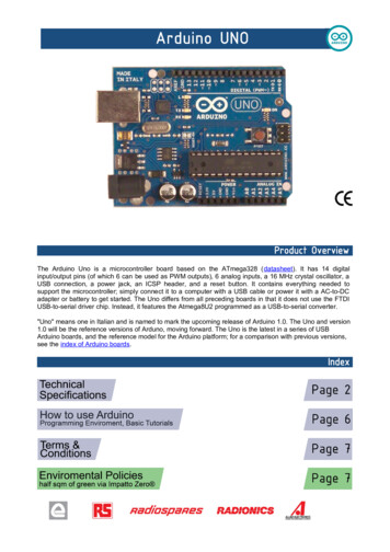
The Arduino Uno is a microcontroller board based on the ATmega328 (datasheet). It has 14 digitalinput/output pins (of which 6 can be used as PWM outputs), 6 analog inputs, a 16 MHz crystal oscillator, aUSB connection, a power jack, an ICSP header, and a reset button. It contains everything needed tosupport the microcontroller; simply connect it to a computer with a USB cable or power it with a AC-to-DCadapter or battery to get started. The Uno differs from all preceding boards in that it does not use the FTDIUSB-to-serial driver chip. Instead, it features the Atmega8U2 programmed as a USB-to-serial converter."Uno" means one in Italian and is named to mark the upcoming release of Arduino 1.0. The Uno and version1.0 will be the reference versions of Arduno, moving forward. The Uno is the latest in a series of USBArduino boards, and the reference model for the Arduino platform; for a comparison with previous versions,see the index of Arduino boards.
EAGLE files: arduino-duemilanove-uno-design.zip Schematic: arduino-uno-schematic.pdfMicrocontrollerOperating VoltageInput Voltage (recommended)Input Voltage (limits)Digital I/O PinsAnalog Input PinsDC Current per I/O PinDC Current for 3.3V PinFlash MemorySRAMEEPROMClock SpeedATmega3285V7-12V6-20V14 (of which 6 provide PWM output)640 mA50 mA32 KB of which 0.5 KB used bybootloader2 KB1 KB16 MHz
The Arduino Uno can be powered via the USB connection or with an external power supply. The powersource is selected automatically.External (non-USB) power can come either from an AC-to-DC adapter (wall-wart) or battery. The adaptercan be connected by plugging a 2.1mm center-positive plug into the board's power jack. Leads from abattery can be inserted in the Gnd and Vin pin headers of the POWER connector.The board can operate on an external supply of 6 to 20 volts. If supplied with less than 7V, however, the 5Vpin may supply less than five volts and the board may be unstable. If using more than 12V, the voltageregulator may overheat and damage the board. The recommended range is 7 to 12 volts.The power pins are as follows: VIN. The input voltage to the Arduino board when it's using an external power source (as opposed to5 volts from the USB connection or other regulated power source). You can supply voltage throughthis pin, or, if supplying voltage via the power jack, access it through this pin.5V. The regulated power supply used to power the microcontroller and other components on theboard. This can come either from VIN via an on-board regulator, or be supplied by USB or anotherregulated 5V supply.3V3. A 3.3 volt supply generated by the on-board regulator. Maximum current draw is 50 mA.GND. Ground pins.The Atmega328 has 32 KB of flash memory for storing code (of which 0,5 KB is used for the bootloader); Ithas also 2 KB of SRAM and 1 KB of EEPROM (which can be read and written with the EEPROM library).Each of the 14 digital pins on the Uno can be used as an input or output, using pinMode(), digitalWrite(), anddigitalRead() functions. They operate at 5 volts. Each pin can provide or receive a maximum of 40 mA andhas an internal pull-up resistor (disconnected by default) of 20-50 kOhms. In addition, some pins havespecialized functions: Serial: 0 (RX) and 1 (TX). Used to receive (RX) and transmit (TX) TTL serial data. TThese pins areconnected to the corresponding pins of the ATmega8U2 USB-to-TTL Serial chip .External Interrupts: 2 and 3. These pins can be configured to trigger an interrupt on a low value, arising or falling edge, or a change in value. See the attachInterrupt() function for details.PWM: 3, 5, 6, 9, 10, and 11. Provide 8-bit PWM output with the analogWrite() function.SPI: 10 (SS), 11 (MOSI), 12 (MISO), 13 (SCK). These pins support SPI communication, which,although provided by the underlying hardware, is not currently included in the Arduino language.LED: 13. There is a built-in LED connected to digital pin 13. When the pin is HIGH value, the LED ison, when the pin is LOW, it's off.
The Uno has 6 analog inputs, each of which provide 10 bits of resolution (i.e. 1024 different values). Bydefault they measure from ground to 5 volts, though is it possible to change the upper end of their rangeusing the AREF pin and the analogReference() function. Additionally, some pins have specializedfunctionality: I2C: 4 (SDA) and 5 (SCL). Support I2C (TWI) communication using the Wire library.There are a couple of other pins on the board: AREF. Reference voltage for the analog inputs. Used with analogReference().Reset. Bring this line LOW to reset the microcontroller. Typically used to add a reset button toshields which block the one on the board.See also the mapping between Arduino pins and Atmega328 ports.The Arduino Uno has a number of facilities for communicating with a computer, another Arduino, or othermicrocontrollers. The ATmega328 provides UART TTL (5V) serial communication, which is available ondigital pins 0 (RX) and 1 (TX). An ATmega8U2 on the board channels this serial communication over USBand appears as a virtual com port to software on the computer. The '8U2 firmware uses the standard USBCOM drivers, and no external driver is needed. However, on Windows, an *.inf file is required.The Arduino software includes a serial monitor which allows simple textual data to be sent to and from theArduino board. The RX and TX LEDs on the board will flash when data is being transmitted via the USB-toserial chip and USB connection to the computer (but not for serial communication on pins 0 and 1).A SoftwareSerial library allows for serial communication on any of the Uno's digital pins.The ATmega328 also support I2C (TWI) and SPI communication. The Arduino software includes a Wirelibrary to simplify use of the I2C bus; see the documentation for details. To use the SPI communication,please see the ATmega328 datasheet.The Arduino Uno can be programmed with the Arduino software (download). Select "Arduino Uno w/ATmega328" from the Tools Board menu (according to the microcontroller on your board). For details,see the reference and tutorials.The ATmega328 on the Arduino Uno comes preburned with a bootloader that allows you to upload new codeto it without the use of an external hardware programmer. It communicates using the original STK500protocol (reference, C header files).You can also bypass the bootloader and program the microcontroller through the ICSP (In-Circuit SerialProgramming) header; see these instructions for details.The ATmega8U2 firmware source code is available . The ATmega8U2 is loaded with a DFU bootloader,which can be activated by connecting the solder jumper on the back of the board (near the map of Italy) andthen resetting the 8U2. You can then use Atmel's FLIP software (Windows) or the DFU programmer (MacOS X and Linux) to load a new firmware. Or you can use the ISP header with an external programmer(overwriting the DFU bootloader).
Rather than requiring a physical press of the reset button before an upload, the Arduino Uno is designed in away that allows it to be reset by software running on a connected computer. One of the hardware flow controllines (DTR) of the ATmega8U2 is connected to the reset line of the ATmega328 via a 100 nanofaradcapacitor. When this line is asserted (taken low), the reset line drops long enough to reset the chip. TheArduino software uses this capability to allow you to upload code by simply pressing the upload button in theArduino environment. This means that the bootloader can have a shorter timeout, as the lowering of DTRcan be well-coordinated with the start of the upload.This setup has other implications. When the Uno is connected to either a computer running Mac OS X orLinux, it resets each time a connection is made to it from software (via USB). For the following half-second orso, the bootloader is running on the Uno. While it is programmed to ignore malformed data (i.e. anythingbesides an upload of new code), it will intercept the first few bytes of data sent to the board after aconnection is opened. If a sketch running on the board receives one-time configuration or other data when itfirst starts, make sure that the software with which it communicates waits a second after opening theconnection and before sending this data.The Uno contains a trace that can be cut to disable the auto-reset. The pads on either side of the trace canbe soldered together to re-enable it. It's labeled "RESET-EN". You may also be able to disable the auto-resetby connecting a 110 ohm resistor from 5V to the reset line; see this forum thread for details.The Arduino Uno has a resettable polyfuse that protects your computer's USB ports from shorts andovercurrent. Although most computers provide their own internal protection, the fuse provides an extra layerof protection. If more than 500 mA is applied to the USB port, the fuse will automatically break the connectionuntil the short or overload is removed.The maximum length and width of the Uno PCB are 2.7 and 2.1 inches respectively, with the USB connectorand power jack extending beyond the former dimension. Three screw holes allow the board to be attached toa surface or case. Note that the distance between digital pins 7 and 8 is 160 mil (0.16"), not an even multipleof the 100 mil spacing of the other pins.
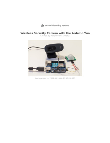
Arduino can sense the environment by receiving input from a variety of sensors and can affect itssurroundings by controlling lights, motors, and other actuators. The microcontroller on the board isprogrammed using the Arduino programming language (based on Wiring) and the Arduinodevelopment environment (based on Processing). Arduino projects can be stand-alone or they cancommunicate with software on running on a computer (e.g. Flash, Processing, MaxMSP).Arduino is a cross-platoform program. You’ll have to follow different instructions for your personalOS. Check on the Arduino site for the latest instructions. http://arduino.cc/en/Guide/HomePageOnce you have downloaded/unzipped the arduino IDE, you can Plug the Arduino to your PC via USB cable.Now you’re actually ready to “burn” yourfirst program on the arduino board. Toselect “blink led”, the physical translationof the well known programming “helloworld”, selectFile Sketchbook Arduino-0017 Examples Digital BlinkOnce you have your skecth you’llsee something very close to thescreenshot on the right.In Tools Board selectNow you have to go toTools SerialPortand select the right serial port, theone arduino is attached to.
1.Warranties1.1 The producer warrants that its products will conform to the Specifications. This warranty lasts for one (1) years from the date of the sale. Theproducer shall not be liable for any defects that are caused by neglect, misuse or mistreatment by the Customer, including improper installation or testing,or for any products that have been altered or modified in any way by a Customer. Moreover, The producer shall not be liable for any defects that result fromCustomer's design, specifications or instructions for such products. Testing and other quality control techniques are used to the extent the producer deemsnecessary.1.2 If any products fail to conform to the warranty set forth above, the producer's sole liability shall be to replace such products. The producer's liabilityshall be limited to products that are determined by the producer not to conform to such warranty. If the producer elects to replace such products, theproducer shall have a reasonable time to replacements. Replaced products shall be warranted for a new full warranty period.1.3 EXCEPT AS SET FORTH ABOVE, PRODUCTS ARE PROVIDED "AS IS" AND "WITH ALL FAULTS." THE PRODUCER DISCLAIMS ALL OTHERWARRANTIES, EXPRESS OR IMPLIED, REGARDING PRODUCTS, INCLUDING BUT NOT LIMITED TO, ANY IMPLIED WARRANTIES OFMERCHANTABILITY OR FITNESS FOR A PARTICULAR PURPOSE1.4 Customer agrees that prior to using any systems that include the producer products, Customer will test such systems and the functionality of theproducts as used in such systems. The producer may provide technical, applications or design advice, quality characterization, reliability data or otherservices. Customer acknowledges and agrees that providing these services shall not expand or otherwise alter the producer's warranties, as set forthabove, and no additional obligations or liabilities shall arise from the producer providing such services.1.5 The Arduino products are not authorized for use in safety-critical applications where a failure of the product would reasonably be expected to causesevere personal injury or death. Safety-Critical Applications include, without limitation, life support devices and systems, equipment or systems for theoperation of nuclear facilities and weapons systems. Arduino products are neither designed nor intended for use in military or aerospace applications orenvironments and for automotive applications or environment. Customer acknowledges and agrees that any such use of Arduino products which is solelyat the Customer's risk, and that Customer is solely responsible for compliance with all legal and regulatory requirements in connection with such use.1.6 Customer acknowledges and agrees that it is solely responsible for compliance with all legal, regulatory and safety-related requirements concerning itsproducts and any use of Arduino products in Customer's applications, notwithstanding any applications-related information or support that may beprovided by the producer.2.IndemnificationThe Customer acknowledges and agrees to defend, indemnify and hold harmless the producer from and against any and all third-party losses, damages,liabilities and expenses it incurs to the extent directly caused by: (i) an actual breach by a Customer of the representation and warranties made under thisterms and conditions or (ii) the gross negligence or willful misconduct by the Customer.3.Consequential Damages WaiverIn no event the producer shall be liable to the Customer or any third parties
The Arduino Uno is a microcontroller board based on the ATmega328 (datasheet). It has 14 digital input/output pins (of which 6 can be used as PWM outputs), 6 analog inputs, a 16 MHz crystal oscillator, a USB connection, a power jack, an ICSP header, and a reset button. It contains everything needed to support the microcontroller; simply connect it to a computer with a USB cable or power it .