Transcription
User ManualMicro810 Programmable ControllersCatalog Numbers 2080-LC10-12AWA, 2080-LC10-12QWB, 2080-LC10-12QBB, 2080-LC10-12DWD
Important User InformationSolid-state equipment has operational characteristics differing from those of electromechanical equipment. SafetyGuidelines for the Application, Installation and Maintenance of Solid State Controls (publication SGI-1.1 available fromyour local Rockwell Automation sales office or online at http://www.rockwellautomation.com/literature/) describes someimportant differences between solid-state equipment and hard-wired electromechanical devices. Because of this difference,and also because of the wide variety of uses for solid-state equipment, all persons responsible for applying this equipmentmust satisfy themselves that each intended application of this equipment is acceptable.In no event will Rockwell Automation, Inc. be responsible or liable for indirect or consequential damages resulting fromthe use or application of this equipment.The examples and diagrams in this manual are included solely for illustrative purposes. Because of the many variables andrequirements associated with any particular installation, Rockwell Automation, Inc. cannot assume responsibility orliability for actual use based on the examples and diagrams.No patent liability is assumed by Rockwell Automation, Inc. with respect to use of information, circuits, equipment, orsoftware described in this manual.Reproduction of the contents of this manual, in whole or in part, without written permission of Rockwell Automation,Inc., is prohibited.Throughout this manual, when necessary, we use notes to make you aware of safety considerations.WARNING: Identifies information about practices or circumstances that can cause an explosion in a hazardousenvironment, which may lead to personal injury or death, property damage, or economic loss.ATTENTION: Identifies information about practices or circumstances that can lead to personal injury or death,property damage, or economic loss. Attentions help you identify a hazard, avoid a hazard, and recognize theconsequenceSHOCK HAZARD: Labels may be on or inside the equipment, for example, a drive or motor, to alert people thatdangerous voltage may be present.BURN HAZARD: Labels may be on or inside the equipment, for example, a drive or motor, to alert people thatsurfaces may reach dangerous temperatures.ARC FLASH HAZARD: Labels may be on or inside the equipment, for example, a motor control center, to alert peopleto potential Arc Flash. Arc Flash will cause severe injury or death. Wear proper Personal Protective Equipment (PPE).Follow ALL Regulatory requirements for safe work practices and for Personal Protective Equipment (PPE).IMPORTANTIdentifies information that is critical for successful application and understanding of the product.Allen-Bradley, Micro800, Micro810, Connected Components Workbench, Rockwell Software, Rockwell Automation, and TechConnect are trademarks of Rockwell Automation, Inc.Trademarks not belonging to Rockwell Automation are property of their respective companies.
PrefaceRead this preface to familiarize yourself with the rest of the manual. It providesinformation concerning: who should use this manual the purpose of this manual related documentationWho Should Use thisManualUse this manual if you are responsible for designing, installing, programming, ortroubleshooting control systems that use Micro800 controllers.You should have a basic understanding of electrical circuitry and familiarity withrelay logic. If you do not, obtain the proper training before using this product.Purpose of this ManualThis manual is a reference guide for Micro800 controllers, plug-in modules andaccessories. It describes the procedures you use to install, wire, and troubleshootyour controller. This manual: explains how to install and wire your controllers gives you an overview of the Micro800 controller systemRefer to the Online Help provided with Connected Components Workbench software for more information on programming your Micro800 controller.Additional ResourcesThese documents contain additional information concerning related RockwellAutomation products.ResourceDescriptionMicro800 Programmable Controller External ACPower Supply Installation 2080-IN001Information on mounting and wiring the optionalexternal power supply.Micro810 USB Adapter Plug-in Module WiringDiagrams 2080-WD001Information on mounting and wiring theMicro810 USB Adapter Plug-in Module.Micro800 1.5" LCD Display and Keypad ModuleWiring Diagrams 2080-WD009Information on mounting and wiring theMicro800 1.5" LCD Display and Keypad Module.Micro800 Programmable Controllers GeneralInstructions 2080-RM001Information on instruction sets for developingprograms for use in Micro800 control systems.Industrial Automation Wiring and GroundingGuidelines, publication 1770-4.1Provides general guidelines for installing aRockwell Automation industrial system.Product Certifications website, cation/Provides declarations of conformity, certificates,and other certification details.Rockwell Automation Publication 2080-UM001F-EN-E - November 2016iii
PrefaceResourceDescriptionApplication Considerations for Solid-StateControls SGI-1.1A description of important differences betweensolid-state programmable controller productsand hard-wired electromechanical devices.National Electrical Code - Published by theNational Fire Protection Association of Boston,MA.An article on wire sizes and types for groundingelectrical equipment.Allen-Bradley Industrial Automation GlossaryAG-7.1A glossary of industrial automation terms andabbreviations.You can view or download publications athttp://www.rockwellautomation.com/literature/. To order paper copies oftechnical documentation, contact your local Rockwell Automation distributor orsales representative.You can download the latest version of Connected Components Workbench foryour Micro800 at the URL ducts-technologies/connectedcomponents/.ivRockwell Automation Publication 2080-UM001F-EN-E - November 2016
Table of ContentsPrefaceWho Should Use this Manual . . . . . . . . . . . . . . . . . . . . . . . . . . . . . . . . . . . . . . iiiPurpose of this Manual . . . . . . . . . . . . . . . . . . . . . . . . . . . . . . . . . . . . . . . . . . . . iiiAdditional Resources . . . . . . . . . . . . . . . . . . . . . . . . . . . . . . . . . . . . . . . . . . . . . . iiiChapter 1Hardware OverviewHardware Features . . . . . . . . . . . . . . . . . . . . . . . . . . . . . . . . . . . . . . . . . . . . . . . . . 1Micro810 12-Point Controllers. . . . . . . . . . . . . . . . . . . . . . . . . . . . . . . . . . 1Chapter 2About Your ControllerProgramming Software for Micro800 Controllers. . . . . . . . . . . . . . . . . . . . . 3Obtain Connected Components Workbench. . . . . . . . . . . . . . . . . . . . . 3Use Connected Components Workbench . . . . . . . . . . . . . . . . . . . . . . . . 3Agency Certifications. . . . . . . . . . . . . . . . . . . . . . . . . . . . . . . . . . . . . . . . . . . . . . . 3Compliance to European Union Directives. . . . . . . . . . . . . . . . . . . . . . . . . . . 3EMC Directive. . . . . . . . . . . . . . . . . . . . . . . . . . . . . . . . . . . . . . . . . . . . . . . . . 4Low Voltage Directive . . . . . . . . . . . . . . . . . . . . . . . . . . . . . . . . . . . . . . . . . . 4Installation Considerations . . . . . . . . . . . . . . . . . . . . . . . . . . . . . . . . . . . . . . . . . 4Environment and Enclosure . . . . . . . . . . . . . . . . . . . . . . . . . . . . . . . . . . . . . 6Preventing Electrostatic Discharge . . . . . . . . . . . . . . . . . . . . . . . . . . . . . . . 6Safety Considerations . . . . . . . . . . . . . . . . . . . . . . . . . . . . . . . . . . . . . . . . . . . . . . 6North American Hazardous Location Approval. . . . . . . . . . . . . . . . . . . 7Disconnecting Main Power. . . . . . . . . . . . . . . . . . . . . . . . . . . . . . . . . . . . . . 7Safety Circuits . . . . . . . . . . . . . . . . . . . . . . . . . . . . . . . . . . . . . . . . . . . . . . . . . 8Power Distribution . . . . . . . . . . . . . . . . . . . . . . . . . . . . . . . . . . . . . . . . . . . . 8Periodic Tests of Master Control Relay Circuit . . . . . . . . . . . . . . . . . . . 8Power Considerations . . . . . . . . . . . . . . . . . . . . . . . . . . . . . . . . . . . . . . . . . . . . . . 9Isolation Transformers. . . . . . . . . . . . . . . . . . . . . . . . . . . . . . . . . . . . . . . . . . 9Power Supply Inrush. . . . . . . . . . . . . . . . . . . . . . . . . . . . . . . . . . . . . . . . . . . . 9Loss of Power Source . . . . . . . . . . . . . . . . . . . . . . . . . . . . . . . . . . . . . . . . . . . 9Input States on Power Down . . . . . . . . . . . . . . . . . . . . . . . . . . . . . . . . . . 10Other Types of Line Conditions . . . . . . . . . . . . . . . . . . . . . . . . . . . . . . . 10Preventing Excessive Heat . . . . . . . . . . . . . . . . . . . . . . . . . . . . . . . . . . . . . . . . 10Master Control Relay. . . . . . . . . . . . . . . . . . . . . . . . . . . . . . . . . . . . . . . . . . . . . 10Using Emergency-Stop Switches . . . . . . . . . . . . . . . . . . . . . . . . . . . . . . . 11Schematic (Using IEC Symbols) . . . . . . . . . . . . . . . . . . . . . . . . . . . . . . . 13Schematic (Using ANSI/CSA Symbols) . . . . . . . . . . . . . . . . . . . . . . . . 14Chapter 3Install Your ControllerController Mounting Dimensions . . . . . . . . . . . . . . . . . . . . . . . . . . . . . . . . .Mounting Dimensions . . . . . . . . . . . . . . . . . . . . . . . . . . . . . . . . . . . . . . . .Module Spacing . . . . . . . . . . . . . . . . . . . . . . . . . . . . . . . . . . . . . . . . . . . . . .DIN Rail Mounting . . . . . . . . . . . . . . . . . . . . . . . . . . . . . . . . . . . . . . . . . .Rockwell Automation Publication 2080-UM001F-EN-E - November 201615151515v
Table of ContentsPanel Mounting . . . . . . . . . . . . . . . . . . . . . . . . . . . . . . . . . . . . . . . . . . . . . . 16Chapter 4Wire Your ControllerWiring Requirements . . . . . . . . . . . . . . . . . . . . . . . . . . . . . . . . . . . . . . . . . . . .Use Surge Suppressors . . . . . . . . . . . . . . . . . . . . . . . . . . . . . . . . . . . . . . . . . . . .Recommended Surge Suppressors . . . . . . . . . . . . . . . . . . . . . . . . . . . . . .Ground the Controller. . . . . . . . . . . . . . . . . . . . . . . . . . . . . . . . . . . . . . . . . . . .Wiring Diagrams . . . . . . . . . . . . . . . . . . . . . . . . . . . . . . . . . . . . . . . . . . . . . . . . .Controller I/O Wiring. . . . . . . . . . . . . . . . . . . . . . . . . . . . . . . . . . . . . . . . . . . .Minimize Electrical Noise . . . . . . . . . . . . . . . . . . . . . . . . . . . . . . . . . . . . .Analog Channel Wiring Guidelines . . . . . . . . . . . . . . . . . . . . . . . . . . . .Minimize Electrical Noise on Analog Channels . . . . . . . . . . . . . . . . .Ground Your Analog Cable . . . . . . . . . . . . . . . . . . . . . . . . . . . . . . . . . . .Wiring Examples . . . . . . . . . . . . . . . . . . . . . . . . . . . . . . . . . . . . . . . . . . . . .1717192020212122222323Chapter 5TroubleshootingStatus Indicators on the Controller . . . . . . . . . . . . . . . . . . . . . . . . . . . . . . . .Micro810 Controllers. . . . . . . . . . . . . . . . . . . . . . . . . . . . . . . . . . . . . . . . .Status Indicators on the LCD Module . . . . . . . . . . . . . . . . . . . . . . . . . . . . .Error codes . . . . . . . . . . . . . . . . . . . . . . . . . . . . . . . . . . . . . . . . . . . . . . . . . . . . . .Fault Types . . . . . . . . . . . . . . . . . . . . . . . . . . . . . . . . . . . . . . . . . . . . . . . . . .Corrective Action for Recoverable and Non-recoverable Faults . . .Controller Fault Recovery Model . . . . . . . . . . . . . . . . . . . . . . . . . . . . . . . . . .Calling Rockwell Automation for Assistance. . . . . . . . . . . . . . . . . . . . . . . .2525252626343536Chapter 6Program Execution in Micro800 Configure and Program Your Micro810 Controller . . . . . . . . . . . . . . . . . 37Overview of Program Execution . . . . . . . . . . . . . . . . . . . . . . . . . . . . . . . . . . .Execution Rules . . . . . . . . . . . . . . . . . . . . . . . . . . . . . . . . . . . . . . . . . . . . . .Power Up and First Scan . . . . . . . . . . . . . . . . . . . . . . . . . . . . . . . . . . . . . .Periodic Execution of Programs . . . . . . . . . . . . . . . . . . . . . . . . . . . . . . . .Memory Allocation. . . . . . . . . . . . . . . . . . . . . . . . . . . . . . . . . . . . . . . . . . . . . . .Guidelines and Limitations. . . . . . . . . . . . . . . . . . . . . . . . . . . . . . . . . . . . . . . .373839404041Chapter 7Controller SecurityviExclusive Access . . . . . . . . . . . . . . . . . . . . . . . . . . . . . . . . . . . . . . . . . . . . . . . . . .Password Protection . . . . . . . . . . . . . . . . . . . . . . . . . . . . . . . . . . . . . . . . . . . . . .Compatibility . . . . . . . . . . . . . . . . . . . . . . . . . . . . . . . . . . . . . . . . . . . . . . . . . . . .Work with a Locked Controller . . . . . . . . . . . . . . . . . . . . . . . . . . . . . . . . . . .Upload from a Password-Protected Controller . . . . . . . . . . . . . . . . . .Debug a Password-Protected Controller . . . . . . . . . . . . . . . . . . . . . . . .434344444545Rockwell Automation Publication 2080-UM001F-EN-E - November 2016
Chapter 1Download to a Password-Protected Controller. . . . . . . . . . . . . . . . . .Transfer Controller Program and Lock Receiving Controller. . . . .Back Up and Restore a Password-Protected Controller . . . . . . . . . .Configure Controller Password . . . . . . . . . . . . . . . . . . . . . . . . . . . . . . . . . . .Recover from a Lost Password . . . . . . . . . . . . . . . . . . . . . . . . . . . . . . . . . . . . .4545464747Appendix ASpecificationsMicro810 Controllers . . . . . . . . . . . . . . . . . . . . . . . . . . . . . . . . . . . . . . . . . . . . 49Micro800 Programmable Controller External AC Power Supply . 56Appendix BAbout AccessoriesAccessories . . . . . . . . . . . . . . . . . . . . . . . . . . . . . . . . . . . . . . . . . . . . . . . . . . . . . .External AC Power Supply . . . . . . . . . . . . . . . . . . . . . . . . . . . . . . . . . . . .1.5" LCD Display and Keypad Module . . . . . . . . . . . . . . . . . . . . . . . . .USB Adapter. . . . . . . . . . . . . . . . . . . . . . . . . . . . . . . . . . . . . . . . . . . . . . . . .57575860Appendix CQuickstartsConfigure LCD Password . . . . . . . . . . . . . . . . . . . . . . . . . . . . . . . . . . . . . . . .Activate Password . . . . . . . . . . . . . . . . . . . . . . . . . . . . . . . . . . . . . . . . . . . .Deactivate Password . . . . . . . . . . . . . . . . . . . . . . . . . . . . . . . . . . . . . . . . .Change Password. . . . . . . . . . . . . . . . . . . . . . . . . . . . . . . . . . . . . . . . . . . . .Delete Password . . . . . . . . . . . . . . . . . . . . . . . . . . . . . . . . . . . . . . . . . . . . .Configure Controller Password . . . . . . . . . . . . . . . . . . . . . . . . . . . . . . . . . . .Set Controller Password . . . . . . . . . . . . . . . . . . . . . . . . . . . . . . . . . . . . . .Change Password. . . . . . . . . . . . . . . . . . . . . . . . . . . . . . . . . . . . . . . . . . . . .Clear Password . . . . . . . . . . . . . . . . . . . . . . . . . . . . . . . . . . . . . . . . . . . . . . .Use the Micro810 Smart Relay Functionality . . . . . . . . . . . . . . . . . . . . . . .Smart Relay Block Execution Order. . . . . . . . . . . . . . . . . . . . . . . . . . . .Navigate the LCD Display . . . . . . . . . . . . . . . . . . . . . . . . . . . . . . . . . . . .Configure Count-Up (CTU) . . . . . . . . . . . . . . . . . . . . . . . . . . . . . . . . .Test the CTU Predefined Function . . . . . . . . . . . . . . . . . . . . . . . . . . . .Configure On-delay Timing (TON) . . . . . . . . . . . . . . . . . . . . . . . . . . .Test the TON Predefined Function. . . . . . . . . . . . . . . . . . . . . . . . . . . .Configure DOY . . . . . . . . . . . . . . . . . . . . . . . . . . . . . . . . . . . . . . . . . . . . . .Test the DOY Predefined Function . . . . . . . . . . . . . . . . . . . . . . . . . . . .Configure TOW . . . . . . . . . . . . . . . . . . . . . . . . . . . . . . . . . . . . . . . . . . . . .Test the TOW Predefined Function . . . . . . . . . . . . . . . . . . . . . . . . . . .Configure Countdown (CTD) . . . . . . . . . . . . . . . . . . . . . . . . . . . . . . . .Test the CTD Predefined Function . . . . . . . . . . . . . . . . . . . . . . . . . . . .Configure TONOFF . . . . . . . . . . . . . . . . . . . . . . . . . . . . . . . . . . . . . . . . .Test the TONOFF Predefined Function . . . . . . . . . . . . . . . . . . . . . . .Configure Pulse Timing (TP) . . . . . . . . . . . . . . . . . . . . . . . . . . . . . . . . .Rockwell Automation Publication 2080-UM001F-EN-E - November 9293vii
Table of ContentsTest the TP Predefined Function . . . . . . . . . . . . . . . . . . . . . . . . . . . . . . 94Configure TOF . . . . . . . . . . . . . . . . . . . . . . . . . . . . . . . . . . . . . . . . . . . . . . 95Test the TOF Predefined Function. . . . . . . . . . . . . . . . . . . . . . . . . . . . . 96Flash Update theMicro800 Firmware . . . . . . . . . . . . . . . . . . . . . . . . . . . . . . . . . . . . . . . . . . . . . . 98Establish Communication Between RSLinx and a Micro810 12-pointcontroller through USB . . . . . . . . . . . . . . . . . . . . . . . . . . . . . . . . . . . . . . . . . . 101Forcing I/O. . . . . . . . . . . . . . . . . . . . . . . . . . . . . . . . . . . . . . . . . . . . . . . . . . . . . 103Check if Forces (locks) are Enabled. . . . . . . . . . . . . . . . . . . . . . . . . . . . 103I/O Forces After a Power Cycle . . . . . . . . . . . . . . . . . . . . . . . . . . . . . . . 104Appendix DIPID Function BlockIndexviiiHow to AutoTune . . . . . . . . . . . . . . . . . . . . . . . . . . . . . . . . . . . . . . . . . . . . . .How Autotune Works . . . . . . . . . . . . . . . . . . . . . . . . . . . . . . . . . . . . . . .Troubleshooting an Autotune Process. . . . . . . . . . . . . . . . . . . . . . . . . . . . .PID Application Example . . . . . . . . . . . . . . . . . . . . . . . . . . . . . . . . . . . . . . . .PID Code Sample . . . . . . . . . . . . . . . . . . . . . . . . . . . . . . . . . . . . . . . . . . .108109109110112. . . . . . . . . . . . . . . . . . . . . . . . . . . . . . . . . . . . . . . . . . . . . . . . . . . . . . . . . . . . . . . . 115Rockwell Automation Publication 2080-UM001F-EN-E - November 2016
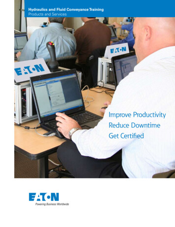
Chapter1Hardware OverviewHardware FeaturesThe Micro810 12-pt controllers are smart relays with high current relay outputmodels and can be configured through the embedded LCD display withoutprogramming software. It can also function as a micro PLC with the sameprogramming capabilities as the other Micro800 controllers.Micro810 controllers do not support Micro800 plug-in modules, but do supporta USB adapter, and an LCD module, which can be used as a backup memorymodule.24V DC powered controllers accommodate any 24V DC output power supplythat meets minimum specifications such as the optional Micro800 power supply(2080-LC10-12QWB, 2080-LC10-12QBB only).Micro810 12-Point Controllers1324547450526Controller DescriptionDescriptionDescription1Optional power supply5USB port (for use with USB Adapter only)2Status indicator6DIN rail mounting latch3Input terminal block7Output terminal block4Mounting screw hole/ mounting footRockwell Automation Publication 2080-UM001F-EN-E - November 20161
Chapter 1Hardware OverviewStatus IndicatorStateDuring Normal OperationDuring Firmware Update orProgram/Data TransferOffNo power applied to device,or in Fault modeNo power applied to device,or in Fault modeSolid greenDevice operating normallyProgram transfer successfulFlashing green Operating System errorFirmware update in progressMicro810 ControllersCatalog NumberPowerInputs120V AC2Outputs240V AC12 24V DC /V ACRelay842080-LC10-12QWB24V DC2080-LC10-12AWA120 240V AC2080-LC10-12QBB12 24V DC82080-LC10-12DWD12V DC8824 V DC SRCAnalog In 0 10V(shared with DC In)444444Rockwell Automation Publication 2080-UM001F-EN-E - November 2016
Chapter2About Your ControllerProgramming Software forMicro800 ControllersConnected Components Workbench is a set of collaborative tools supportingMicro800 controllers. It is based on Rockwell Automation and Microsoft VisualStudio technology and offers controller programming, device configuration andintegration with HMI editor. Use this software to program your controllers,configure your devices and design your operator interface applications.Connected Components Workbench provides a choice of IEC 61131-3programming languages (ladder diagram, function block diagram, structuredtext) with user defined function block support that optimizes machine control.Obtain Connected Components WorkbenchA free download is available ts-technologies/connectedcomponents/.Use Connected Components WorkbenchTo help you program your controller through the Connected ComponentsWorkbench software, you can refer to the Connected Components WorkbenchOnline Help (it comes with your software).Agency CertificationsCompliance to EuropeanUnion Directives UL Listed Industrial Control Equipment, certified for US and Canada.UL Listed for Class I, Division 2 Group A,B,C,D Hazardous Locations,certified for U.S. and Canada. CE marked for all applicable directives C-Tick marked for all applicable actsThis product has the CE mark and is approved for installation within theEuropean Union and EEA regions. It has been designed and tested to meet thefollowing directives.Rockwell Automation Publication 2080-UM001F-EN-E - November 20163
Chapter 2About Your ControllerEMC DirectiveThis product is tested to meet Council Directive 2004/108/EC ElectromagneticCompatibility (EMC) and the following standards, in whole or in part,documented in a technical construction file: EN 61131-2; Programmable Controllers (Clause 8, Zone A & B) EN 61131-2; Programmable Controllers (Clause 11) EN 61000-6-4EMC - Part 6-4: Generic Standards - Emission Standard for IndustrialEnvironments EN 61000-6-2EMC - Part 6-2: Generic Standards - Immunity for IndustrialEnvironmentsThis product is intended for use in an industrial environment.Low Voltage DirectiveThis product is tested to meet Council Directive 2006/95/EC Low Voltage, byapplying the safety requirements of EN 61131-2 Programmable Controllers, Part2 - Equipment Requirements and Tests.For specific information required by EN 61131-2, see the appropriate sections inthis publication, as well as the following Allen-Bradley publications: Industrial Automation Wiring and Grounding Guidelines for NoiseImmunity, publication 1770-4.1Installation ConsiderationsMost applications require installation in an industrial enclosure (PollutionDegree 2(1)) to reduce the effects of electrical interference (Over VoltageCategory II(2)) and environmental exposure. Locate your controller as far aspossible from power lines, load lines, and other sources of electrical noise such ashard-contact switches, relays, and AC motor drives. For more information onproper grounding guidelines, see the Industrial Automation Wiring andGrounding Guidelines publication 1770-4.1.(1) Pollution Degree 2 is an environment where normally only non-conductive pollution occurs except thatoccasionally temporary conductivity caused by condensation shall be expected.(2) Overvoltage Category II is the load level section of the electrical distribution system. At this level, transientvoltages are controlled and do not exceed the impulse voltage capability of the products insulation.4Rockwell Automation Publication 2080-UM001F-EN-E - November 2016
About Your ControllerChapter 2WARNING: If you insert or remove the module while power is on, an electrical arc can occur. This couldcause an explosion in hazardous location installations.Be sure that power is removed or the area is nonhazardous before proceeding.WARNING: The local programming terminal port is intended for temporary use only and must not beconnected or disconnected unless the area is assured to be nonhazardous.WARNING: When used in a Class I, Division 2, hazardous location, this equipment must be mounted in asuitable enclosure with proper wiring method that complies with the governing electrical codes.WARNING: If you connect or disconnect wiring while the field-side power is on, an electrical arc canoccur. This could cause an explosion in hazardous location installations. Be sure that power is removed orthe area is nonhazardous before proceeding.WARNING: The USB port is intended for temporary local programming purposes only and not intended forpermanent connection. If you connect or disconnect the USB cable with power applied to this module orany device on the USB network, an electrical arc can occur. This could cause an explosion in hazardouslocation installations.Be sure that power is removed or the area is nonhazardous before proceeding.The USB port is a nonincendive field wiring connection for Class I, Division2 Groups A, B, C and D.WARNING: Exposure to some chemicals may degrade the sealing properties of materials used in theRelays. It is recommended that the User periodically inspect these devices for any degradation ofproperties and replace the module if degradation is found.WARNING: To comply with the CE Low Voltage Directive (LVD), this equipment must be powered from asource compliant with the following:Safety Extra Low Voltage (SELV) or Protected Extra Low Voltage (PELV).WARNING: To comply with UL restrictions, this equipment must be powered from a source compliant withthe following:Class 2 or Limited Voltage/Current.WARNING: Do not wire more than 2 conductors on any single terminal.WARNING: Be careful when stripping wires. Wire fragments that fall into the controller could causedamage. Once wiring is complete, make sure the controller is free of all metal fragments.ATTENTION: Do not remove the protective debris strips until after the controller and all other equipmentin the panel near the module are mounted and wired. Remove strips before operating the controller. Failureto remove strips before operating can cause overheating.ATTENTION: Electrostatic discharge can damage semiconductor devices inside the module. Do not touchthe connector pins or other sensitive areas.ATTENTION: This product is intended to be mounted to a well-grounded mounting surface such as a metalpanel. Additional grounding connections from the power supply's mounting tabs or DIN rail (if used) are notrequired unless the mounting surface cannot be grounded. Refer to Industrial Automation Wiring andGrounding Guidelines, Allen-Bradley publication 1770-4.1, for additional information.ATTENTION: The USB cable is not to exceed 3.0 m (9.84 ft).Rockwell Automation Publication 2080-UM001F-EN-E - November 20165
Chapter 2About Your ControllerEnvironment and EnclosureThis equipment is intended for use in a Pollution Degree 2 industrial environment, inovervoltage Category II applications (as defined in IEC 60664-1), at altitudes up to2000 m (6562 ft) without derating.This equipment is considered Group 1, Class A industrial equipment according toIEC/CISPR 11. Without appropriate precautions, there may be difficulties withelectromagnetic compatibility in residential and other environments due toconducted and radiated disturbances.This equipment is supplied as open-type equipment. It must be mounted within anenclosure that is suitably designed for those specific environmental conditions thatwill be present and appropriately designed to prevent personal injury resulting fromaccessibility to live parts. The enclosure must have suitable flame-retardantproperties to prevent or minimize the spread of flame, complying with a flamespread rating of 5VA, V2, V1, V0 (or equivalent) if non-metallic. The interior of theenclosure must be accessible only by the use of a tool. Subsequent sections of thispublication may contain additional information regarding specific enclosure typeratings that are required to comply with certain product safety certifications.In addition to this publication, see: Industrial Automation Wiring and Grounding Guidelines, Rockwell Automationpublication 1770-4.1, for additional installation requirements. NEMA Standard 250 and IEC 60529, as applicable, for explanations of the degrees ofprotection provided by different types of enclosure.Preventing Electrostatic DischargeThis equipment is sensitive to electrostatic discharge, which can causeinternal damage and affect normal operation. Follow these guidelineswhen you handle this equipment: Safety Considerations6Touch a grounded object to discharge potential static.Wear an approved grounding wriststrap.Do not touch connectors or pins on component boards.Do not touch circuit components inside the equipment.Use a static-safe workstation, if available.Store the equipment in appropriate static-safe packaging when not in use.Safety considerations are an important element of proper system installation.Actively thinking about the safety of yourself and others, as well as the conditionof your equipment, is of primary importance. We recommend reviewing thefollowing safety considerations.Rockwell Automation Publication 2080-UM001F-EN-E - November 2016
About Your ControllerChapter 2North American Hazardous Location ApprovalThe following information applies when operating this equipmentin hazardous locations:Informations sur l’utilisation de cet équipement en environnementsdangereux:Products marked "CL I, DIV 2, GP A, B, C, D" are suitable for use in C
Connected Components Workbench is a set of collaborative tools supporting Micro800 controllers. It is based on Rockwell Automation and Microsoft Visual Studio technology and offers controller programming, device configuration and integration with HMI editor. Use this software to program your controllers,