Transcription
HILUXElectrical Wiring DiagramPub. No. DR114W
FOREWORDThis wiring diagram manual has been prepared to provideinformation on the electrical system of the HILUX.Applicable models: KUN15, 16, 25, 26 SeriesFor service specifications and repair procedures of the abovemodels other than those listed in this manual, refer to thefollowing manuals;Manual NameD HILUX Repair ManualD HILUX New Car FeaturesPub. No.DR172ENCF271EAll information in this manual is based on the latest productinformation at the time of publication. However, specificationsand procedures are subject to change without notice.NOTICEWhen handling supplemental restraint system components (removal,installation or inspection, etc.), always follow the direction given in the repairmanuals listed above to prevent accidents and supplemental restraintsystem malfunction.
HILUXELECTRICAL WIRING DIAGRAMSection CodePageINTRODUCTION . . . . . . . . . . . . . . . . . . . . . . . . . . . A . . . .2HOW TO USE THIS MANUAL . . . . . . . . . . . . . . . B . . . .3TROUBLESHOOTING . . . . . . . . . . . . . . . . . . . . . . C . . . .12ABBREVIATIONS . . . . . . . . . . . . . . . . . . . . . . . . . D . . . .17GLOSSARY OF TERMS AND SYMBOLS . . . . . E . . . .18RELAY LOCATIONS . . . . . . . . . . . . . . . . . . . . . . . F . . . .20ELECTRICAL WIRING ROUTING . . . . . . . . . . . G . . . .36SYSTEM CIRCUITS . . . . . . . . . . . . . . . . . . . . . . . . H . . . .59GROUND POINT . . . . . . . . . . . . . . . . . . . . . . . . . . . I . . . .182POWER SOURCE (Current Flow Chart) . . . . . J . . . .188CONNECTOR LIST . . . . . . . . . . . . . . . . . . . . . . . . K . . . .194PART NUMBER OF CONNECTORS . . . . . . . . . L . . . .202OVERALL ELECTRICAL WIRING DIAGRAM . M . . . .206E2004All rights reserved. This book may not bereproduced or copied, in whole or in part, withoutthe written permission of Toyota MotorCorporation.1
A INTRODUCTIONThis manual consists of the following 13 sections:No.SectionDescriptionINDEXIndex of the contents of this manual.INTRODUCTIONBrief explanation of each section.BHOW TO USE THISMANUALInstructions on how to use this manual.CTROUBLE–SHOOTINGDescribes the basic inspection procedures for electrical circuits.DABBREVIATIONSDefines the abbreviations used in this manual.EGLOSSARY OFTERMS ANDSYMBOLSDefines the symbols and functions of major parts.FRELAY LOCATIONSShows position of the Electronic Control Unit, Relays, Relay Block, etc.This section is closely related to the system circuit.GELECTRICALWIRING ROUTINGDescribes position of Parts Connectors, Splice points, Ground points, etc.This section is closely related to the system circuit.INDEXIndex of the system circuits.SYSTEM CIRCUITSElectrical circuits of each system are shown from the power supply through groundpoints. Wiring connections and their positions are shown and classified by codeaccording to the connection method. (Refer to the section, ”How to use this manual”).The ”System Outline” and ”Service Hints” useful for troubleshooting are also containedin this section.IGROUND POINTShows ground positions of all parts described in this manual.JPOWER SOURCE(Current Flow Chart)Describes power distribution from the power supply to various electrical loads.KCONNECTOR LISTDescribes the form of the connectors for the parts appeared in this book.This section is closely related to the system circuit.LPART NUMBER OFCONNECTORSIndicates the part number of the connectors used in this manual.MOVERALLELECTRICALWIRING DIAGRAMProvides circuit diagrams showing the circuit connections.AH2
HOW TO USE THIS MANUAL BThis manual provides information on the electrical circuits installed on vehicles bydividing them into a circuit for each system.The actual wiring of each system circuit is shown from the point where the powersource is received from the battery as far as each ground point. (All circuitdiagrams are shown with the switches in the OFF position.)When troubleshooting any problem, first understand the operation of the circuitwhere the problem was detected (see System Circuit section), the power sourcesupplying power to that circuit (see Power Source section), and the ground points(see Ground Point section). See the System Outline to understand the circuitoperation.When the circuit operation is understood, begin troubleshooting of the problemcircuit to isolate the cause. Use Relay Location and Electrical Wiring Routingsections to find each part, junction block and wiring harness connectors, wiringharness and wiring harness connectors, splice points, and ground points of eachsystem circuit. Internal wiring for each junction block is also provided for betterunderstanding of connection within a junction block.Wiring related to each system is indicated in each system circuit by arrows(from , to ). When overall connections are required, see the Overall ElectricalWiring Diagram at the end of this manual.3
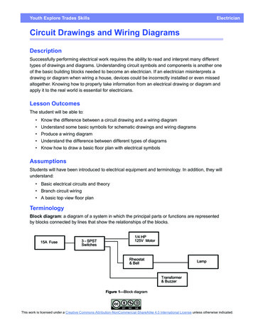
B HOW TO USE THIS MANUAL The system shown here is an EXAMPLE ONLY. It is different to the actualcircuit shown in the SYSTEM CIRCUITS SECTION.[A]Stop LightFrom Power Source System (See Page 66)15ASTOP7.5AGAUGE4IB2[B]1R L3 IB1 IB[C]2 IBR LL (S/D)R (W/G)W R[G]24[E]14 IE1[D]RearLightsS6Stop Light SW1I5[F]Y GG WL (S/D)G W13G WABS ECUC7CombinationMeter76[J](Shielded)R6Rear Combination Light LH2H17High MountedStop Light[K]B18W B1W BBV1W BW B1BO50[M][L]BLW BG R3W B[I]B18StopStopR7Rear Combination Light RHG R1G RBV1411G B[H]314G R24L4Light Failure Sensor8
B[A] : System Title[H] : Indicates the wiring color.Wire colors are indicated by an alphabetical code.[B] : Indicates a Relay Block. No shading is used andonly the Relay Block No. is shown to distinguish itfrom the J/BExample:Indicates Relay Block No.1B BlackW WhiteBR BrownL BlueVSB Sky Blue VioletR RedG GreenLG Light Green[C] : () is used to indicate different wiring andconnector, etc. when the vehicle model, enginetype, or specification is different.PYGR Gray[D] : Indicates related system.The first letter indicates the basic wire color and thesecond letter indicates the color of the stripe. Pink YellowO Orange[E] : Indicates the wiring harness and wiring harnessconnector. The wiring harness with male terminal isshown with arrows ().Outside numerals are pin numbers.Example:L–YL(Blue)[I]FemaleMale ()Y(Yellow): Indicates a wiring Splice Point (Codes are ”E” for theEngine Room, ”I” for the Instrument Panel, and ”B”for the Body).The first letter of the code for each wiring harnessand wiring harness connector(s) indicates thecomponent’s location, e.g, ”E” for the EngineCompartment, ”I” for the Instrument Panel andSurrounding area, and ”B” for the Body andSurrounding area.When more than one code has the first and secondletters in common, followed by numbers (e.g, IH1,IH2), this indicates the same type of wiring harnessand wiring harness connector.[F] : Represents a part (all parts are shown in sky blue).The code is the same as the code used in partsposition.[G] : Junction Block (The number in the circle is the J/BNo. and the connector code is shown beside it).Junction Blocks are shaded to clearly separatethem from other parts.Example:3C indicates thatit is insideJunction BlockNo.3The Location of splice Point I 5 is indicated by theshaded section.[J] : Indicates a shielded cable.[K] : Indicates the pin number of the connector.The numbering system is different for female andmale connectors.Example: Numbered in orderfrom upper left tolower rightFemaleNumbered in orderfrom upper right tolower leftMale[L] : Indicates a ground point.The first letter of the code for each ground point(s)indicates the component’s location, e.g, ”E” for theEngine Compartment, ”I” for the Instrument Paneland Surrounding area, and ”B” for the Body andSurrounding area.[M] : Page No.5
B HOW TO USE THIS MANUAL[N]System OutlineCurrent is applied at all times through the STOP fuse to TERMINAL 2 of the stop light SW.When the ignition SW is turned on, current flows from the GAUGE fuse to TERMINAL 8 of the light failure sensor, and also flowsthrough the rear lights warning light to TERMINAL 4 of the light failure sensor.Stop Light Disconnection WarningWhen the ignition SW is turned on and the brake pedal is pressed (Stop light SW on), if the stop light circuit is open, the currentflowing from TERMINAL 7 of the light failure sensor to TERMINALS 1, 2 changes, so the light failure sensor detects thedisconnection and the warning circuit of the light failure sensor is activated.As a result, the current flows from TERMINAL 4 of the light failure sensor to TERMINAL 11 to GROUND and turns the rear lightswarning light on. By pressing the brake pedal, the current flowing to TERMINAL 8 of the light failure sensor keeps the warningcircuit on and holds the warning light on until the ignition SW is turned off.[O]Service HintsS6 Stop Light SW2–1 : Closed with the brake pedal depressedL4 Light Failure Sensor1, 2, 7–Ground : Approx. 12 volts with the stop light SW on4, 8–Ground : Approx. 12 volts with the ignition SW at ON position11–Ground : Always continuity[P]: Parts LocationCodeSee PageSee PageCodeSee Page34L436R737H1736R637S635[Q]: Relay BlocksCode1[R]See Page18Relay Blocks (Relay Block Location)R/B No.1 (Instrument Panel Brace LH): Junction Block and Wire Harness ConnectorCodeSee PageJunction Block and Wire Harness (Connector Location)IB20Instrument Panel Wire and Instrument Panel J/B (Lower Finish Panel)3C22Instrument Panel Wire and J/B No.3 (Instrument Panel Brace LH)[S]: Connector Joining Wire Harness and Wire HarnessCodeSee PageJoining Wire Harness and Wire Harness (Connector Location)IE142Floor Wire and Instrument Panel Wire (Left Kick Panel)BV150Luggage Room Wire and Floor Wire (Luggage Room Left)[T]: Ground PointsCodeSee PageGround Points LocationBL50Under the Left Center PillarBO50Back Panel Center[U]: Splice PointsCodeI56CodeC7See Page44Wire Harness with Splice PointsCowl WireCodeB18See Page50Wire Harness with Splice PointsLuggage Room Wire
B[N] : Explains the system outline.[O] : Indicates values or explains the function for reference during troubleshooting.[P] : Indicates the reference page showing the position on the vehicle of the parts in the system circuit.Example : Part ”L4” (Light Failure Sensor) is on page 36 of the manual. The letter in the code is from the first letter of the part, and the number indicates its order in partsstarting with that letter.Example : L 4ÁÁParts is 4th in orderLight Failure Sensor[Q] : Indicates the reference page showing the position on the vehicle of Relay Block Connectors in the system circuit.Example : Connector ”1” is described on page 18 of this manual and is installed on the left side of the instrumentpanel.[R] : Indicates the reference page showing the position on the vehicle of J/B and Wire Harness in the system circuit.Example : Connector ”3C” connects the Instrument Panel Wire and J/B No.3. It is described on page 22 of thismanual, and is installed on the instrument panel left side.[S] : Indicates the reference page describing the wiring harness and wiring harness connector (the female wiringharness is shown first, followed by the male wiring harness).Example : Connector ”IE1” connects the floor wire (female) and Instrument panel wire (male). It is described onpage 42 of this manual, and is installed on the left side kick panel.[T] : Indicates the reference page showing the position of the ground points on the vehicle.Example : Ground point ”BO” is described on page 50 of this manual and is installed on the back panel center.[U] : Indicates the reference page showing the position of the splice points on the vehicle.Example : Splice point ”I5” is on the Cowl Wire Harness and is described on page 44 of this manual.7
B HOW TO USE THIS MANUALThe ground points circuit diagram shows the connections from all major parts to the respective ground points. Whentroubleshooting a faulty ground point, checking the system circuits which use a common ground may help you identifythe problem ground quickly. The relationship between ground points ( EA , IB and IC shown below) can also bechecked this way.I GROUND POINTW–BW–BFAN MAIN Relay5FAN MAIN Relay5A/C Control AssemblyW–BW–B5A/C Relay No.35W–BAO/D Main SWE3W–BA W–BAClockE3Blower MotorI6W–BA/C Relay No.2W–BACigarette LighterW–BBlower SWI6AW–BW–BAParking Brake SWE3J1JunctionConnectorW–BRadiator Fan MotorE373BW–BHeadlight Cleaner RelayE2W–BCombination MeterW–BW–BHeadlight LHE4E5W–BW–BE4W–BE5W–BFront Turn Signal Light LHW–BE4W–BW–BFront Fog Light LH33F133GW–BW–BBrake Fluid Level SWE6W–BDoor Lock Control SWW–BB42IA1Cruise Control ECURemote Control Mirror SWTurn Signal Flasher53EW–BFront Clearance Light LHW–BW–BI213DW–BFront Clearance Light RHW–BFront Fog Light RHW–BE4W–BFront Turn Signal Light RHCombination SW73CW–BHeadlight RHW–B63EW–BI4W–BDefogger SWI2W–BI2Combination SWB4W–BW–BW–B15 W–BW–BID1B5W–BW–BW–BUnlock Warning SWI510 EA2Door Lock Control RelayW–BI5W–BB4Door Lock Motor RHW–BW–BW–BDoor Courtesy SW RHI5W–BB5EAW–BI48 W–BIB1I8W–BW–BA/C AmplifierDoor Courtesy SW LHB5W–BDoor Lock Control SWB5W–BW–BW–BIdle–Up SWPower Window ControlRelayW–BW–BW–BBlower ResistorPower Window Master SWDoor Lock Motor LHW–B (4A–GZE)4443IC3W–BW–BBRRadio and PlayerFuel Control SWI54I5W–BWoofer Speaker AmplifierBRW–B4BRBR4I3BRCombination MeterI3BRFuel SenderW–B4BRBRAuto Antenna MotorCombination Meter5BA1W–BHEATER RelayIB 8ICThe system shown here is an EXAMPLE ONLY. It is different to the actual circuit shown in the SYSTEM CIRCUITS SECTION.
BThe ”Current Flow Chart” section, describes which parts each power source (fuses, fusible links, and circuit breakers)transmits current to. In the Power Source circuit diagram, the conditions when battery power is supplied to each systemare explained. Since all System Circuit diagrams start from the power source, the power source system must be fullyunderstood.J POWER SOURCE (Current Flow Chart)The chart below shows the route by which current flows from the battery to each electrical source(Fusible Link, Circuit Breaker, Fuse, etc.) and other parts.10A ECU–BShort Pin227.5A DOME15A EFI30A AM2BatteryFusible Link Block2610A HAZARD220A RADIO NO.1S2Starter10A HORN6100A ALT60A ABS5Engine Room R/B (See Page 20)20A10APageSystemFuseSTOPABSABS and Traction ControlCruise ControlElectronically Controlled TransmissionMultiplex Communication System194187180166210DOMECigarette LighterCombination MeterHeadlightInterior LightKey Reminder and Seat Belt WarningLight Auto Turn OffTheft Deterrent and Door Lock Control214230112122Power Source40A DOOR LOCK CB1.25B FL MAINWW27EB1WWBW2WI2W1I2W115A HAZ–RADIOW2W284AM12E76EB1W–RW–RAM27.5A AM2B1TAILRelay2BE7B2B4STARTER Relay3124I8Ignition SW4B–W2311W–B2B–W321G15A TAILG120A DEFOGB–Y2W–R11B22W–B2G–WBINJECTION Relay13IG12ACCB–OIG2B2E7R11BW7.5A DOMEWI250A MAINBW–L1WWWBattery3 EA2 1 EA1E7211E615A RAD CIGB–Y1 P–L1The system shown here is an EXAMPLE ONLY. It is different to the actual circuit shown in the SYSTEM CIRCUITS SECTION.9
B HOW TO USE THIS MANUALK CONNECTOR LISTI14I15Dark GrayGray112[A]I16J1J2Black2AA1 2AAAA B BD DA A B CC CD DA6 7 8[B]J3J4K1K2L11 21 2Dark GrayAA AA A A A AA B BDDA A B CC CDDL2L3L4M1M21 2 34 56 7 8 9 101112123 45 6 78M31211 23 42M4[D]N1Gray1 2 3[C]BlackGray1117562 3 48 9 10N2O1O2GrayBlackDark Gray1211[A] : Indicates connector to be connected to a part. (The numeral indicates the pin No.)[B] : Junction ConnectorIndicates a connector which is connected to a short terminal.Junction ConnectorJunction connector in this manual include a short terminal which isconnected to a number of wire harnesses. Always performinspection with the short terminal installed. (When installing thewire harnesses, the harnesses can be connected to any positionwithin the short terminal grouping. Accordingly, in other vehicles,the same position in the short terminal may be connected to a wireharness from a different part.)Wire harness sharing the same short terminal grouping have thesame color.Same ColorShort Terminal[C] : Parts CodeThe first letter of the code is taken from the first letter of part, and the numbers indicates its order in parts whichstart with the same letter.[D] : Connector ColorConnectors not indicated are milky white in color.10
BL PART NUMBER OF CONNECTORSPart NameCodePart NumberCodePart NamePart NumberA1A/C Ambient Temp. Sensor90980–11070D4Diode (Courtesy)90980–11608A2A/C Condenser Fan Motor90980–11237D5Diode (Interior Light)90980–10962A3A/C Condenser Fan Relay90980–10940D6Diode (Moon Roof)90980–1160890980–10848A4A/C Condenser Fan Resistor90980–10928D7Door Lock Control RelayA5A/C Magnetic Clutch90980–11271D8Door Lock Control SW LHA6A/T Oil Temp. Sensor90980–11413D9Door Lock Control SW RHA7[A]ABS Actuator[B]90980–11151[C]D10Door Courtesy SW LHA8ABS Actuator90980–11009D11Door Courtesy SW RH90980–1114890980–11097A9ABS Speed Sensor Front LH90980–10941D12Door Courtesy SW Front LHA10ABS Speed Sensor Front RH90980–11002D13Door Courtesy SW Front RHA11Airbag Sensor Front LHD14Door Courtesy SW Rear LHA12Airbag Sensor Front RHA13Airbag Squib90980–1115690980–11856D15Door Courtesy SW Rear RH90980–11194D16Door Key Lock and Unlock SW LH90980–11070D17Door Key Lock and Unlock SW RH90980–11170[A] : Part Code[B] : Part Name[C] : Part NumberToyota Part Number are indicated.Not all of the above part numbers of the connector are established for the supply.11
C TROUBLESHOOTINGTo Ignition SWIG Terminal(a) Establish conditions in which voltage is present at the checkpoint.Example:[A] – Ignition SW on[B] – Ignition SW and SW 1 on[C] – Ignition SW, SW 1 and Relay on (SW 2 off)Fuse[A]SW 1VOLTAGE CHECKVoltmeter[B](b) Using a voltmeter, connect the negative lead to a good groundpoint or negative battery terminal, and the positive lead to theconnector or component terminal.This check can be done with a test light instead of a voltmeter.Relay[C]SolenoidSW 2CONTINUITY AND RESISTANCE CHECK(a) Disconnect the battery terminal or wire so there is no voltagebetween the check points.Ohmmeter(b) Contact the two leads of an ohmmeter to each of the checkpoints.SWIf the circuit has diodes, reverse the two leads and checkagain.When contacting the negative lead to the diode positive sideand the positive lead to the negative side, there should becontinuity.When contacting the two leads in reverse, there should be nocontinuity.OhmmeterDiodeDigital Type12Analog Type(c) Use a volt/ohmmeter with high impedance (10 kΩ/Vminimum) for troubleshooting of the electrical circuit.
CTo Ignition SWIG TerminalFINDING A SHORT CIRCUIT(a) Remove the blown fuse and disconnect all loads of the fuse.(b) Connect a test light in place of the fuse.(c) Establish conditions in which the test light comes on.Test LightFuse CaseShort [A]SW 1Short [B]DisconnectDisconnectLightExample:[A] – Ignition SW on[B] – Ignition SW and SW 1 on[C] – Ignition SW, SW 1 and Relay on (Connect theRelay) and SW 2 off (or Disconnect SW 2)(d) Disconnect and reconnect the connectors while watching thetest light.The short lies between the connector where the test lightstays lit and the connector where the light goes out.(e) Find the exact location of the short by lightly shaking theproblem wire along the body.RelayCAUTION:Short [C]DisconnectSW 2Solenoid(a) Do not open the cover or the case of the ECU unlessabsolutely necessary. (If the IC terminals are touched,the IC may be destroyed by static electricity.)(b) When replacing the internal mechanism (ECU part) ofthe digital meter, be careful that no part of your body orclothing comes in contact with the terminals of leadsfrom the IC, etc. of the replacement part (spare part).DISCONNECTION OF MALE AND FEMALECONNECTORSTo pull apart the connectors, pull on the connector itself, notthe wire harness.HINT : Check to see what kind of connector you aredisconnecting before pulling apart.Pull UpPress DownPull UpPress Down13
C TROUBLESHOOTINGHOW TO REPLACE TERMINAL(with terminal retainer or secondary locking device)Reference:1. PREPARE THE SPECIAL TOOL1031Example:(Case 1)1HINT : To remove the terminal from the connector, pleaseconstruct and use the special tool or like object shown onthe left.2. DISCONNECT CONNECTOR0.2(mm)UpTool3. DISENGAGE THE SECONDARY LOCKING DEVICE ORTERMINAL RETAINER.(a) Locking device must be disengaged before the terminallocking clip can be released and the terminal removed fromthe connector.(b) Use a special tool or the terminal pick to unlock the secondarylocking device or terminal retainer.NOTICE:Do not remove the terminal retainer from connector body.Terminal Retainer[A]Terminal RetainerFor Non–Waterproof Type ConnectorHINT : The needle insertion position varies according to theconnector’s shape (number of terminals etc.), socheck the position before inserting it.”Case 1”[Retainer at Full Lock Position]Raise the terminal retainer up to the temporary lockposition.StopperTerminalRetainer[Retainer at Temporary Lock Position]Example:(Case 2)14SecondaryLocking Device”Case 2”Open the secondary locking device.
CToolTabTabExample:(Case 1)[B]TerminalRetainerTool[Male]Access Hole(Mark)ToolFor Waterproof Type ConnectorHINT : Terminal retainer color is differentaccording to connector body.Example:Terminal RetainerBlack or WhiteBlack or WhiteGray or White: Connector Body: Gray: Dark Gray: Black[Female]”Case 1”Type where terminal retainer is pulledup to the temporary lock position (PullType).Insert the special tool into the terminalretainer access hole (YMark) and pullthe terminal retainer up to thetemporary lock position.Retainerat Full Lock PositionHINT : The needle insertion position variesaccording to the connector’s shape(Number of terminals etc.), so checkthe position before inserting it.Retainerat Temporary Lock Position[Male]Example:(Case 2)[Female]”Case 2”Type which cannot be pulled as far asPower Lock insert the tool straight intothe access hole of terminal retainer asshown.Terminal RetainerToolTool[Male]Press DownPress Down[Female]15
C TROUBLESHOOTINGPush the terminal retainer down to the temporary lock position.Retainer atFull Lock PositionRetainer atTemporary Lock Position[Male][Female](c) Release the locking lug from terminal and pull the terminal outfrom rear.Locking LugTool4. INSTALL TERMINAL TO CONNECTOR(a) Insert the terminal.HINT:1. Make sure the terminal is positioned correctly.2. Insert the terminal until the locking lug locks firmly.3. Insert the terminal with terminal retainer in the temporary lockposition.(b) Push the secondary locking device or terminal retainer in tothe full lock position.5. CONNECT CONNECTOR16
ABBREVIATIONS DABBREVIATIONSThe following abbreviations are used in this manual.2WD Two Wheel Drive Vehicles4WD Four Wheel Drive VehiclesA/C Air ConditionerA/T Automatic TransmissionABS Anti–Lock Brake SystemADD Automatic Disconnecting DifferentialCAN Controller Area NetworkCD Compact DiscDLC3 Data Link Connector 3ECT Electronic Control TransmissionECU Electronic Control UnitEDU Electronic Driving UnitEGR Exhaust Gas RecirculationIC Integrated CircuitINT IntermittentJ/B Junction BlockLCD Liquid Crystal DisplayLH Left–HandM/T Manual TransmissionR/B Relay BlockRH Right–HandSRS Supplemental Restraint SystemSW SwitchTEMP. TemperatureVRV Vacuum Regulating ValveVSV Vacuum Switching Valvew/ Withw/o Without The titles given inside the components are the names of the terminals (terminal codes) and are not treated as beingabbreviations.17
E GLOSSARY OF TERMS AND SYMBOLSGROUNDThe point at which wiring attaches tothe Body, thereby providing a returnpath for an electrical circuit; without aground, current cannot flow.BATTERYStores chemical energy andconverts it into electrical energy.Provides DC current for the auto’svarious electrical circuits.CAPACITOR (Condenser)A small holding unit for temporarystorage of electrical voltage.CIGARETTE LIGHTERAn electric resistance heatingelement.HEADLIGHTSCurrent flow causes a headlight1. SINGLEFILAMENT filament to heat up and emit light. Aheadlight may have either a single(1) filament or a double (2) filament2. DOUBLEFILAMENTCIRCUIT BREAKERBasically a reusable fuse, a circuitbreaker will heat and open if toomuch current flows through it.Some units automatically reset whencool, others must be manually reset.HORNAn electric device which sounds aloud audible signal.DIODEA semiconductor which allowscurrent flow in only one direction.IGNITION COILConverts low–voltage DC currentinto high–voltage ignition current forfiring the spark plugs.DIODE, ZENERLIGHTCurrent flow through a filamentcauses the filament to heat up andemit light.A diode which allows current flow in onedirection but blocks reverse flow only upto a specific voltage. Above that potential,it passes the excess voltage. This acts asa simple voltage regulator.PHOTODIODEThe photodiode is a semiconductorwhich controls the current flowaccording to the amount of light.LED (LIGHT EMITTING DIODE)Upon current flow, these diodes emitlight without producing the heat of acomparable light.DISTRIBUTOR, IIAChannels high–voltage current fromthe ignition coil to the individualspark plugs.METER, ANALOGCurrent flow activates a magneticcoil which causes a needle to move,thereby providing a relative displayagainst a background calibration.FUSEMETER, DIGITALCurrent flow activates one or manyLED’s, LCD’s, or fluorescentdisplays, which provide a relative ordigital display.A thin metal strip which burns throughwhen too much current flows through it,thereby stopping current flow andprotecting a circuit from damage.FUELFUSIBLE LINK(for Medium Current Fuse)(for High Current Fuse orFusible Link)18A heavy–gauge wire placed in highamperage circuits which burns through onoverloads, thereby protecting the circuit.The numbers indicate the crosssectionsurface area of the wires.MMOTORA power unit which convertselectrical energy into mechanicalenergy, especially rotary motion.
ERELAYBasically, an electrically operated1. NORMALLYswitch which may be normallyCLOSED closed (1) or open (2).Current flow through a small coilcreates a magnetic field which eitheropens or closes an attached switch.2. NORMALLYOPENRELAY, DOUBLE THROWA relay which passes currentthrough one set of contacts or theother.SPEAKERAn electromechanical device whichcreates sound waves from currentflow.SWITCH, MANUALOpens and closescircuits, thereby1. NORMALLYstopping (1) orOPENallowing (2) currentflow.2. NORMALLYCLOSEDRESISTORAn electrical component with a fixedresistance, placed in a circuit toreduce voltage to a specific value.SWITCH, DOUBLE THROWA switch which continuously passescurrent through one set of contactsor the other.RESISTOR, TAPPEDA resistor which supplies two ormore different non adjustableresistance values.SWITCH, IGNITIONA key operated switch with severalpositions which allows variouscircuits, particularly the primaryignition circuit, to becomeoperational.RESISTOR, VARIABLE or RHEOSTATA controllable resistor with a variablerate of resistance.Also called a potentiometer orrheostat.(Reed Switch Type)SENSOR (Thermistor)A resistor which varies its resistancewith temperature.SWITCH, WIPER PARKAutomatically returns wipers to thestop position when the wiper switchis turned off.SENSOR, SPEEDUses magnetic impulses to openand close a switch to create a signalfor activation of other components.TRANSISTORA solidstate device typically used asan electronic relay; stops or passescurrent depending on the voltageapplied at ”base”.SHORT PINUsed to provide an unbrokenconnection within a junction block.SOLENOIDAn electromagnetic coil which formsa magnetic field when current flows,to move a plunger, etc.WIRESWires are always drawn as(1) NOTstraight lines on wiringCONNECTED diagrams.Crossed wires (1) without ablack dot at the junction arenot joined;crossed wires (2) with ablack dot or octagonal ( )(2) SPLICEDmark at the junction arespliced (joined)connections.19
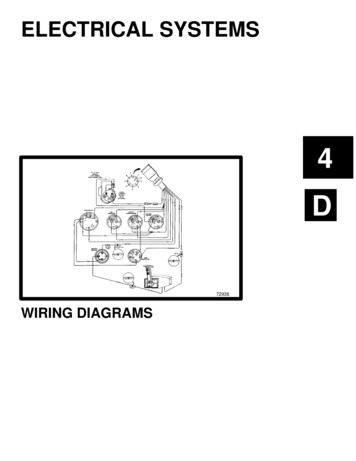
F RELAY LOCATIONS[Engine Compartment]Injector Driver(EDU)Skid Control ECUwith ActuatorEngine Room R/BEngine Room J/B20
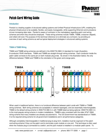
F[Instrument Panel]Engine ECUTransponder Key ECUTheft Warning ECUTurn Signal Flasher4WD Control ECUTransponder KeyAmplifierR/B No.3Transmission ControlECUA/C AmplifierShift LockControl ECUAirbag SensorAssembly CenterDriver Side J/B21
F RELAY LOCATIONS1: Engine Room R/B: Engine Room J/BEngine Compartment Left (See Page 20)(Inner Circuit : See Page 26)* 1:100A ALT (for High Current)* 2:80A GLOW (for High Current)* 3:50A BATT P/I (for High Current)* 4:30A AM2 (for High Current)* 5:40A MAIN (for High Current)* 6:40A ABS NO.1 (for High Current)* 7:40A FR HTR (for High Current)* 8:30A ABS NO.2 (for High Current)*1*2*3*4*6Unit C*5*7*81 15A 2FOGUnit A1 10A 2HORN17.5A 2ALT-S115A 2TURN-HAZ2 20A 1H-LP RH2 20A 1H-LP LH17.5A 2ECU-B115A 2RAD17.5A 2DOME130A 2DCCUnit D221 25A 2EFIUnit B
F(from Engine Room (from Engine RoomMain Wire)Main Wire)Unit A1313241B1C31Back View24423142Side ViewTop ViewUnit DSide View1E1F1(from Engine Wire)Wire Coler : B1G11A1(from Engine Room (from Engine RoomMain Wire)Main Wire)Wire Coler : BWire Coler : B1(from Engine RoomMain Wire)Wire Coler : W23
F RELAY LOCATIONS1: Engine Room R/B: Engine Room J/BUnit BEngine Compartment Left (See Page 20)(Inner Circuit : See Page 27)Top ViewBack View123412341I56785678(from Engine RoomMain Wire)12341J123456785678(from Engine RoomMain Wire)1H11(from Engine RoomMain Wire)Unit C153ST Relay2521324GLOW Relay
Memo25
F RELAY LOCATIONS[Engine Room R/B and Engine Room J/B Inner Circuit]Unit A1 1E1 1F100A ALT80A GLOW1 1G50A BATT P/I3 1B40A ABS NO.130A AM24 1B2 1B40A FR HTR40A MAIN3 1C1 1C30A ABS NO.22 1C1 1AUnit D1230A DCC1217.5A ECU-B12115A RAD1217.5A ALT-S121217.5A DOME115A TURN-HAZ12120A H-LP RH11220A H-LP LH261
FUnit B1 1IFOG Relay1 1H124 1I15A FOG3 1I2 1I5 1I12HORN Relay8 1I10A HORN7 1I6 1I1 1JMAIN Relay124 1J25A EFI3 1J2 1J5 1JEDU Relay8 1J7 1J6 1J27
F RELAY LOCATIONS: Driver Side J/BInstrument Panel Brace RH (See Page 21)Yellow12345678629105431(from Instrument (from InstrumentPanel Wire)Panel Wire)2B2A216 5 4 372I6542C31 2 345 67 8 91011
This wiring diagram manual has been prepared to provide information on the electrical system of the HILUX. Applicable models: KUN15, 16, 25, 26 Series For service specifications and repair procedures of the above models other than those listed in this manual, refer to the following manuals; M