Transcription
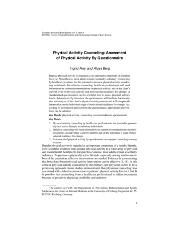
PHYSICAL REVIEW E 99, 012802 (2019)Universal scaling of polygonal desiccation crack patternsXiaolei Ma,* Janna Lowensohn, and Justin C. BurtonDepartment of Physics, Emory University, Atlanta, Georgia 30322, USA(Received 16 July 2018; revised manuscript received 29 November 2018; published 14 January 2019)Polygonal desiccation crack patterns are commonly observed in natural systems. Despite their quotidiannature, it is unclear whether similar crack patterns which span orders of magnitude in length scales share thesame underlying physics. In thin films, the characteristic length of polygonal cracks is known to monotonicallyincrease with the film thickness; however, existing theories that consider the mechanical, thermodynamic,hydrodynamic, and statistical properties of cracking often lead to contradictory predictions. Here we experimentally investigate polygonal cracks in drying suspensions of micron-sized particles by varying film thickness,boundary adhesion, packing fraction, and solvent. Although polygonal cracks were observed in most systemsabove a critical film thickness, in cornstarch-water mixtures, multiscale crack patterns were observed due totwo distinct desiccation mechanisms. Large-scale, primary polygons initially form due to capillary-inducedfilm shrinkage, whereas small-scale, secondary polygons appear later due to the deswelling of the hygroscopicparticles. In addition, we find that the characteristic area of the polygonal cracks, Ap , obeys a universal powerlaw, Ap αh4/3 , where h is the film thickness. By quantitatively linking α with the material properties duringcrack formation, we provide a robust framework for understanding multiscale polygonal crack patterns frommicroscopic to geologic scales.DOI: 10.1103/PhysRevE.99.012802I. INTRODUCTIONDesiccation crack patterns observed in natural systemsspan many orders of magnitude in size (Fig. 1) [1–6]. Amongthe large diversity of desiccation crack patterns, polygonalpatterns are the most common. Typical examples include thecomplex crack network in dried blood [7], craquelures in oldpaintings [8,9], T/Y-shaped cracks in dried mud [10], andpolygonal terrain cracks [11–13]. In particulate suspensions,the formation of desiccation cracks depends on the interplaybetween order and disorder in granular systems, as wellas mechanical instabilities initiated by local, nonequilibriuminteractions between the liquid, solid, and vapor phases [3,4].Nevertheless, a broad range of practical applications, suchas thin film coating, forensics, and controllable surface patterning, rely on knowledge of the physical processes thatdetermine crack patterns [14–18]. Despite numerous studieswhich focus on desiccation crack patterns in a diverse rangeof systems, a fundamental understanding of the characteristic length scales associated with polygonal crack patternsis lacking, and it is not clear if the observed patterns inboth microscopic and geologic crack patterns share the sameunderlying mechanisms.In the laboratory, drying particulate suspensions, bothBrownian and non-Brownian, are model systems for replicating and understanding desiccation cracks in nature. Fora crack to form in any material, the mechanical potentialenergy released during fracture must exceed the energeticcost of creating new surfaces [19]. In homogeneous, isotropic,elastic solids, the dynamics of fracturing have been 012802(12)characterized with exquisite detail [20–24]. However, the dynamics of drying-induced cracks are complicated by the lackof material homogeneity and a nonlinear relationship betweenstress and strain [3,25–31]. This complexity is enhanced bythe multiphase nature of the material: liquid menisci betweenparticles generate heterogeneous shrinkage through capillarypressure and excess liquid-vapor surface area in the bulkof the material [32–36]. As a consequence, in addition topolygonal cracks, a large variety of cracks patterns have beenreported in dried suspensions [8,30,37–52]. The variability inobserved patterns depends on numerous factors such as filmgeometry [40,53], particle mechanics [54], liquid additives[55,56], preparation history [57,58], solvent volatility [59,60],and external fields [61,62].Despite this broad range of crack patterns, we know surprisingly little about what controls the size and hierarchyof commonly observed polygonal cracks, which are visibleon both the micro- and macroscales. As shown in Fig. 1, adetailed understanding of desiccation crack patterns can leadto more accurate interpretations of planetary geomorphology,where data are limited to satellite-based imaging [12,13].Thus far, laboratory experiments and numerical models haveproduced contradictory results as to the mechanism and dependence of the crack spacing on desiccation conditions. Forexample, for regularly spaced cracks produced by directionaldrying, the relationship between the crack spacing, λ, andmaterial thickness, h, is a power law, λ hβ . Experimentally,numerous groups have reported β 1 [37,63,64], and varioustheoretical predictions give 2/3 β 1 [65,66]. For polygonal patterns, one may expect Ap λ2 h2β . Groisman andKaplan [67] reported Ap h2 in desiccated suspensions ofcoffee grinds, although only over a fourfold increase in h.Other experimental [68] and numerical [69,70] studies have012802-1 2019 American Physical Society
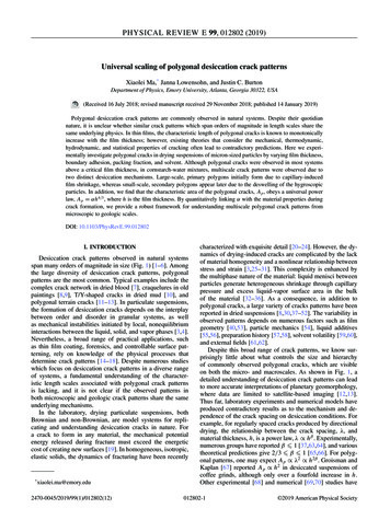
XIAOLEI MA, JANNA LOWENSOHN, AND JUSTIN C. BURTON(a)these cracks are due to two distinct desiccation mechanisms.Primary cracks form first due to capillary-induced shrinkageof the material. Secondary cracks form much later and are dueto deswelling of the hygroscopic cornstarch particles. Takentogether, these results provide a quantitative pathway forinterpreting multiscale polygonal desiccation crack patternsobserved in diverse systems, from microscale colloidal filmsto terrestrial and extraterrestrial planetary surfaces.(b)2 cmPHYSICAL REVIEW E 99, 012802 (2019)50 mII. EXPERIMENTFIG. 1. Multiscale polygonal crack patterns. (a) Crack patterns by drying cornstarch-water suspensions in a Petri dish.(b) Polygonal terrain in an ancient dried lake be on Mars (HiRISE:PSP 007372 2475, image courtesy of NASA/JPL/University ofArizona).reported similar scalings. Most recently, Flores [71] showedthat Ap h4/3 using a model based solely on a balance of theaverage stress and surface energy released during cracking.Yet despite this history of investigation, there has been nosystematic experimental study of the film’s thickness andmechanics on the size of polygonal crack patterns.The pattern morphology of polygonal cracks is also ofinterest since it reveals information about the formation andhistory of the cracking process [3]. For example, the distribution of angles at crack junctions [67,68,72] and statisticalanalysis of the correlation length in crack patterns [73] arecommonly quantified from images of the surface. Repeatedwetting and drying of the material can lead to more “Y”shaped junctions rather than “T”-shaped junctions [10,11].For some commonly used desiccation suspensions such ascornstarch-water mixtures, crack patterns with two distinctlength scales can be identified, as shown in Fig. 1(a). Forthick samples, the smaller polygons grow into the material,resembling columnar jointing patterns often found in nature[72,74–78]. These smaller polygons are also known to coarsenwith depth in the material [79]. Hierarchical patterns have alsobeen observed in the cracking glaze of ceramics [47,48]. Itis not yet apparent why some materials display hierarchicalcrack patterns and some do not.Here we present experimental evidence which resolvesmany of these important, outstanding questions. Our experiments involve analysis of desiccated crack patterns in variousgranular materials, such as cornstarch and CaCO3 , suspendedin different volatile liquids: water, isopropanol (IPA), andsilicone oil. We use both very thin, quasi-two-dimensionalchambers, as well as open Petri dishes to dry the samples.For all observed crack patterns, we find that the characteristic polygonal area is consistent with Ap αh4/3 overmore than three orders of magnitude in h, in agreement witha recent theoretical prediction [71] based on a balance ofstress and surface energy for crack formation. This scalingis independent of the shape of the polygons, which variesconsiderably depending on the material-liquid combination.By characterizing the modulus of the desiccated suspension,we are also able to quantitatively predict the prefactor α. Forall material-liquid combinations, we observe only multiscalecrack patterns in cornstarch-water mixtures. We show thatWe used commercial, polydisperse cornstarch particlesfrom ARGO. The average radius, R, of the particles is 5 μm. We also used CaCO3 particles from OnlineScienceMall with R 1 μm and, for some experiments, glass beadswith R 5 μm from Miscrospheres-Nanospheres. Particlesizes were measured using optical microscopy. Different fluids such as deionized water, low-viscosity silicone oil (0.65cSt, ClearCo), and 99.9% IPA were used as solvents to prepareparticulate suspensions. For samples thicker than h 1 mm,we dried suspensions in polystyrene Petri dishes of diameters14 cm and 8.5 cm. Glass microscope slides were used tobuild thin, quasi-two-dimensional chambers as discussed inSec. III E. For the thin chambers, the tunable thickness, h, wasset by vinyl spacers cut from a sheet. Once the vinyl spacerswere placed on the edges, a sample of suspension was placedon the microscope slide, and the sample was compressed bya second glass slide and secured mechanically before gluingwith optical epoxy. Similar setups have been used by previousauthors [32,37,38,80]. However, one important distinction inour experiments is that due to the relatively slow evaporationin this system, evaporation occurs nearly isotropically aroundthe perimeter of the sample, so drying is not unidirectional.We used a conventional bright-field microscope to imagecrack patterns in the thin chambers and a USB 3.0 digitalvideo camera (Point Grey) connected to a macrolens to imagethe crack formation during drying of particulate suspensionsin Petri dishes from above. Recorded images were analyzedusing NIH ImageJ software to obtain the area of polygonalcracks and thickness of the dried films. An electronic balance(Omega) was used to monitor the instantaneous mass ofsuspensions during drying. All experiments were performed atroom temperature (20 C) with uncontrolled relative humidityof 60%. Modulus measurements were obtained by slowlypressing a stainless steel ball of diameter 1.9 cm into thematerial using a rheometer (TA Instruments AR2000) andrecording the applied normal force.III. RESULTS AND DISCUSSIONA. Multiscale cracks in cornstarch-water suspensionsWe prepared cornstarch-water suspensions and dried thesamples in Petri dishes. We varied the thickness of the filmsby controlling the initial volume of the suspensions. Abovea critical thickness, hc , as will discussed in Sec. III B, weobserved two distinct crack patterns that appeared at different stages of desiccation. Figure 2 shows the formation ofthese multiscale cracks during drying of a cornstarch-watersuspension with φi 40%. As shown in Fig. 2(a), dryingoccurs at the air-water interface. The primary cracks (blue012802-2
UNIVERSAL SCALING OF POLYGONAL DESICCATION PHYSICAL REVIEW E 99, 012802 (2019)FIG. 2. (a) Experimental setup for drying cornstarch-water suspensions in Petri dishes where drying occurs at the top interface as indicatedby the red arrows. Formation of multiscale crack patterns during drying of a cornstarch suspension (φi 40%) in a Petri dish: (b) Image of theinitial suspension (t 0), (c) the primary cracks appear (t 10.5 h), (d) the number of primary cracks increases (t 11 h), (e) the numberof primary cracks stops growing (t 22 h), (f) secondary cracks appear (t 24 h), (g) the number of secondary cracks increases (t 29 h),(h) the number of secondary cracks stops increasing though drying still proceeds (t 42.5 h), and (i) the final crack pattern (t 72 h). Theinset in (f) is a zoomed-in view of the section enclosed by the yellow box. Some of the images here have been enhanced for the best visualizationof crack patterns, and the scale bar applies to all images. The final dried film has a thickness of h 0.7 cm. A video (Video S1) showing thedetailed formation of the multiscale structures can be found in the Supplemental Material [81].polygons) first appear, then as drying proceeds, secondarycracks (red polygons) appear within the larger polygons. Afterthe suspension has dried for t 10.5 h, primary cracks firstappear [Fig. 2(c)], and the number of primary cracks increaseswith time [Fig. 2(d)]. At t 24 h, secondary cracks are visible[Fig. 2(f)]. When t 42.5 h, the number of secondary cracksstops increasing though drying still proceeds [Fig. 2(h)].Finally, the drying contributes to the widening of the existingcracks, as shown in Fig. 2(h). We note that the primary crackspenetrate completely through the sample when they form,whereas the secondary cracks grow more slowly, and theirvisibility increases with time.As reported by previous authors [69,72,82], the primarycracks are a result of film shrinkage induced by the Laplacepressure on the scale of the particle size. As the water evaporates, menisci form between individual particles of radiusR 5 μm. Thus the average pressure is reduced in thesuspension by γ /R 15 kPa, where γ 72 mN/m is thesurface tension of water. Since the suspension is partiallyadhered to the bottom surface of the Petri dish, the cracks formalmost uniformly over the sample. Without this adhesion, thesuspension undergoes isotropic shrinkage, and the number ofprimary cracks is reduced [67]. Figure S1 [81] shows theeffects of different substrate boundary modifications on theprimary crack patterns in cornstarch-water suspensions [81].The secondary cracks are generally unaffected by the choiceof boundary condition, and the origin of secondary cracks willbe discussed in Sec. III C.B. Critical condition for primary cracksThe appearance of primary cracks for thicker samples ofcornstarch and water suspensions, as shown in Fig. 2, can beunderstood in terms of a well-known theory for the initiationof cracks in colloidal thin films [33,34]. The theory assumesa no-slip boundary condition between the bottom boundaryof the film and the substrate and predicts a relationship between the critical film thickness and stress when crack shouldappear: 2/3 GMφR 1/32Rσc R 0.1877,(1)2γhc2γwhere the definitions of the parameters in Eq. (1) are listed inTable I. Although the particle radius ultimately cancels from012802-3
XIAOLEI MA, JANNA LOWENSOHN, AND JUSTIN C. BURTONPHYSICAL REVIEW E 99, 012802 (2019)TABLE I. Physical properties of the parameters in Eq. (1).SymbolMeaningGParticle shear modulusRParticle radiusγSurface tensionMφhcσcCoordination numberRandom close packingCritical thicknessCritical stressValue4 GPa (cornstarch)32 GPa (CaCO3 )5 μm (cornstarch)1 μm (CaCO3 )72 mN/m (water)23 mN/m (IPA)16 mN/m (silicone oil)50.67Eq. (1), it is included here so that each term is dimensionless,as in Ref. [34]. We have included typical values for theshear modulus of both cornstarch and CaCO3 taken from theliterature [83], assuming a crystalline form of CaCO3 and aPoisson’s ratio of 0.5 for cornstarch. The same values of φand M were used for all calculations.Taking the typical values of the suspensions of cornstarchwater and CaCO3 -water used in the experiment (seeTable I), we can calculate the critical thickness for cracking.Since the stress driving the primary cracks is due to capillary pressure [63], we can assume that σc γ /R. Solvingfor hc , we obtain hc 1500 μm for cornstarch and hc 400 μm for CaCO3 . In order to examine whether Eq. (1)accurately predicts the critical film thickness for cracking,we dried both thin films of cornstarch-water and CaCO3 water suspensions in Petri dishes (Fig. S2). The critical filmthickness for cornstarch-water suspensions was measured tobe hc 1180 μm, whereas for CaCO3 -water suspensions,hc 550 μm. Both the critical film thicknesses we observedshow good agreement with the predictions by Eq. (1), thoughslightly different from the predicted values. However, Eq. (1)fails to explain the origin of secondary cracks in driedcornstarch-water suspensions. For the secondary cracks, thereis no critical film thickness, and the cracks are visible insamples that are only a few particles thick, as will be discussedin Sec. III E, suggesting that the stress is not solely due tocapillary pressure, as described in Ref. [63].C. Cornstarch particle deswelling drives secondary cracksMultiscale crack patterns in dried cornstarch-watersuspensions have been reported previously [47,48,72]. Thesecondary cracks in cornstarch-water suspensions have beenused as a model system to investigate the formation ofgeophysical columnar joints [6,74–78,84]. However, to thebest of our knowledge, the origin of the different types ofcracks is not well understood. It has been suggested that thesmall-scale cracks are driven by the spatial nonuniformity ofthe local shrinkage of the film [72,82], which has never beenconfirmed. More recently, Goehring [77] showed that thestrong separation between two distinct drying regimes dominated by liquid and vapor transport in the particle networkcould influence the formation of small-scale crack patternsFIG. 3. Deswelling of a large, individual cornstarch particle fromthe wet state (a) to the fully dry state (b). The lengths indicated in theimages are l0 27 μm and l1 24 μm. (c) Normalized evaporationrate of suspensions of cornstarch-water, -IPA and -silicone oil, andCaCO3 -water and -silicone oil. The symbols are defined as follows:ml (t ) is the instantaneous mass of the liquid in the prepared suspension, ml0 is the initial mass of the liquid, and m/ t is the initialevaporation rate of the liquid at t 0.in cornstarch-water suspensions, yet similar physics shouldapply in other particle networks where small-scale cracks arenot observed. Consequently, the underlying mechanism forthe formation of multiscale crack patterns remains unclear.One of the main results of this work is that distinctpolygonal crack patterns are due to distinct shrinkagemechanisms. The initial evaporation of the suspending liquidcreates capillary stress at the interface, which shrinks thesample and induces stresses sufficient for cracking (primarycracks). For cornstarch in water, the secondary cracks aredriven by a second shrinkage mechanism: the deswellingof the particles. We observed strong deswelling by dryingswollen cornstarch particles dispersed in dilute suspensions,and the average deswelling ratio was 5%–10%, as shown inFigs. 3(a) and 3(b).In order to examine whether particle deswelling is uniquefor cornstarch-water suspensions, we prepared suspensionsof cornstarch-water, -IPA, and -silicone oil and suspensionsof CaCO3 -water and -silicone oil and compared their dryingkinetics. We used an electronic balance to record the instantaneous mass of the prepared suspensions during drying, andthe results are shown in Fig. 3(c). The instantaneous massof the liquid, ml (t ), is normalized by the initial mass of theliquid, ml0 (vertical axis), and the drying time, t, is normalizedby the initial evaporation rate of the liquid, ml0 /( m/ t )(horizontal axis). It can be easily seen in Fig. 3(c) that thenormalized drying dynamics of all of the suspensions followthe same curve, except for cornstarch and water. The dryingdynamics are much slower at late times for cornstarch inwater, and the sample takes more than twice as long to012802-4
UNIVERSAL SCALING OF POLYGONAL DESICCATION PHYSICAL REVIEW E 99, 012802 (2019)increasing film thickness(a)5 cm(b)5 cm(c)5 cm(d)5 cmFIG. 4. Multiscale crack patterns observed in dried films of cornstarch and CaCO3 particles suspended in different fluids. Panel (a) showsimages of polygonal crack patterns in dried film of cornstarch in water with film thicknesses of 2, 7, 10, and 20 mm, from left to right,respectively. Panels (b), (c), and (d) show dried crack patterns of films of CaCO3 suspended in water, silicone oil, and IPA, respectively. In(b) the film thicknesses from left to right are 1.5, 2, 3, 5.5 mm; in (c) from left to right are 2.5, 4, 7.5, 9 mm; and in (d) from left to right are3.1, 5, 5.5, 9.5 mm.dry. This discrepancy suggests that the cornstarch particlesare deswelling in the later drying stage, so that evaporationdepends on diffusion of water out of the individual particles.Finally, the point where the drying rate of the cornstarch-watersuspensions start to deviate from the other four suspensionsis exactly when small-scale, secondary cracks show up duringdrying cornstarch-water suspensions in Petri dishes (t 24 h;see Fig. 2), indicating that the secondary cracks are driven bydeswelling-induced shrinkage.D. Primary cracks in different particle suspensionsAbove the critical thickness, we explored primary crackpatterns in various suspensions. We dried suspensions ofcornstarch and CaCO3 in water, silicone oil, and IPA inPetri dishes. We varied the initial volumes of the suspensionsin order to obtain different film thicknesses and polygonareas. Figure 4(a) shows the multiscale cracks observed indried cornstarch-water films, for different film thicknesses.For primary polygonal cracks, the average polygon area increases with thickness, whereas for secondary cracks, theaverage polygon area initially increases with film thicknessand then saturates for large h. For CaCO3 -water suspensions[Fig. 4(b)], the polygonal pattern is not isotropic, and hasa preferred direction. This anisotropy is well known and islikely due to particle chain formation induced by drying [85].For CaCO3 particles in both silicone oil and IPA [Figs. 4(c)and 4(d)], the cracks are distinctly different than those012802-5
XIAOLEI MA, JANNA LOWENSOHN, AND JUSTIN C. BURTON(a)PHYSICAL REVIEW E 99, 012802 (2019)(b)2 cmFIG. 5. Fully desiccated suspensions of cornstarch-IPA (a) andcornstarch-silicone oil (b). The two suspensions have the same initialvolume (124 ml) and the same initial volume fraction (φi 40%).The film thicknesses of the samples in (a) and (b) are 6 mm.The images are enhanced for better visualizations, and the scale barapplies to both images.observed in water; nevertheless, the characteristic size of thepolygons increase with thickness. This dependence will bediscussed in detail in Sec. III F.Although the liquids used in our experiments have differentsurface tensions and vapor pressures, we suspect that someof the differences in patterns are mostly due to particle-liquidinteractions and surface energies. For example, we have testedthe packing ability of various particle-liquid combinations(Figs. S3 and S4 [81]) and found significant differencesbetween the same particles in different solvents. The ultimatepacking fraction obtained after desiccation can potentiallyaffect the maximum strain attainable upon drying, the modulus and tensile strength of the sample, the adhesion to theunderlying substrate, and the visibility of the cracks. Forexample, after centrifuging prepared suspensions, we foundthat cornstarch particles pack significantly more densely (φ 0.51) in IPA than either water (φ 0.45) or silicone oil (φ 0.43), as shown in Fig. S3 [81]. In addition, both cornstarchand CaCO3 pack more loosely than spherical glass beads inwater (Fig. S4).We also observed a stark contrast in the crack patterns forcornstarch in both IPA and silicone oil as shown in Fig. 5. ForIPA suspensions, we observed only very fine surface cracks inthick samples (h 1 cm), which did not penetrate more than 1 mm into the desiccated material [Fig. 5(a)]. We suspectthat this is due to high packing density of cornstarch in IPA(Fig. S3 [81]), so that only the surface layer could obtainsufficient strain to crack upon desiccation. Suspensions ofcornstarch in silicone oil did not display any visible cracks formost thicknesses used in our experiments [Fig. 5(b)] and onlysmall cracks for very thick samples (h 2 cm). Even afterfull desiccation, the surface of these films looked like smoothpaste [Fig. 5(b)], suggesting that the particles retained somesort of sticky interactions, possibly due to residual siliconeoil adhered to the surface. Even weak, attractive interactionsare expected to have a significant effect on granular packingsand their mechanical properties for large system sizes [86].This hypothesis is consistent with the low packing density ofcornstarch in silicone oil (Fig. S3 [81]), suggesting that theparticles may have a strong affinity for the silicone oil.E. Cornstarch-water suspensions in thin chambersThe small-scale secondary cracks observed in Fig. 2(i) area unique feature of cornstarch-water suspensions and did notFIG. 6. (a) Experimental setup for drying cornstarch-water suspensions in quasi-two-dimensional chambers with thickness h.(b) The polygonal cracks in the final dried film are indicated by thered polygons. The dashed blue line represents the profile of the initialsuspension, and polygonal cracks (red) appear after the shrinkageof the initial suspension (blue arrows). Images in (c), (d), and (e)show the drying stages: (c) the initial suspension in the thin chamber,(d) the percolation of dried regions, which appear darker in colorsince they scatter more light, and (e) the final polygonal crackpatterns in the dried film. The scale bar applies to all of the threeimages.show evidence of a critical thickness (hc ), in contrast to primary cracks. In order to explore the thickness dependence ofthe secondary cracks, we prepared cornstarch-water suspensions with different initial volume fractions, φi , and then deposited the suspensions into the thin, quasi-two-dimensionalchambers, as shown in Figs. 6(a) and 6(b). We observed twodrying stages: initially a compaction front invades throughout the film; then a second drying stage “percolates” throughout the film with a characteristic branching pattern, leadingto the formation of liquid, capillary bridges between particles.Finally, the liquid bridges dried up followed by the formationof polygonal cracks after several days [see Figs. 6(c) and6(e)]. Videos showing the drying dynamics of cornstarchsuspensions in thin chambers with h 750 μm (Video S2)and 10 μm (Video S3) can be found in the SupplementalMaterial [81].Figure 7 shows images of the polygonal cracks observed inthe dried films of a cornstarch-water suspension (φi 26%)in chambers with increasing h. Note here the thickness ofthe chamber is safely taken as the thickness of the dried filmsince the final dried film was attached to the top and bottomsurfaces of the chambers, as shrinkage mostly occurred in theplane [Fig. 6(b)]. In very thin chambers (h R), “dendritic”fracture patterns are observed, as shown in Figs. 7(a) and7(b). Since the thickness of the chamber is comparable tothe particle size, these patterns were sensitive to the flow ofthe suspending liquid as evaporation occurred. As h exceedsa critical value, the sensitivity to flow ceased, and regular,polygonal cracks appeared, as shown in Figs. 7(c)–7(j). Thistrend holds true for all values of φi used in the experiments.It should be noted here that we also prepared suspensionsof glass beads and CaCO3 particles in thin chambers withwater; however, no cracks appear during drying of the suspensions in these chambers. This supports the hypothesis thatthe secondary cracks are due to a distinct drying mechanisminvolving deswelling of the hygroscopic cornstarch particles(Sec. III C).012802-6
UNIVERSAL SCALING OF POLYGONAL DESICCATION PHYSICAL REVIEW E 99, 012802 (2019)(a)(b)(c)(d)(e)(f)(g)(h)(i)(j)1 mmFIG. 7. Polygonal crack patterns of fully desiccated cornstarch-water suspensions in thin chambers with initial particle volume fractionφi 26%. Panels (a) to (h) represent the film thicknesses of 10, 25, 50, 100, 250, 400, 500, 600, 750, and 1000 μm, respectively. The scalebar applies to all images.F. Universal scaling of multiscale polygonal cracksFigures 4 and 7 show that the characteristic size of allobserved polygonal cracks, in both Petri dishes and thinchambers, increases with h. Although there are many waysto characterize the polygonal patterns, such as the averagenumber of edges, or the aspect ratio, we simply measuredthe average area Ap of the polygonal cracks. The results areshown in Fig. 8. The solid symbols represent cornstarch-watersuspensions desiccated in thin chambers. The data were nearlyindependent of the initial volume fraction deposited in thechamber (Fig. S5 [81]). The open symbols represent polygonsobserved in Petri dishes. More specifically, the open bluecircles represent the secondary cracks in dried cornstarchwater suspensions in Petri dishes, which overlap with thedata from the thin chambers. For very thick suspensions ofcornstarch and water, the area of the small-scale, secondarypolygons saturated and did not increase further. As we willshow in Sec. III G, the deswelling of the particles proceedsas a drying front that penetrates diffusively into the material.Thus, the effective thickness associated with the crack formation depends on the diffusion of water vapor from the film.As mentioned previously, numerous authors have investigated the thickness dependence of the characteristiccrack spacing or polygon area in desiccated suspensions[37,63,65–68]. However, for polygonal crack networks, mostof these studies cover a very limited range in thicknesses,so that a comprehensive picture of the thickness dependenceof polygonal cracks is lacking. Although there is significantvariation in the data from any single set of experiments, takentogether, our results in Fig. 8 strongly suggestAp αh4/3(2)over a wide range of thickness, for different types of polygon
material using a rheometer (TA Instruments AR2000) and recording the applied normal force. III. RESULTS AND DISCUSSION A. Multiscale cracks in cornstarch-water suspensions We prepared cornstarch-water suspensions and dried the samples in Petri dishes. We varied the thickness of the films by controlling the initial volume of the suspensions. Above