Transcription
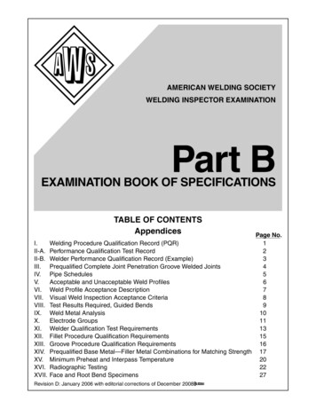
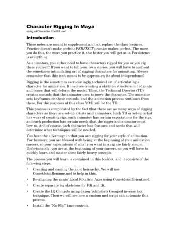
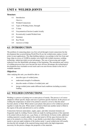
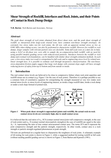
Computational Design of Twisty Joints and PuzzlesTimothy SunChangxi ZhengColumbia University Figure 1: Twisty Armadillo. (left) A twisty puzzle in the shape of an ARMADILLO whose rotation axes are placed along a triangular prism.(right) The output of our algorithm was fabricated, assembled, and scrambled into contorted poses. The different parts of the model, such asthe arms and legs, were deformed so that they do not collide with one other regardless of the configuration of the puzzle.Abstract1 IntroductionWe present the first computational method that allows ordinaryusers to create complex twisty joints and puzzles inspired bythe Rubik’s Cube mechanism. Given a user-supplied 3D modeland a small subset of rotation axes, our method automaticallyadjusts those rotation axes and adds others to construct a “nonblocking” twisty joint in the shape of the 3D model. Our methodoutputs the shapes of pieces which can be directly 3D printedand assembled into an interlocking puzzle. We develop a grouptheoretic approach to representing a wide class of twisty puzzlesby establishing a connection between non-blocking twisty jointsand the finite subgroups of the rotation group SO(3). The theoretical foundation enables us to build an efficient system forautomatically completing the set of rotation axes and fast collision detection between pieces. We also generalize the Rubik’sCube mechanism to a large family of twisty puzzles.Perhaps the most familiar example of a twisty joint is Rubik’sCube (Figure 2(a)), a 3D puzzle composed of 26 separate piecesattached to a core with six rotation axes, each of which canbe rotated independently. Rubik’s Cube and its variants, whichare known as twisty puzzles, are enormously popular around theworld: there are hundreds of “speedcubing” competitions for solving these puzzles every year, and new puzzle designs are beingmass-produced for those seeking new challenges (Figure 2(b)).Beyond their recreational popularity, twisty joints that share similar mechanics with Rubik’s Cube have found applications in manyareas, including mechanical joints for robotics [Ding et al. 2011]and omnidirectional security cameras [Khoudary 2000].CR Categories: I.3.5 [Computer Graphics]: Computational Geometry and Object Modeling—Geometric algorithms, languages,and systemsKeywords: Computational design, 3D fabrication, twisty puzzles, Rubik’s Cube, group theory, interlockingLinks: DLPDFWEBVIDEOe-mail: {tim, cxz}@cs.columbia.eduThe elegant and ingenious design of Rubik’s Cube addresses twoseemingly conflicting mechanical requirements. On one hand,it needs to be rotatable around different axes. Every rotationpermutes the puzzle’s pieces, which need to be aligned so thatthey can be rotated around other axes. On the other hand, allthe pieces are interlocked such that they never fall apart in anyconfiguration. Both goals are realized through precisely alignedrotation axes (Figure 3(a)) and the special shapes of the pieces,each with a hidden internal structure that interlocks with otherpieces (Figure 3(b)). Designing new puzzles and joints is a sophisticated task, requiring expert knowledge in twisty puzzledesign and often many iterations of trial and error. For example, even with CAD software, a user needs to manually checkthe internal mechanism for tiny undesired parts that result frommisaligned cutting surfaces.(a)(b)Figure 2: Twisty puzzles. Rubik’s Cube (a) and its variants (b).
In this paper, we propose a computational approach that enablesa non-expert user to easily design new and customized twistyjoints and puzzles. We model the structure of a twisty puzzlefrom an algebraic point of view. The cornerstone of our foundation is a connection between the rotation axis assignment fortwisty puzzles and the finite subgroups of the 3D rotation groupSO(3). Using this relationship, our method can take an arbitraryset of candidate rotation axes and automatically generate a similar set of axes that yields a workable twisty joint. Our interactiveand semi-automatic generation process in essence amounts toaligning finite symmetry groups to any set of axes (§5). The useronly has to specify a small set of rotation axes and the algorithmautomatically adds other cuts and produces fabricable 3D modelsof the resulting puzzle.We allow the twisty puzzle to have complex and user-customizedshapes (Figure 1), in contrast to the traditional twisty puzzleswhich are mainly symmetric and convex (Figure 2). To incorporate irregular shapes, an additional challenge arises: differentpieces may collide with one another while rotating around anaxis (see Figure 14(a)). We detect all these collisions and deform the shape to avoid collisions. With the help of our grouptheoretic foundation, we can enumerate all potential collisionsbetween pieces. We also reduce the 3D collision detection to a2D problem, significantly improving the runtime efficiency (§6).Finally, we develop an algorithm to automatically generate thegeometry of all the pieces, which, once assembled, interlock withone another and form a working puzzle (§7). Furthermore, weexploit the elasticity of the printing material and design a snapping mechanism to ease the assembly process, eliminating theneed for other hardware such as screws and springs (§7.3).Our core contribution is the first computationalapproach for interactively designing customized 3D twisty jointsand puzzles, featuring two major technical contributions:Contributions. We develop an algebraic treatment of twisty joints, and modelthe design of new puzzles using subgroups of the rotationgroup SO(3) (§4). We generalize the Rubik’s Cube mechanism to many othersets of rotation axes, and our designs can be 3D printed andassembled into interlocking puzzles (§7).2 Related WorkUBLRFD(a)(b)Figure 3: Rubik’s Cube. (a) The rotation axes of Rubik’s Cubeand (b) a peek at the internal mechanism. The pieces (inset) havelittle attachments and cavities that cause them to interlock.ing hinge joints between pieces. Rubik’s Cubes have been madein other shapes such as character’s heads [Scherphuis 2015], butthose shapes have been mostly convex or star-shaped.Transformable objects. One area of fabrication is concernedwith creating mechanical assemblies that can move, usually thosein the shapes of characters. Ceylan et al. [2013] created mechanical characters whose motions approximate motion-capturesequences. Concurrent work by Coros et al. [Coros et al. 2013;Thomaszewski et al. 2014] used a large set of linkages to generate a wider variety of trajectories for their mechanisms. Bächeret al. [2012] and Calì et al. [2012] fabricated articulated meshesby adding ball joints at key locations. Their models were printedin one piece, and the latter introduced friction to enable staticposing. However, all this previous work on transformable objects considers mechanisms where all the pieces are connectedby joints. In our setting, we need to consider that some piecesof twisty puzzles “float.” Pieces that are not connected to jointsare held in place by interlocking alone. The transformable objects we study have found applications in mechanical design androbotics [Khoudary 2000; Ding et al. 2011].One approach to designing fabricable objects is to make the process semi-automatic: with minimal userinteraction, the desired product is generated via an optimizationprocess. Mori et al. [2007] and Skouras et al. [2014] introducedinterfaces for designing plush toys and inflatable objects, respectively, by specifying the seams between patches of the surface.Interactive design has even been applied to garment [Umetaniet al. 2011] and furniture design [Umetani et al. 2012].Interactive design.With the advent of affordable rapid prototyping techniques such as 3D printing, one of the most popularhobbyist uses of rapid prototyping is puzzle design. The creationof such puzzles has been greatly enhanced by computationaltechniques. The design of polyomino puzzles on the surface ofarbitrary objects using quadrilateral meshing was introduced byLo et al. [2009]. Song et al. [2012] devised an algorithm forgenerating a large variety of interlocking puzzles made from voxelizations. Our approach resembles that of Xin et al. [2011], whoused constructive solid geometry algorithms for generalizing thesix-piece burr to arbitrary shapes.Mesh simplification is a common tool for fabricating an objectwith as few pieces as possible. Chen et al. [2013] introducea mesh simplification algorithm which generates large planarpieces suitable for fabrication, and Igarashi et al. [2012] generated beadwork by simplifying a model into a uniform hexdominant mesh. In the latter work, the user can interactivelyedit the shape of the simplified mesh. Our work also follows thesame philosophy of requiring minimal user interaction: the userspecifies a few initial rotation axes and our algorithm generatesa fabricable puzzle.In this paper, we focus on an entirely different class of puzzles.We might describe twisty puzzles as “dynamically interlocking”since pieces can move around while interlocked. Compared tothe aforementioned “statically interlocking” puzzles, the requirement that our pieces need to be movable after being assembledadds an extra challenge to the design process. Our puzzles relyon twisty joints to produce a large variety of puzzle piece combinations. Zhou et al. [2014] also introduced a type of transformable puzzle which “folds” an arbitrary object into a box us-Group theory and Rubik’s Cube. Both computer and humansolving techniques for Rubik’s Cube have benefited from treating Rubik’s Cube as an abstract group. Thistlethwaite’s algorithm [1981] restricts the state of the puzzle to smaller andsmaller subgroups until the puzzle is solved. Rokicki et al. [2010]showed that no position requires more than 20 moves by breaking up the problem into cosets of one of Thistlethwaite’s subgroups. Our application of group theory serves a different pur-3D puzzle design.
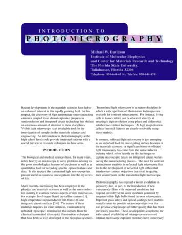
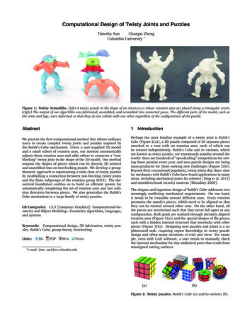
user-specifed cutssuggested cuts(section 5)cutting the puzzle(section 7.1)avoiding collisions(section 6)mechanism generation(section 7.2-7.3)Figure 4: Pipeline. Starting from simple user input in the form of planes, our algorithm finds a nearby set of non-blocking rotation axes(§5), slices up the puzzle according to those axes (§7.1), deforms the resulting pieces to avoid any external collisions (§6), and generates afabricable internal mechanism using those pieces (§7.2-7.3).pose: generalizing Rubik’s Cube to other puzzles. While thereexist variants of Rubik’s Cube that agree with the theory presented in this paper (such as the ones in Figure 2(b)), our maintheoretical result is new to our knowledge.core positionrotation axis3 Background and OverviewThe goal of this work is to automatically generate a 3D twistypuzzle given a 3D model and some approximate rotation axesspecified by the user. A special and simple case of the twisty puzzles that our method can generate is Rubik’s Cube. Throughoutthis paper, we constantly refer to it for illustration purposes, thuswe first introduce some of its terminology (§3.1) and then givean overview of our pipeline (§3.3).3.1 Basics of Rubik’s CubeRubik’s Cube has six possible “moves,” each corresponding toa rotation axis. These axes are referred to as U(p), D(own),F(ront), B(ack), L(eft), and R(ight) as in Figure 3(a). A movealong one rotation axis applies a 90 clockwise rotation to all thepieces on one side of a plane perpendicular to that rotation axis.We say that Rubik’s Cube is non-blocking because any sequenceof moves can be applied to the puzzle without the mechanismgetting stuck. An example of a puzzle with blocking is illustrated in Figure 10(b). Each rotation axis has a piece called thecenter which rotates in place, and internally, these centers areconnected to a core. The pieces with two and three stickers arecalled edges and corners, respectively. Figure 3(b) illustrates thedifferent kinds of pieces and the mechanism that holds all thepieces together.3.2 Jaap’s sphere.While it is natural to visualize Rubik’s Cube in its cubic geometry,in order to generalize to other twisty joints, we instead interpret the intrinsic structure of a puzzle using a sphere (Figure 5).This is sometimes called Jaap’s sphere [Scherphuis 2003]. Jaap’ssphere is wholly contained inside the puzzle, and we call thecenter of the sphere the core position of the puzzle. The sphereintersects with some cutting planes or cuts, each of which separates the sphere into two parts that can be independently rotated.In other words, each cutting plane defines a rotation axis whichis perpendicular to the plane and passes through the core position. In the context of our problem, by looking at a sphere, wecan more easily examine puzzles produced by arbitrary sets ofrotation axes, and we can produce a unified method for designing the internal mechanisms of puzzles produced by those axes(as detailed in §7).Figure 5: Cuts of a Twisty Puzzle. Some cuts of a Rubik’s Cube(left) and its Jaap’s sphere (middle), and the 2D projected view(right). Each cut can be described by a single perpendicular vectorinside the sphere.3.3 PipelineWe incorporate our pipeline (Figure 4) into an interface thattakes user-supplied 3D models and rotation axes, and displaysthe resulting puzzles interactively. Our pipeline generates 3Dmodels which can be directly fabricated and assembled (see thesupplemental video). Specifically, out pipeline consists of thefollowing steps:1. Positioning Jaap’s sphere. The pipeline is initialized by a3D model. We aim to make Jaap’s sphere as large as possible.Since all cutting planes have to pass through Jaap’s sphere,a larger sphere means a wider variety of cutting planes. Thealgorithm computes the optimal core position c by solving theoptimization problem c arg max min kp q kp int(S)q Swhere S denotes the surface of the 3D model and int(S) denotes its interior region. A solution to this optimization procedure is illustrated in Figure 6. Our implementation performssimulated annealing [Kirkpatrick et al. 1983] starting fromthe center of mass of the model. We then set the radius ofJaap’s sphere to be minq S kc qk.Figure 6: Fitting Jaap’s sphere inside the Stanford bunny with the optimal core position c. We make thesphere as large as possible inside theobject.2. Axis auto-completion (§5). Using the graphical interface,the user specifies cuts that pass through the 3D model andJaap’s sphere. These cuts define a subset of rotation axes,but they may generate a puzzle that blocks. Our algorithmperturbs the user-specified cuts and adds other rotation axesto produce a non-blocking puzzle. The good sets of cuts arederived using results on rotation groups (§4).
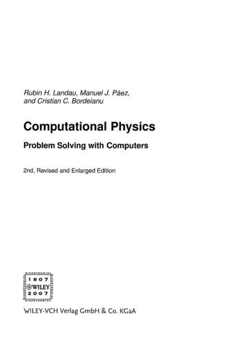
3. Resolving collisions (§6). The suggested cuts then separatethe provided 3D model into individual pieces. Inside Jaap’ssphere, these pieces can freely rotate around the axes. However, for complex shapes, the resulting pieces may collide withone another in certain positions of the puzzle. We enumerate all possible configurations of pairs of pieces by defininga group structure on the pieces. A 2D collision detection algorithm is introduced for this problem. Once collisions aredetected, they are resolved using standard Laplacian meshdeformation algorithms.4. Internal mechanism (§7). Finally, for every piece of thepuzzle, we create an interlocking internal mechanism whichrotates according to the rotation axes. The mechanism is ageneralization of the Rubik’s Cube mechanism; its generationuses only constructive solid geometry operations on simplegeometric primitives.4 TheoryIn this section, we operate on Jaap’s sphere, ignoring for now the3D model surrounding the sphere. We will consider the shapesof 3D models in §6 and §7. Without loss of generality, we assumethat the sphere has unit radius and is centered at the origin. Thegoal of this section is to develop a relationship between validsets of rotation axes and an algebraic result on rotations in R3and define an algebraic group structure on the positions of apuzzle. We refer to a Rubik’s Cube throughout for illustrating theconcepts, even though we consider a much wider class of twistyjoints and puzzles.corecenterFigure 8: Piece Types. (left) A corner piece of Rubik’s Cube isspecified by three cuts (or equivalently, three rotation axes). (right)A 2D illustration of the core and center pieces.pieces on the far halfspace by 2π/n clockwise about the axis v .The (unique) piece containing the origin is called the core, whichis often concealed by the other pieces. The pieces that lie on thefar side of exactly one rotation axis are called centers. Note thatevery center touches the core. For the purpose of designing theinternal mechanism in §7, we need a core and a center for eachrotation axis: having the centers affixed to the core is the basisof the interlocking design. By requiring that the length of therotation axis is positive (i.e., kvk2 6 0), we ensure that no planecuts through the origin, guaranteeing the existence of the corepiece. To make sure that each rotation axis ri has an associatedcenter piece, for every other rotation axis r j , i 6 j, v i is on thenear halfspace of r j , i.e. (v i v j ) · v j 0. On Rubik’s Cube, therotation axis passes through the center piece, but on the right ofFigure 9, the “center” piece of the green rotation axis is actuallyon the far side of two rotation axes.Figure 9: Because we needcore and center pieces forthe mechanism design, wedo not allow these typesof rotation axis configurations.4.1 Abstract Puzzle RepresentationA rotation axis r (v , n) is specified by a nonzero vector v whosenorm is strictly less than 1 and an integer n. The direction of vindicates the orientation of the rotation axis, and the length of vindicates where the sphere is cut (Figure 7). The cutting planeis the plane that passes through v and is perpendicular to v , i.e.the locus of points (p v) · v 0. Thus, in our presentation,we refer to v as a vector and as a plane interchangeably. Therotation axis can be turned by angles of 2π/n. For example, theaxes of Rubik’s Cube have n 4. Furthermore, we call the twohalfspacesr 0 {p (p v) · v 0} and r 1 {p (p v ) · v 0}the near and far sides or halfspaces of the rotation axis, respectively.cutting planefar sidenear siderotation axisFigure 7: A rotation axis and its cutting plane on a Jaap’ssphere. The cutting plane forms two halfspaces that we use todescribe pieces.A set of rotation axes partitions the sphere into pieces. A piecessp {r11 , . . . , rkk } is specified by the halfspaces which form it,where si , i 1, . . . , k is either 0 or 1, depending on which side ofthe axis ri the piece is on. For instance, a corner of a Rubik’s Cubeis specified by three far halfspaces, and an edge is composed oftwo far halfspaces and two near halfspaces (Figure 8). Turninga rotation axis r (v , n) by its angle 2π/n rotates each of the4.2 Non-Blocking PuzzlesOne crucial property of twisty joints and puzzles is that they arenon-blocking. An illustrative example of how to make a blockingpuzzle non-blocking is the “two-generator” Rubik’s Cube, whereonly two adjacent faces can turn. If we only cut the cube usingthe two rotation axes U and R (Figure 3(a) and Figure 10(a)), itis clear that this puzzle will lock—after turning R clockwise (Figure 10(b)), the U axis is blocked. To remove this blocking, we cancut along the U axis’s plane again (Figure 10(c)). Applying thisprocess repeatedly to our example will produce a non-blockingpuzzle.However, for most sets of rotation axes, this process never terminates and we will end up with an infinite number of pieces.Therefore, a physically meaningful puzzle needs to have carefullyarranged rotation axes such that the number of resulting piecesis finite. Our characterization of sets of rotation axes that arenon-blocking is based on finite subgroups of SO(3), the group ofrotations of the sphere. In particular, for each element of one ofthese subgroups, we make a cut perpendicular to that element’saxis of rotation. As a result, the number of resulting pieces isguaranteed to be finite. The justification of this connection between rotation axes and finite subgroups of SO(3) is detailed inAppendix A and is, to our knowledge, new. In fact, there is asuccinct characterization of the finite subgroups of SO(3):Theorem. [Thurston and Levy 1997] Any finite subgroup of SO(3) is isomorphic to a cyclic group, dihedral group, or a rotational symmetry group of a
UFlags:(p, R)(p, F)(p, U)F(a)(b)(c)(d)Figure 10: “Two-generator” Rubik’s Cube. Cutting a cube using only two rotation axes (a) will block after just one turn (b).Blocking can be resolved by cutting the puzzle further (c-d).(a)(b)Figure 12: Flags. (a) Each rotation axis applies a permutationon the pieces. (b) The flags of a corner of Rubik’s Cube. Flags canintuitively be thought of as different stickers of pieces.Platonic solid.We visualize these families of rotation axes using polyhedra (seeFigure 11)—when we refer to a rotation axis corresponding to afacet of a polyhedron, we mean the rotation axis that is parallelto its centroid. The sets of rotation axes correspond toFigure 13. However, in our user interface and examples, we onlyconsider the rotation axes of the finite rotation groups (recallFigure 11). Furthermore, we do not have a general classificationof all possible sets of rotation axes that have a well-defined puzzlegroup.1. the square faces and/or the n-gonal faces of the n-prism(cyclic, dihedral).2. the faces, edges, and/or vertices of the Platonic solids (tetrahedral, octahedral, icosahedral).As an example, Rubik’s Cube is an instance of the octahedralclass. Subsets of these (like the two-generator example) can beachieved by “fusing” centers to the core to block their motions.Because of the group-theoretic derivation of these sets of rotationaxes, we will refer to them simply as the finite rotation groups.Figure 13: A set of axes that does not come from a finite rotationgroup, but still can be described by a puzzle group. The rotationaxes are the faces of this “polyhedron” which consists of two hexagonal cycles of square faces. The centers do apply a permutation tothe two adjacent lune-shaped pieces.5 Auto-Completion of Rotation Axes(a)(b)(c)Figure 11: Examples of polyhedra which have finite symmetrygroups. These have octahedral, dihedral, and icosahedral symmetries, respectively, and we place rotation axes along the fixed pointsof a rotational symmetry.4.3 The Puzzle GroupA permutation τ : X X is a one-to-one correspondence of theelements of a set X . In the context of our problem, applyingmoves to Rubik’s Cube shuffles pieces around (Figure 12(a)), sothese moves can be expressed as permutations. However, thepermutation is not on the pieces, since pieces can have differentorientations. For example, a corner piece can be “twisted” in thecorrect position. We therefore define the flag (p, r ), which is apair of a piece p and one of its rotation axes r . The piece’s flagsencode the orientation. For example, each corner and edge of aRubik’s Cube has three and four flags, respectively (Figure 12(b)).The flags of a core piece and one of each center’s flags (i.e. theflag (p, r ) where r 1 p) stay fixed under the action of anyrotation axis, so we ignore them.Rotating the puzzle along a rotation axis applies a permutationon the flags. We refer the reader to Appendix B for details onhow to compute these permutations. Arbitrary compositions ofthese permutations form the puzzle group of the puzzle, whichdescribes all the possible states of the puzzle.Remark. The puzzle group defined here is general enough fordescribing other sets of rotation axes, such as the one shown inAs developed in §4.2, a non-blocking twisty puzzle is constructedby choosing rotation axes derived from a finite rotation group.To ease the user in specifying valid sets of rotation axes on anarbitrary shape, we provide an interface to allow the user tosketch a few planes that cut through the 3D model and the Jaap’ssphere inside (see the supplemental video). Every user-specifiedplane defines a rotation axis. Our algorithm then automaticallyadjusts these cuts and suggests other cuts to form a valid puzzle.In general, user-specified cuts will not be perfectly aligned withany of the Platonic solids or n-prisms. Instead, we take eachof the finite subgroups and rotate it to fit the user-specifiedrotation axes as closely as possible. There is an infinite number of dihedral groups Dq , so in practice we set a threshold byonly considering q 5. Suppose the user specifies n rotationaxes r1 , r2 , . . . , rn and we have a subgroup with m rotation axess1 , s2 , . . . , sm , where m n. For each pair of rotation axes ri andr j , we compute the angle θi j . Meanwhile, for all ordered subsets of size n of s1 , . . . , sm , we similarly compute angles θi′j andchoose the set which minimizesXkθi′j θi j k2 .1 i j nHere we can reduce the number of subsets by accounting forrotational symmetries. Let s1′ , . . . , sn′ denote the optimal orderedsubset of rotation axes drawn from a particular subgroup withthe axes s1 , s2 , . . . , sm . We wish to rotate these axes to align withuser-specified axes as closely as possible. To this end, we find arotation matrix R that minimizesnXi 1kri Rsi′ k2 .
(a)(b)Figure 14: Collisions of Puzzle Pieces. Even though a puzzleis non-blocking, pieces may collide with one another (a). Thesecollisions can occur when at least one of the pieces has overhang(b). If there is no overhang, then each piece is confined to anintersection of halfspaces, and these regions are all distinct fromone another.Figure 15: Collision Detection in 2D. We reduce the collisiondetection problem from 3D to 2D by projecting each mesh onto ahalfplane. The projection removes the angular component fromthe meshes, which is equivalent to rotating the halfplane about therotation axis and finding the intersection with the two meshes (seethe supplemental video).In graphics, this is known as shape matching [Müller et al. 2005;Rivers and James 2007] (and in other fields it is called the orthogonal Procrustes problem [Gower and Dijksterhuis 2004] andWahba’s problem [Wahba 1965]). The standard solution, as seenin [Müller et al. 2005], is to consider the following matrix andits polar decomposition:For each pair of pieces, we check if there exists some configuration of the puzzle, including during moves, where they collide.One case does not need to be checked because it can always beavoided: if two pieces collide only while applying two movessimultaneously (for example, manipulating two parallel rotationaxes), we can simply apply the two moves sequentially. As aresult, we only need to check cases where one piece is beingrotated while the other piece stays fixed.B nXri si′T RS,i 1We need to enumerate all the possible locationsand orientations these pieces can be in. In between moves, thereare a finite number of positions and orientations a piece can bein. Since the orientation of a piece is encoded by one of its flags,these positions constitute the orbit of the flag. For example, theorbit of a corner’s flag on Rubik’s Cube has 24 flags: three flagsfor each orientation of the eight corners.Orbits of flags.where S is a positive-semidefinite matrix and R is the desiredrotation matrix. Both matrices can be computed using the singular value decomposition [Golub and Van Loan 2012]. Finally,we apply R to all the rotation axes s1 , s2 , . . . , sm to obtain therotation axes (i.e., Rs1 , . . . , Rsm ) for puzzle generation. We scalethe vectors so that their lengths equal the average length of theuser-specified rotation axes.6 Avoiding CollisionsAfter completing the rotation axes based on user-specified cuts,we use the associated planes to cut the given 3D model intoindividual pieces (details in §7.1). Unfortunately, since we arecutting arbitrary geometries, pieces of the puzzle may collidewith one another after applying several turns (Figure 14(a)).Such collisions can be considered as another type of blocking.In this section, we first present an approach to detect all possible collisions without using any temporal collision detectiontechniques such as a direct simulation of puzzle rotations (§6.1).The 3D collision detection problems are reduced into 2D problems, drastically increasing the efficiency of our algorithm. Thesetwo simplifications allow us to check only a finite set of configurations, and symmetries reduce the number even further. Wethen resolve the collisions using simple Laplacian-based meshdeformations (§6.2).6.1 Collision DetectionA piece cut out from a 3D model is said to have overhang if partof the piece intersects one of its rotation axes, as in Figure 14(b).We observe that if two pieces are free of overhang, then it is impossible for them to ever collide, while the existence of overhangmay not necessarily lead to collisions. It suffices to check onlythe pairs where at least one of the pieces has overhang. One simple approach is to deform every piece until there is no overhangregardless of the actual collisions. While this can guarantee thereare no collisions, we often only need moderate deformations ornone at all.To compute the orbit of each flag, we create a graph where eachflag is a vertex. There is a directed edge from f to f ′ if there isa rotation axis r that brings f to f ′ (this information can beendetermined from the puzzle group). On the directed edge, westore a rotation corresponding to r . The connected componentcontaining a flag f is its orbit, and it can be found by a depth-firstsearch. The transformation from f to another flag f ′ in its orbitcan be computed by tracing the path of edges from f to f ′ in thedepth-first search tree and composing the resulting sequence ofrotations. By abuse of notation, we write the orbit of a flag ofpiece pi as O(pi ), because the orbits of different flags of a singlepiece are all isomorph
are known as twisty puzzles, are enormously popular around the world: solv-ing these puzzles every year, and new puzzle designs are being mass-produced for those seeking new challenges (Figure 2(b)). Beyond thei