Transcription
Character Rigging In Mayausing ekCharacter ToolKit.melIntroductionThese notes are meant to supplement and not replace the class lectures.Practice doesn’t make perfect; PERFECT practice makes perfect. The moreyou do this, the more you practice it, the better you will get at it. Persistenceis everything.As animators, you either need to have characters rigged for you or you rigthem yourself! If you want to tell your own stories, you will have to confrontthe sometimes intimidating art of rigging characters for animating. Alwaysremember that this isn’t meant to be oppressive; its about independence!Rigging is the sometimes excruciatingly technical art of articulating acharacter for animation. It involves creating a skeleton structure out of jointsand bones that will deform the model. Then, the Technical Director (TD)creates controls that the animator uses to move the character. The animatorsets keyframes on these controls, and the animation process continues fromthere. For the purposes of this class YOU will be the TD.This process is complicated by the fact that there are as many ways of riggingcharacters as there are set-up artists and animators. Each TD or set-up artisthas ways of creating rigs, each animator has certain expectations for the rigs,and each production has certain needs that the rigger and animator mustbow to. And of course, each character has features and needs that willdetermine what techniques will be needed.You have the advantage in that you are rigging for your style of animation.Furthermore, you are blessed with being at the beginning of your animationcareers, so your expectations of what you want in a rig are fairly simple.Unfortunately, you are at the beginning of your careers, so you will have toquickly learn and master some fairly heavy conceptsThe process you will learn is contained in this booklet, and it consists of thefollowing steps: Creating and naming the joint heirarchy. We will useCometJointRename.mel to help in this. Re-aligning the joints’ Local Rotation Axes using CometJointOrient.mel. Create separate leg skeletons for FK and IK. Create the IK Controls using Jason Schliefer’s Grouped inverse foottechnique. Then we will see how a custom mel script can automate thisprocess. Install the “No-Flip” knee controls.
Create FK Controls on each leg. Create a switch control to switch between the two control skeletons. Create StretchyIK back. Create FK controls for the stretchy back. Create separate control skeleton controls for the arm IK and FK. Create the FK controls for the collar, shoulder, elbow. Create forearm average control for the Forearm and Wrist. Create the IK Controls for the arm. Create the neck and head controls. Create eye controls if necessary. Create Follow control for the head. Create Follow controls to allow the IK legs and arms to follow the body orthe world. Group all controls appropriately for animation.Yes, this takes EXACTLY as long as it sounds! Which is why I, your soon tobe beloved instructor, have written ekCharacterToolKit for your use. ThisMel script provides a push button interface for using the many andvaried scripts designed to automate the rigging process. This documentwas originally 280 pages of which the first 140 pages was all aboutrigging the skeleton. It is now quite a bit shorter!Automation vs. CustomizationUnfortunately, to take advantage of this wonderful automation, there are acouple of things that you MUST do:Spelling and Capitalization: The power of naming in Maya is enormous!The ancients believed that if you knew someone’s name, you had powerover that person. In Maya, if you know the name of something, you canchange it through scripting. The scripts I have written rely HEAVILY onproper naming. Therefore you must name things EXACTLY as I require.Failure to do so will cause just about every one of my scripts to fail.The good news is that the scripts I have written by and large namethings for you, but there may come times when you will need to type orrename some things yourself.Orientation: As you will see, almost all the joints have their defaultrotations set a particular way. This default rotation is its Orientation.There are several ways to orient a skeletal joint; for consistency’s sake, Iwill insist on a certain way of doing things.To get you into the animation phase as quickly as possible throughautomating the set up process, we must sacrifice some ability to
customize your characters. That is part of the inevitable trade-off in thisprocess. To make it practical to set up multiple characters, you will notlearn to rig from scratch, you will learn to use the tools I have written.The good news is that they are powerful, flexible and will not limit you interms of your animation abilities.With this in mind, let’s begin to create the skeleton.The Maya System of Joints and BonesMaya joints are a type of deformer that are designed to transfer rotationalvalues to points on a model based on each joints influence on thosepoints. Joints are most often arranged in a hierarchy–meaning that onejoint is a child or farther down on the hierarchy than the parent.Each child of a parent exists in the local space of that parent. This meansthat the translate values of the child are listed as distances from theparent. This is important to understand where joints are concerned.Zeroing out a joint’s translate attributes will cause the joint to snap backto the location of the parent. The ultimate parent is the World space asdefined by the world origin at 0, 0, 0.The three joints shown below were created with the X axis pointing down thebone, the Y axis pointing up and the Z axis pointing forward in space.Knowing this is important to understanding what comes next.Pressing the W key, while LM clicking with the mouse will allow you tochange the space in which the translate tool will work. You have threechoices:World–Will move the joint (and any other object) in the World spacealong the World XYZ axes.Local–Will move the joint along the axes defined by the parent. Note themiddle image above: the x axis is point in the same direction as theparent.Object–Will move the joint along the joint’s own axis as defined by itsorientation.Joints also have Orientation which will effect the direction in which theypoint. For our purposes, we will always work with the X axis pointingdown the joint.Arbitrary Point #1–Work with the X axis pointing down the joint.It is possible to have differing orientations for different parts of
the body. You may one day decide that it is easier to have Ypointing up the spine joints and X pointing down the arm joints.However for learning purposes (and because many of the scriptswe will use to make these tasks easier expect the X axis to bepointing down the joint), it is much easier to learn with thisconsistent principle.Installing ekCharacterToolKit.melBefore we begin rigging, we must install ekCharacterToolKit.mel and all ofthe scripts that this UI script runs. To install all the scripts, do thefollowing:1.If you are in Maya, quit the program.2.Copy the folder ekCharacterToolKit Files to your desktop.3.In a Finder window, navigate to the following scripts Where User isthe name of the account you have. NOTE: it is crucial that you use thescripts folder in the 8.5 folder and NOT the scripts folder in the mayafolder. If you make this mistake, the scripts will not load at startup andyou will have to go back and move all these scripts to the right folder.4.Copy the following files to this scripts kMakeWeightDance.melFS faceCurves.melFS addInfluences.melThis should represent the entire contents of the folder.
5.Start Maya. When Maya starts it loads or “sources” all the .mel files inthe scripts folder.Creating and Naming the Joint HeirarchyOur example character is named “Oswaldo”. Open OswaldoGeo.mb to see himin all his glory.Let’s create the leg skeleton as follows.1.In the side view, hold down the command key and press both the LM andMM buttons. Zoom in to center on the leg.2.Press 4 to enter wireframe key. (Press Shift 4 to enter wireframe mode inall windows.3.Go to Skeleton Joint Tool .Press the Reset Tool button to set the tool the way we want it, then setboth the short and long bone radii to 1. This keeps the joints the samesize.
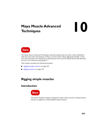
4. Draw a joint chainthat looks like the oneat left. Name thejoints as shown.Click Hold and dragto move them aroundbefore setting thenext joint.If you need to movethe joint you just setand have releasedthe mouse button,MM drag the jointinto position.If the joints are toolarge to placeproperly, go to theAnimationPreferences window,click on theKinematics categoryat left and change theJoint Size value. (.38shown here).Here we are using atwo knee jointconfiguration whichmakes weighting theknee a little easier.Arbitrary Point #2There MUST be a slight bend in the chain from the Hip to theAnkle. A completely straight chain will not bend with the IK.Also, you should be diligent in placing joints in the middle ofgeometry that will deform as seen in the knee and ankleareas. This is contrary to actual anatomy, but is crucial togetting smooth deformations.
Now lets get to the interface:In the command line (in the lower left corner of the interface) of the mainMaya window type:source ekCharacterToolKit.mel; ekCharacterToolKit;Then press the Enter or Return keysAt right is the ekCharacterToolKitinterface. It simply representsthe tools and commands we willuse in rigging our characters.While I have not tested it onquadraped characters, there isno real reason why it shouldwork.As with any custom tool–you willneed to learn how and when touse each command. There arecertain things that you MUSTdo for each command to work.Part of the purpose of thisdocument is to teach you how touse each one.These commands are listed in orderof use. Most often, you willcreate and name a jointhierarchy or skeleton first, sothe most useful tool for thatpurpose is listed first.Now that you have the leg and footjoints created and basicallynamed, we can speed things upwith the Comet Rename script.Press that button and
you will see the window at left.This tool renames objects andjoints. More importantly, it alsoadds prefixes and suffixes andsearches and replaces textstrings in object names.We will use it to add the characterprefix and the side suffix.We will do so as follows:1. Select the Hip joint by clicking on the top level joint or by pressing theup arrow key several times. The arrow keys let you navigate up anddown a hierarchy.2. Press the “Select Hierarchy” button at the bottom of the cometRenamewindow. This selects the entire joint hierarchy. Note how the jointschange color with the last joint in the hierarchy turning the colorgreen while all other joints are white. Noting the colors in theselection will help you determine what is selected first (white) andwhat is selected last (green).3. With all the joints selected, type “Osw ” in the Prefix: field.4. Click the Add Prefix button. Note how the names of the joints changein the Channel Box.5. Type “ L” in the Suffix: field and press Add Suffix. This appends theside suffix to the joint’s name.6. Click on the PerspOutlinerbutton in the toolbar.
7. In the now visible Outliner,shift-click on the next to theOsw Hip L joint to open thehierarchy. Now your Outlinerwindow should look like this.Clearly, CometRename can saveyou a lot of typing.When you create joints from one of the orthogonal planes (Front, Side,Top), you are making them on the XYZ plane that is perpendicular tothat window. For example, when you made the joint chain originally,you were creating the joints on the YX plane directly in the middle ofthe character. Let’s line this joint chain as follows:1. Select the Osw Hip L joint.2. Press and hold the space bar to bring up the Hotbox.3. Click and hold on Autodesk to bring up the view marking menue andgo to the front view.
4. Press the w key to invoke theTranslate tool.5. Drag the Osw Hip L joint toline up with the middle of theleft leg as shown at left.Arbitrary point #3:When modeling yourcharacters, it will behooveyou to model yourcharacters with legs parallelto the YX plane because thiswill make lining up your legjoints much easier. Makingcharacters that are bowlegged or pigeon-toed, whilepossible, are unnecessarilycomplicated at thebeginning of your characterdesign efforts.Next, we will mirror these joints asfollows:1.Go to Skeleton Mirror Joints Click YZ for the Mirror Across:option, choose Behavior for theMirror Function. Type “ L” forthe Search For: field and type“ R” for the Replace With: field.2.Click Mirror, and your jointswill mirror across the YZ planeand be suffixed with the Rdesignator.
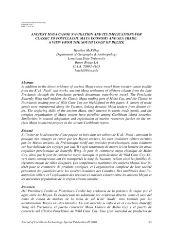
Creating The SpineThe Spine of any character is the most important set of joints in any rig. Aflexible, supple spine allows the animator to create interesting actionlines to his or her poses. This is the beginning of any superioranimation.In the images at left, you can see ananatomical drawing of the spinejuxtaposed with a preliminaryplacement of the spine with ourcharacter. This juxtapositionrevealsArbitrary Point #4: Unlike a“real” spine, you shouldplace the joints in themiddle of the character.This will aid thedeformation of the torsoand abdomen.Let’s create our spine as follows:1.Select Skeleton Joint Toolfrom the Skeleton menu.2.In the side view begin at thebottom and create a series ofjoints like you see at left. Try tocreate a spine of around 12joints. This will allowsuppleness while not being toodifficult to weight later on. Youcan click and drag to placejoints. You can also MM clickon the most previously placedjoint to move it into position.3.Press Return to accept thechain.I can almost guarantee you that your joint chain will not be perfect. Minenever is. So we will adjust joints within the chain as follows.
1.Select the joint you want tomove.2.Press the w key to invoke thetranslate tool.3.LM drag the joint and all itschildren into place.BUT WAIT! What if I want to movethe joint, but not the children?4.Before moving the joint, pressthe Home key on the keyboardto enter Move Pivot mode. Themovement cursor will change.5.Move the joint as needed. Thechildren will stay in place.Practice a little “digitalchiropractic” and align thespine as you see in the nextimage. Try to keep a smoothline to the spine hierarchy.Press the Home Key again to leaveMove Pivot mode.Now we will name the spine appropriately.
Renaming the SpineRename the Spine joints as showneither using cometRename orby manually renaming eachjoint.Manually rename the joint byclicking on the joint, thenchanging its name in theChannel Box (shown below) oroutlinerAdding the Neck and Head JointsWe will move a little faster when adding the Neck and Head joints1.Go to Skeleton Joint Tool.2.Click on the CSpine joint tobegin adding joints to thehierarchy.3.Add joints as shown at left.4.After placing the HeadTopjoint, press Return to accept thechain5.Rename each joint as shown.
Adding the Jaw and Mouth JointsThe Face/Jaw construction is very easy; we will not use many jointsbecause we will do facial poses using influence curves andblendshapes. Let’s create the Jaw Face joints as follows.1.Go to Skeleton Joint Tool.2.Click on the Head joint to beginadding joints.3.Create a chain as shown at left.Press return to accept thechain.4.Name the joints as indicated.NOTE! It is CRUCIAL that youspell and capitalize these jointsexactly as indicated.5.Deselect the chain by clickinganywhere in the background.6.Go to Skeleton Joint Tool.7.Click on the LowerJawBase joint to begin adding joints.8.Add a joint at the corner of the mouth. The easiest way to do this is toadd it from the side view and move it into position from the frontview. You do this by MM click-hold and dragging it in the front view.9.Name it “Mouth L”.10. Go to Skeleton Mirror Joint to create a mirrored copy calledMouth R.These joints will figure very prominently when we rig the facial curves.
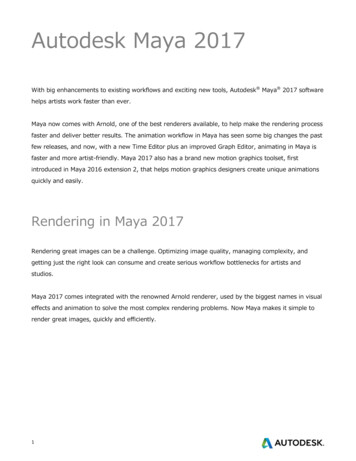
Creating the Arm JointsArbitrary Point #5: When modeling, create the arms of yourcharacters facing straight out from the body in what is calledthe crucifix pose. This allows you to place joints much moreeasily.Let’s place the arm joints as follows:1.Make sure you are in the front view. (Hold Spacebar, click onAutodesk in the middle of the Hotbox and choose Front).2.Go to Skeleton Joint Tool.3.Hold down the x key and place joints at the locations indicated. The xkey invokes Maya’s Grid Snap feature which places items on each gridlocation. You are working in the front view, so the joints will be placeflat on the YX plane. We will fine-tune their placement now. Pressreturn to accept the chain.4.Name them as indicated at the bottom of this image (remember,spelling counts!)4.Press the Home key on the keyboard to enter Move Pivot mode.
5.Dragging them along the X axis ONLY, move them into the positionshown below:6.When finished, press the Home Key again to leave Move Pivot mode.7.Use the Hotbox to switch to the Top view.This is where each character will be a bit different. A character with avery muscular chest, back and shoulder will need to have the jointplaced slightly differently then Oswaldo. What we want to do is placethe Collar joint midway between the chest and back while theshoulder joint needs to rest in the center of the shoulder mass.Careless placement will lead to a big headache later. Lets place thesejoints as follows:1.Select the Collar joint.2.Press w to invoke the Translatetool.3.Using ONLY the Z axis (theblue arrow) move the collarbone back into the chest a littleways.(Note: The bottom image shows theperspective view set to showwireframe on shaded and toXRay. Set this in the panelmenu bar in the Shading menu.I used the Hotbox to change theside view to the persp view. )Now if your character called for it, you would do the same thing for theshoulder joint. But we lucked out because Oswaldo has a very easyarea to place the joints into. Lets place the rest of the arm joints asfollows:
1.Select the Shoulder joint.2.Press the e key to invoke therotate tool.3.Click on the green Y axis androtate it slightly counterclockwise so that the elbowjoint rests right in the middle ofthe elbow area of the model.Yes, this will knock theforearm, wrist and palm jointsout of alignment, but don’tworry, we’ll fix that now.4.Press the down arrow to dropthe selection down thehierarchy to the Elbow joint.5.Now rotate the Elbow jointslightly in Y clockwise until thewrist joint rests in the center ofthe wrist area of the model.Now, I know that you, dear reader will of course do this perfectly each andevery time you attempt this, and that all of your joints will line upperfectly. But if, by some wild cosmic accident, they should not lineup, then do the following.1.Hold down the w key and LMclick in the top viewport. Youwill see a marking menu likethat shown at left. This chooseswhat space you will use to moveobjects.2.Choose Object. This will movethe joints along the alignedaxes.3.Move the joints ONLY bytranslating them in X.Arbitrary Point #6: The Elbow,Forearm, Wrist and Palmjoints MUST remain in astraight line.Now lets do the fingers!
1.Select Skeleton Joint Tool.2Click on the Palm joint to startthe chain.3.In the top view, create a fourjoint middle finger chain asshown at left. When done, pressReturn.4.Name the joints as shown.5.Select the Mid joint.6.Go to the Edit Duplicate .Set the dialog as shown at left.It basically will make 1 copy ofthe joint which will be the childof Palm7.Click Apply.8.Move the duplicate Finger tothe Ring finger position asshown.
9.Rotate the finger chain (e key)so the chain aligns with thefinger mesh.10. Translate (w key) the joints inX to line up with the meshknuckles.11. Lastly, use cometRename ormanually rename these jointsto Ring, Ring2, Ring3 andRingTip respectively.12. Repeat for the Pinky, Index andThumb joints. Name themappropriately as well.
13. Use the joint tool to click on thepalm joint and then clicksomewhere in the heel of thehand to create a joint as shown.Name this joint Cup.14. Press q to enter the Select tool.15. LM click on the Pink joint.16. Hold down the shift key andclick on the cup joint to add tothe selection.17. Go to Edit Parent or press pto make Pink the child of Cup.Now let’s align the joints into thefingers of the hand.1.Starting with the index finger,use the Rotate Tool (e key) torotate the Index joint so that itschild joints sit as exactly aspossible in the center of thefinger.2.Use the up and down arrows toquickly navigate up and downthe hierarchy.
3.Repeat for each fingerIf necessary, you can move each joint up or down in Y or back and forth inX. BUT you should never move them out of alignment by movingthem along the Z axis. You won’t be happy!4.Repeat this process for theThumb joints.Now, we want to assign a side to the arm and mirror the arm joints. Dothis as follows:1.Select the Collar joint.2.From the ekCharacterToolKitwindow, press the CometRename button.3.Click on the Select Hierarchybutton in the Rename window.4.Type L in the Suffix: field andpress Add Suffix to append thename of each joint in the chainwith the “ L” suffix.
Finishing the SkeletonAll that is left for this phase is to mirror the arm, set up the root andmake sure everything is named properly. Lets do that as follows:1.Click in the background todeselect everything.2.Select Collar L.3.Go to Skeleton MirrorJoint . Use the settings atleft and press the Mirrorbutton.At this point, if your character was asymetrical in the upper body, youwould take time to move and/or rotate the right side joints into place.Now, to parent the arms to theCSpine joint, lets do thefollowing:1.Select Collar R.2.Hold down the Shift key andclick on Collar L.3.Keeping the shift key helddown, click on CSpine.4.Press the p key to parent thearm joints to the CSpine joint.(Alternately, you can go to Edit Parent.)To finish up the back, we must create a root joint and parent the spineand legs to it. This joint is the top of the hierarchy for the entireskeleton, so it is important. Also, it is not oriented like all the otherjoints in that it is aligned to the world rather than having its X axispointing at its child (it has three children, so that would be impossibleanyway. Let’s create the root as follows:
1.Go to Skeleton Joint Toolor press the Joint Tool button inthe Animation Shelf.2.Place 1 joint as shown at left inthe front and side views. Pressthe Enter Key3.Name the joint “Root”.4.Select the Spine joint.5.Hold down the shift key andselect Osw Hip L.6.Shift-select Osw Hip R.7.Shift-select Root.8.Press p.You now have a full hierarchy for your skeleton. Now we will make sureto name everything properly. I jumped the gun on naming the legs.(actually, I did it on purpose to let you see how to remove text usingcometRename, but shhhh, don’t tell anyone!). We need to remove the“Osw ” prefix we added earlier. Then add it back in to the wholeskeleton. Don’ worry, it is easy. Lets do it as follows:
1.Select the Root joint.2.Bring up Comet Rename.(Either click on the button ifekCharacterToolKit is up, ortype ;” sansquotes, in the Command line.Then click the Comet Renamebutton.3.Press the Select Hierarchybutton to select all the joints inthe skeleton.4.In the Search: field, type“Osw ” sans quotes. Leave theReplace: field blank.5.Press Search and Replace. Thiswill remove the prefix Oswfrom the legs.Now let’s add it back to the wholeskeleton with the DEFdesignation.6.In the Prefix: field type“Osw DEF” sans quotes. Makesure the DEF is capitalized andspelled correctly. 7.Press the Add Prefix button.You now have the entire skeletonhierarchy renamed with theOsw DEF function side nomenclature. This designatesthe entire skeleton as adeformation skeleton. Thescripts we will use later usethat DEF text as a tag toidentify the purpose of aparticular joint. VERY cool!
A quick glance through the Outlinerhierarchy reveals the power ofcometRename! Imagine havingto go through each and everyjoint and rename it by hand.Now, on to Joint Orientation!
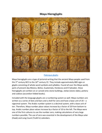
Orienting the SkeletonWhen placing joints, you almost always wind up translating them tomove them into position. This disrupts the orientation of the parent tothe child by moving the child so the parent no longer points at the child.This results in unpredictable rotations as shown below.Rotating the parent jointaround the X axistwistst the jointcausing the middlejoint to rotatepredictably with andcarry the end joint inan arc.Moving the middle jointback in Z and over in Xalong the middle joint’sX axis causes the whole jointassembly to rotatecompletely out ofwhack!Therefore: Jointorientation is crucial.Each joint has what is called a Local Rotation Axis. This axis will be knownhenceforth as the LRA. It reflects how the joint is oriented. You can seethem by choosing Display Component Display Local RotationAxes.
You may edit them manually by going into component editing mode (pressF8) and activate them by LM clicking and holding on the ? mark in theComponent Selection Mask toolbar.This will allow you to change the orientation of each joints’ LRA thuschanging the directions of each joint’s rotation.Our task is to set the LRAs of each joint in our skeleton so as to facilitatecreating controls for our rotations. There are over 75 joints in ourskeleton. Manually rotating each joint’s LRA is not only inefficient, it isalso VERY inaccurate.
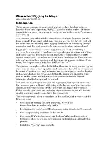
Michael Comet’s cometJointOrient MEL ScriptFortunately, there is a tool that isthe gold standard forchanging joint orients. It iscalled cometJointOrient.mel.You can access it from theekCharacterToolKitinterface. It is the rightunder Comet Rename and iscalled Comet JointOrient.Note: If you download this scriptfrom highend3D or fromcomet-cartoons.com, therewill not be a Select Hierarchybutton. I added thiscommand as a time savinghelp to this script.Orienting the Spine JointsWe will use this script to orient thejoints in the skeleton startingwith the spine. But first, weneed to select the joints wewant to change. To do this, wewill use Maya’s quick selectfield located at top right. LMclick on the sel button andchoose Quick Selection from thepopup field. Then type“*Spine*” as shown below:
Pressing Enter selects all the jointswith the string Spine in thename. This includes the CSpineJoint.1.In the cometJointOrientinterface, press the Show AxisButton.2.You should see all the axesrevealed as shown at left.Note that the bottom 4 joints arereversed when compared to thetop 7. We need to change this.3.Set the cometJointOrient asshown at left.4.Press Orient Joints, and youwill see the joints align. TheAim Axis specifies the axis thatwill point down the joint. Wewant to set that to X. The UpAxis specifies which axis wouldpoint upward. Set this to Y.But keep in mind that thesejoints are not oriented to pointthe Y axis along the World Yaxis, we will set the World UpDir (ection) to force the Y axisto point the way we want. Pressthe Z button next to the WorldUp Dir fields, and uncheckAuto-Guess Up Direction. Thiswill cause the Y axis to pointtoward the front. If we were toenter –1 in the Z field, the Yaxis would point toward theback.
Switch to the Rotate tool (press e) to rotate the spine forward. You willsee all the joints bending forward predictably. This is good. Press z toundo this motion.Lastly, press the Hide Axes button to hide the LRAs of the Spine joints.There, that wasn’t so bad, was it?Orienting the Neck, Head and Jaw JointsOnce you begin to get the feel of doing this, it becomes much easier. Solets orient the head, neck and jaw joints as follows1.Select the neck joint. (That isthe one right above CSpine).2.Press the Select Hierarchybutton.3.Set the cometJointOrientwindowAim Axis: XUp Axis: YWorld Up Dir 0.0 0.0 1.0Auto-Guess unchecked4.Press Orient Joints and youshould see them oriented asshown at left.
Hmm, this worked for the Neck andHead joints, but the face andjaw joints have the Y and Zaxes facing the wrong direction.Let’s change that as follows:5.Next Select the FaceBase joint.6.Press Select Hierarchy.7.This time set thecometJointOrient window asshown. Basically, just check theReverse box next to the UpAxis. This will reverse thedirection of the Y axis. Takingthe Z axis with it.8.Press Orient Joints and the Yaxis will flip flipping the Z axisas well!9.Select the Neck joint andchoose select hierarchy.10. Click the Hide Axis buttonThat’s much better! Actually, thisstep will allow one of the laterscripts to automatically rig thejaw to open and close, so it isquite important.
Orienting the ArmsOne of the most important things to remember when rigging is that allyour controls should have your Translate, Rotate and Scale valueszeroed out. With joints, you can’t have the Translates zeroed out, butRotates must be. The good news is that cometJointOrient zerosRotations out easily, and that is what we must do for the arm. Let’sdo that as follows:1.Select Osw DEFCollar L.2.Hold down the shift key andselect the Shoulder, Elbow,Forearm, Wrist and Palmjoints.3.In cometJointOrient, press theShow Axis button.4.Using the settings shown atleft, orient the joints properly.The only difference here is thatwe have set the World Up Dirto be 0.0 1.0 0.0 by clicking onthe Y button on that line.5.Press Hide Axis to hide theLRA.6.Repeat steps 1-5 for the Rightarm, but this time, click theReverse box for both the AimAxis and Up Axis lines. Thiswill orient the arms properlyfor this side.This should be getting a littleeasier. Now let’s move on to thefingers. pa
Aug 15, 2008 · The Maya System of Joints and Bones Maya joints are a type of deformer that are designed to transfer rotational values to points on a model based on each joints influence on those points. Joints are most often arranged in a hierarchy–meaning that one joint is