Transcription
Data Logging Display Module Product ManualRevision 2.1An Ewert Energy Systems, Inc ProductThe Orion BMS and this display module are designed and manufactured by EwertEnergy Systems, Inc. Ewert Energy Systems is a research & development companyfocusing on developing solutions for plug-in hybrid and electric vehicles and otherenergy storage applications. Ewert Energy provides custom solutions as well as off theshelf components.
Data Logging Display ModuleTable of ContentsProduct Description . 3Product Specifications . 3Ordering Options . 3Installation & Wiring . 4Wiring Diagram .4Description of Wiring Connections .4Standard Connection to the Orion BMS .5System Operation . 6Description of LED illuminations .6Memory Card . 6Configuring the Data Logging Display . 7CANBUS Settings Tab: .8Log File Maintenance Tab: .9Cell Voltage Logging Settings: . 10Display Settings Tab. 12Setting the Clock & Monitoring Live Diagnostic Data . 13Displaying or Converting Log Files . 14Troubleshooting . 16Flashing LEDs on the display can indicate various error states . 16Electrical & Product Specifications . 17Product Dimensions . 17Product Weight . 17Connector . 17Electrical Specifications . 172
Data Logging Display ModuleProduct DescriptionThe CAN Data Logger and Display module for the Orion BMS / Orion Jr. BMS (CAN version only)provides visual feedback of the essential information on a battery pack as well as data loggingcapabilities for diagnostics. This display and logging combo connects to an Orion BMS unit via CAN(Controller Area Network) and logs data to a memory card while displaying State of Charge, PowerLimited (reduced output power), and the Malfunction Indicator Status (error indicator)Product Specifications Operates with the Orion BMS and Orion Jr. BMS (CAN version only) from Ewert EnergySystems (BMS sold separately) Full automotive operating temperature range (-40C to 80C) Logs BMS parameters to memory card at user selectable sampling rate Compact size and shape Connects to the Orion BMS via CAN (no analog connections) Supports brightness dimming for automotive use (via CAN) External “event trigger” input which can flag events for future review Log graphing and analysis software Real time clock to store data and time of each charge / discharge cycle Supports CAN frequencies of 125, 250, 500Kbps, and 1 Mbps User customizable logging frequency from 100mS to 10 secondsOrdering OptionsThe CAN data logging and display module can be ordered without an enclosure for easy integrationinto other enclosures. Contact Ewert Energy for this ordering option.3
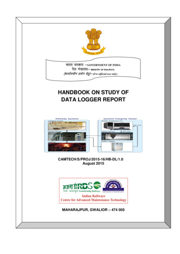
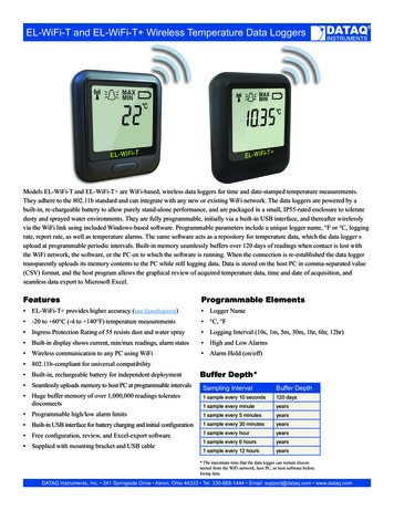
Data Logging Display ModuleInstallation & WiringThe diagram below includes some signal wires that come from the Orion BMS. For information onsignals connecting to the Orion BMS, please consult the Orion BMS wiring diagram (available athttp://www.orionbms.com/support).Wiring DiagramLooking into back of connector (wires coming towards viewer)Description of Wiring ConnectionsSignal NamePower A ( 12v)DescriptionThis is power source A for the display module and should readapproximately 12v. Either power source can fully power themodule and will not back feed the other power source. This istypically connected to the same READY power source as theBMS.Power B ( 12v)This is power source A for the display module and should readapproximately 12v. Either power source can fully power themodule and will not back feed the other power source. This istypically connected to the same CHARGE power source as theBMS.Ground (NEG)12V Power ground for the display module. This ground MUST beconnected to the same ground / chassis that the Orion BMS isconnected to.Event TriggerThis input is designed to mark an event in the log file. Mostcommonly this is connected to a momentary switch the user canpress to flag an event they want to review later in a data log. Shortthis output to ground to record an event.CAN High and CAN LowThese are the 2 CAN BUS connections. These are connected tothe Orion BMS using shielded twisted pair cable. There is no CANtermination inside the module.4
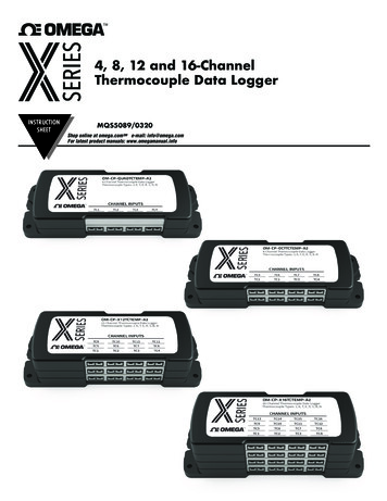
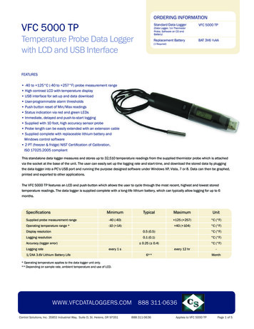
Data Logging Display ModuleStandard Connection to the Orion BMS5
Data Logging Display ModuleSystem OperationWhen powered, the CAN data logging and display module will constantly monitor the CAN BUS formessages from the Orion BMS and will log and display the appropriate information. The Orion BMS unitmust be configured to enable support for this module. Additionally, the data logging module may needto be configured in order to begin logging or to communicate with the BMS if a different baud rate isused.On the display, the bar graph represents the measured voltage at the State of Charge pin, the yellowreduced power indicator represents if the battery is unable to output full power, and the error indicatorilluminates if the BMS detects errors. Additionally, flashing LEDs indicate various status of the displaymodule, such as memory card errors or CAN communication errors, etc.Description of LED illuminations SOC bar graph LEDs (1-10 LEDs correspond to 0-100% SOC.)Yellow power limited LED illuminates if the measured Discharge Current Limit drops below aspecified percentage of the maximum discharge current limit (the default is 70%, but can bechanged by altering the configuration).The red indicator LED illuminates if an error is detected. See the troubleshooting section for moreinformation.Memory CardThe data logging and display module does not ship with a memory card. If the data logging capabilitiesof the module are desired, a card must be acquired and inserted into the unit. The display is compatiblewith any size “micro SD” type memory card up to 32Gb in size.6
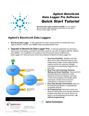
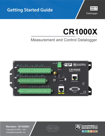
Data Logging Display ModuleConfiguring the Data Logging DisplayEnable the data logging display by checking the box on the “Addon Settings” tab of the Orion BMS orOrion Jr. BMS utility.The Data logger can be configured by using the Data Logging Display Module Utility. The utility can bedownloaded from http://www.orionbms.com/downloads. Settings are uploaded to the Data Logger byplacing the configuration file on the memory card and then inserting that memory card into the datalogging display.Important: The data logging display must be enabled AND configured in order to function!Settings are uploaded to the data logging display either by writing a configuration file to the memorycard and then inserting the card into the display or by connecting to the logging module via CANBUS.While both methods are equally effective at changing the settings, a CANBUS connection has theadded advantage of being able to set the clock and view live data.To change settings, open the Data Logging Display ModuleUtility and click on the “Edit Settings” button. Four tabsappear at the top; the settings on each tab are describedbelow. After settings have been changed, they must eitherbe saved to the memory card or transmitted over theCANBUS to the data logging display module. Press theappropriate button (“Save Settings to Memory Card” or“Send Settings Over CANBUS”) to transmit the settings.If saving to a memory card, the file must be saved in the rootof the memory card with the filename “config n.odc”. Forexample, if your memory card is the H: drive, the file mustbe H:\config n.odc”. When the data logger reads the file, itwill import the settings, delete the “config n.odc” file andcreate a “config.odc” file which will contain the most recentconfiguration information.7
Data Logging Display ModuleCANBUS Settings Tab:CANBUS Baud Rate - This value is the baud rate at which the CANBUS is operating. This must be setto the same baud rate as the BMS and any other devices on this CANBUS network. The Orion BMSdefaults to 500kBps.Logger OBD2 CAN ID - This is the identification code that the data logger will respond to whenconnecting via the PC utility. This ID must be unique to any devices on the CANBUS and cannot be thesame value as the Orion BMS unit.8
Data Logging Display ModuleLog File Maintenance Tab:Max Log Size - This value is the maximum file size in megabytes that the logger will record. If a filebecomes longer than this, the logger will save the file it is currently recording and begin a new log file.To disable this limit and allow any size log file, enter 0 into this field.Max Log Length - This is the maximum amount of time in minutes which the data logger will record. If alog is longer than this, the logger will save the file it is currently recording and begin a new log file. Todisable this and allow any length of time, enter 0 into this field.Logfile Storage Style - The logger can be configured to record only the last 5 log files or to record asmany log files as the memory card will hold. For very small memory cards, storing only the last logs isrecommended, but for larger memory cards it is usually more desirable to start a new log each time.Save logfile data more frequently - This option reduces the likelihood of a corrupted log file. However, itcomes at the expense of not recording information as quickly. For the highest log file resolution, leavethis box unchecked. For applications where reliability is more important than speed, it may be desirableto check this box.9
Data Logging Display ModuleCell Voltage Logging Settings:The Data logging display module has the option to record individual cell voltages. Recording individualcell voltages may be very useful for diagnosing battery pack problems, but it comes at the expense ofrequiring significantly more storage space on the memory card. The exact amount of space requireddepends on the number of cells being monitored and the frequency the messages are being recorded.This feature is disabled by default and requires setup both in the data logging display and on the OrionBMS or Orion Jr. BMS unit. For both BMS units, the CANBUS interface must be configured to transmitcell voltages on the CANBUS and the CANBUS message identifier must be the same on the BMS andon the data logger.To do this, open the Orion BMS or Orion Jr BMS utility and load the BMS configuration into theutility by pressing the “Receive profile from BMS” button and loading the saved profile from disk.Click on the CANBUS Settings tab. Ensure that the box labeled “Enable Battery Cell Broadcast” ischecked. For the Orion BMS, ensure that the proper CANBUS interface is selected. This must bethe CANBUS interface that the Data Logging Display is connected to. Below this, the Battery CellBroadcast Identifier must be selected. This is usually set to 0x36 unless this CAN ID is alreadyused by something else. Once the changes have been made, the profile must be transmitted backto the BMS unit for the settings to take effect.10
Data Logging Display ModuleBack on the Data logging display module settings, insert the value selected for the Battery CellBroadcast Identifier in the field that says “BMS Cell Voltage Broadcast CAN ID” (this value must exactlymatch the value in the BMS to work).Then select the frequency to log individual cell voltages. The fastest supported speed is every 0.5seconds (which will log twice per second.)11
Data Logging Display ModuleDisplay Settings TabThreshold for yellow LED to illuminate (percentage) - The yellow LED on the data logging display canbe used to warn the operator that the battery is not able to output full power for whatever reason. Thissetting controls when the LED will illuminate based on the percentage of power available. The criteriaused for illuminating the yellow LED is based on the discharge current limit vs. the maximum possibledischarge current limit. The yellow low power warning LED can be disabled by selecting “disable.”Show LED Animation While Charging - Selecting this option will cause the SOC bars on the display toprogress in an animation when the BMS is in charge mode and there is charging current flowing intothe battery pack. It is useful for being able to identify when a charger is active.Turn off all LEDs and stop logging when no CAN traffic is present - This option will cause the datalogger to effectively shut down when CAN traffic is not present. Note: While this option conserves somepower, the data logging display module does not have a super low power sleep mode and will stillconsume power when power is applied to the logger.Flash yellow LED when memory card is not present - This option causes the yellow LED to flash atabout a 1 second interval when the module detects that it does not have a memory card loaded orwhen the memory card cannot be written. It is recommended to leave this option enabled unless thedata logger is intentionally being used only as a display with no memory card.Show full SOC bars / Show empty SOC bars when SOC is greater / less than (%) - This option is usedfor showing a user that the battery pack is fully charged or fully discharged when a smaller portion ofthe battery pack is being used (often times for lifespan reasons, only 80% of a battery pack is used.)Enter the maximum SOC and minimum SOC into these fields and the display will adjust the SOC barsaccordingly. For example, if the lower 15% and upper 5% of a battery is not being used, the effectiveusable range of the battery is from 15% - 95% SOC. In this case, 15% would be entered into “ShowEmpty SOC Bars When SOC Is Less Than (%)” and 95% would be entered into “Show Full SOC BarsWhen SOC Is Greater Than (%)12
Data Logging Display ModuleSetting the Clock & Monitoring Live Diagnostic DataThe module contains a real time clock used for creating timestamps for logfiles. Over time it may benecessary to set the clock. This is especially true if the module is left sitting without power for a periodof several months which may lead to an internal battery that is discharged.Setting the clock or monitoring live data information from the display module requires connecting thePC to the CANBUS that the data logging display is connected to via a CANdapter. Only a CANdapterbrand USB to CAN adapter can be used for this connection; other CAN to USB adapters will not work.Additionally, to communicate with the data logging display, the display must be powered by either of thetwo power sources.To set the clock, first ensure that the clock on the computer is accurate. Then click the “Set Clock”button. A dialog will pop up asking to select a CANdapter and a baud rate. Select the CANdapter andthe proper baud rate and press Connect. The clock will then be updated.Likewise, to view live data on the performance of the data logging display module, click on the “LiveData” button. The utility will pop up a dialog asking to select the CANdatper and baud rate. Afterselecting those and pressing Connect, a window will appear showing diagnostic information from thedata logging display. Live data parameters are sometimes helpful for diagnosing issues and can beused to determine the version of firmware on the Data Logging Display module.13
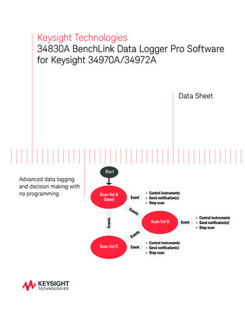
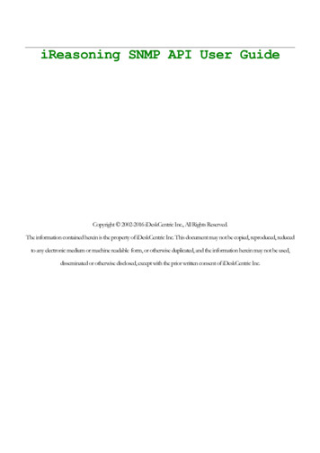
Data Logging Display ModuleDisplaying or Converting Log FilesLog files from the data logging display can be either graphed through the utility or be saved as CSVfiles which can be imported into other graphing or analysis software. The files stored on the memorycard are in a compressed binary format which must be interpreted using the data logging displaymodule.To display a log file:With the memory card inserted into a card reader, click the “Chart Logfile” button on the utility. Selectthe location of the memory card or press auto-detect for the utility to attempt to automatically locate thememory card. Once the proper location for the memory card has been selected, a list of available logfiles will appear. Select the log file you would like to graph and press “Chart Selected Logfile.” The utilitywill then open one or two graph windows depending on whether individual cell voltage logging isenabled or not. One window will contain the BMS parameters while the second window will containindividual cell voltages and pack amperage if individual cell logging is enabled. On the left hand side,select the parameters you wish to view. Larger logs may require a significant amount of time andprocessing power to display.Example charts of log files14
Data Logging Display ModuleTo convert a log file to CSV format:With the memory card inserted into a card reader, click the “Convert Logfiles” button. Select thelocation of the memory card or press auto-detect for the utility to attempt to automatically locate thememory card. Once the proper location for the memory card has been selected, a list of available logfiles will appear. On this list, multiple log files can be selected for export at the same time. Afterselecting the logfiles to convert, press the “Convert Logfiles” button at the bottom. A dialog will appearasking for a location to export the files. Select a desired location, ensuring that you have proper filepermissions to save documents to this location. The utility will then begin converting the log files.Depending on the size, it may take a considerable amount of time to convert. A dialog showing thestatus is displayed during the conversion process. If individual cell voltage logging is enabled, two fileswill be generated for each log file, one with the BMS parameters, one with the individual cell voltages.Once completed the “Open containing folder” button will open up a file manager window with theconverted files.15
Data Logging Display ModuleTroubleshootingFlashing LEDs on the display can indicate various error statesYellow LED fast blink: memory card fullYellow LED slow blink: memory card missing or invalidYellow LED solid: Discharge current limit reduced on BMSYellow LED quick single flash: User triggered eventRed LED slow blink: The logger has lost CAN connectivity with the BMSRed LED fast blink: CAN in error passive state (CAN lock down)Red LED solid: Error code present on BMSRed & yellow LED blink slow at the same time: The data logger is updating configuration settings or theconfiguration is invalid.Problem SymptomLikely Causes & SolutionsVerify that least one of the power sources (A or B) isNone of the LED indicators will turn on. powered with 12v DC. Also verify that the ground tothe basic display module is connected properly.The display module will not turn off.16The data logging display module is designed to stayon whenever it is powered (it can be powered by"Power A" or "Power B"). To turn the display moduleoff, ensure power is removed from both powersources. Only one power source is necessary to turnon the display.
Data Logging Display ModuleElectrical & Product SpecificationsProduct Dimensions2.7 in [6.9 cm] (W) x 1.9 in [5.0 cm] (L) x 0.78 in [2.0 cm] (H)Product Weight1.7 ozConnectorConnector is Molex part number 0050579406Electrical SpecificationsItemSupply VoltageSupply CurrentOperatingTemperature17Min10-Max16-Typical65 (all LEDs on)UnitsVdcmA-4080-C
Back on the Data logging display module settings, insert the value selected for the Battery Cell Broadcast Identifier in the field that says "BMS Cell Voltage Broadcast CAN ID" (this value must exactly match the value in the BMS to work). Then select the frequency to log individual cell voltages. The fastest supported speed is every 0.5