Transcription
E U C L I DI N D U S T R I E LE SEVEN
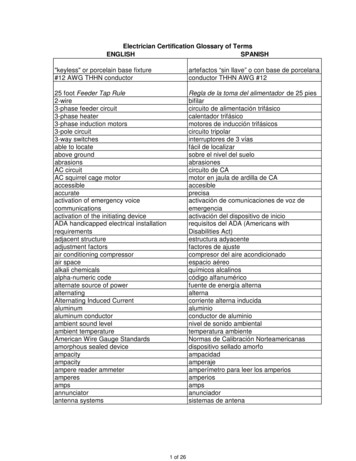
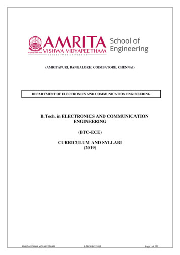
TECH TIPSELECTRICAL SYSTEMSHEAVY-DUTY ELECTRICAL SYSTEMS days basic heavy-duty electrical systemconsists of batteries, a starting motor, analternator, and the control circuit. Thecontrol circuit includes a magnetic switch,ignition switch, push button switch, and allthe required wiring.The batteries provide the high electricalcurrent needed by the starting motor. Themagnetic switch controls the batterycurrent into the starter solenoid. Theignition and push button switch activate themagnetic switch, which in turn activates thestarting motor. If all functions workproperly, the engine should turn over.Magnetic SwitchMechanical energy from the running engineFig. 1provides the power needed to operate thealternator. The alternator creates electrical energy that recharges the batteries and provides the currentfor the vehicle’s electrical accessories and loads. The wiring should be of adequate size to carry theamount of current needed in each circuit.StarterWhen these components are properly matched, they provide a balanced electrical system that will performwell through out its life expectancy.SYSTEM COMPONENT FUNCTIONSBATTERYA battery is a storage unit that can store and produce electricalenergy. With use, they gradually deteriorate and become less capableof performing their important task.There are three basic types of batteries used in heavy duty electricalsystems:Filler capThese are lead- acid batteries with a high degree of a base elementcalled antimony in the grid alloy. Because of this base element, theyrequire frequent servicing, particularly the need for adding water.Semi-maintenance freeThese are conventional batteries with reduced amounts of antimonyin the grid alloy. Consequently, servicing is reduced but water stillmust be added periodically.1Fig. 2
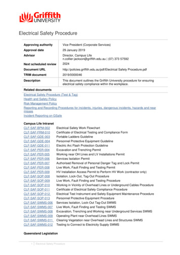
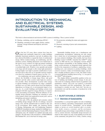
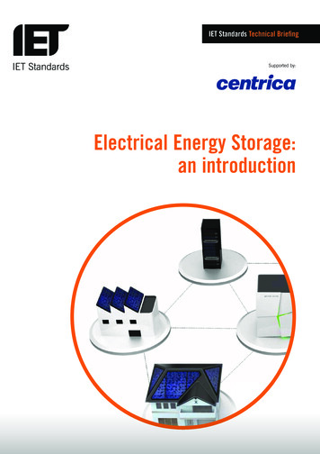
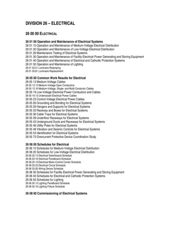
TECH TIPSElectricalMaintenance freeThese batteries use a lead- calcium grid alloy without antimony. They never need water, nor are provisions provided for adding water.STARTERAll starters, from the smallest to the largest; automotive, industrial, heavy truck, off road equipment, arevirtually the same. They are simply electrical motors that convert electrical energy into mechanical energyto crank the engine.SolenoidLever HousingAssemblyBattery StudCommutator EndFrame & BrushAssemblyDrive HousingGroundStudDriveAssemblyArmatureSolenoidFig. 3ALTERNATORAn alternator is a generator that produces alternating current from mechanical energy. The use of rectifiers or diodes converts the alternating current to direct current. The direct current is used to maintain acharge in the battery and handle the electrical loads of the ingRectifierBridgeRotorFig. 42
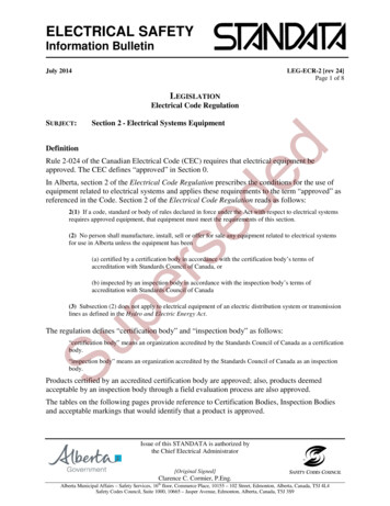
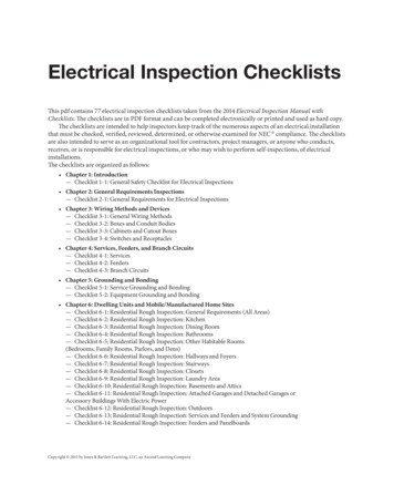
TECH TIPSElectricalWIRING CIRCUITSCranking circuitThe cranking circuit consists of large cables that carry the high starter current from the battery to thesolenoid. Excessive voltage loss in the circuit causes slow cranking speeds, especially in cold weather.Slow cranking can lead to starter burn up if cranked over 30 seconds. Batteries that become deeplydischarged can cause the same problem.Solenoid Control CircuitThe solenoid circuit consists of the wiring from the batteries through a push button or magnetic switch tothe battery "SW" (switch) terminal of the starter solenoid and back to the battery. Excessive voltage lossin this current can cause the solenoid to shift in and out (chattering) which will result in the vehicle notstarting. This condition can result in a burned contact disc or terminals of the starter solenoid. When amagnetic switch is used, excessive voltage loss will also cause this switch to open and close continuously.Again, batteries that become deeply discharged or worn out will cause the same condition.Charging CircuitThe charging circuit consists of the wiring between the alternator and battery. Excessive voltage loss inthe circuit will prevent the batteries from being properly charged. Complete failure of the charging circuitcan cause alternator damage and/or failure.Battery cable size and connectionsThe connections and cable size have aTOTAL CIRCUIT LENGTH GAUGEsignificant effect on the electrical system.Up to 144"The jumper lines between batteriesshould be at least #00 gauge cable. The144" to 180"length of the circuit has a bearing on the180" to 230"amount of voltage loss which occurs inChart A2each cable. Be sure that all the circuitscan handle the required load. (Refer tochart A2). The total length of a circuit is the sum of both sides of the circuit.CABLE GAUGE#00#000#0000Corrosion and loose connections, the two largest failure causes, can be minimized by taking precautionswhen installing cable ends. Many times these two go hand in hand. Corrosion will cause the connectionsto loosen. Corrosion travels through cables,causing voltage losses. To prevent corrosiontrouble, seal all exposed areas. When using crimpstyle ends that are open ended, seal by solderingthem closed. Wire that is exposed to the elementsshould be sealed by using shrinkable tubing.Fig. 53
TECH TIPSElectricalEnergizing AlternatorsSometimes a new alternator will not charge because the magnetic fieldhas been lost through long shelf life or jarring during shipping andhandling. The magnetic field can be energized by following these steps.Momentarily connect a jumper lead from the battery positive terminal ( )on the alternator to the relay (R)or indicator (I) terminal. This procedurewill restore the normal residual magnetism.Fig. 6BASIC ELECTRICITYCurrent Electron FlowCurrent is the flow or movement of electrons. You can compare this to the flow of water. Without pressure (voltage), the current will not flow. Ampere (amps) is the unit of measure for electrical current.Fig. 7Voltage Electrical PressureVoltage provides the electrical pressure or force that causes current to flow. Voltage is the difference inelectrical pressure between two points in a circuit.Fig. 84
TECH TIPSElectricalResistanceResistance is a restriction of current flow. If resistance increases, current flow decreases. This can bedetected by voltage loss in a circuit. Ohm is the unit of measure for resistance.Fig. 9Magnetic FieldWhen forcing current through a conductor, a magnetic field is produced. Magnetic fields and direction ofcurrent flow are factors to consider when using ammeters, especially when using induction pick up ammeters.Fig. 10Formulas and DefinitionsAll the electrical characteristics are interrelated. The basic formulas are:I E/RE R IR E/IAmperes Volts / OhmsVolts Ohms x AmperesOhms Volts / AmperesAmps (Amperage) — measure of current flow in a circuitOhms (Resistance) — measure of resistance in a circuitVolts (Electromotive force) — measure of the force that drives current flow in a circuit5
TECH TIPSElectricalQUICK REFERENCE TROUBLE SHOOTING GUIDESymptomCauseStarter drags, slow or sluggish crankingDischarged batteryLoose or dirty connectionsCorroded or damaged cablesSolenoid chatters, won’t engage thestarter driveDischarged batteryLoose or dirty connectionsProblems in the solenoidor magnetic switch circuitStarter will not operate at allStarter relay problemBurned out solenoidFaulty ignition switchOpen wire in cranking circuitCompletely dead batteryStarter motors but will not engagethe engine flywheelDamaged or worn ring gearWrong starter driveIncorrect mounting hole sizeStarter will not disengage when keyis releasedDamaged or worn ring gearStarter loose on mounting hardwareStarter relay or solenoid problemFaulty ignition switchBatteries won’t hold a chargeLoose or dirty connectionsCorroded or damaged cablesBad cell or cells in battery(s)Bad groundLoose or worn out belts or pulleyAlternator will not chargeAlternator rotor has lost residual magnetismPulley is wornLoose or worn beltsBad groundCorroded or dirty connectionsAlternator doesn’t charge at low RPMWrong pulley diameter which causes alternator tospin too slowly at low engine RPMAlternator is overchargingDischarged battery or batteriesBad cell(s) in batteryRegulator has failedHigh Alternator noise levelWorn out bearing in alternatorFrayed or worn beltLoose fan or pulleyAlternator mounting loose6
TECH TIPSElectricalELECTRICAL GLOSSARYTHE LANGUAGE OF CHARGING AND STARTING SYSTEMSGROUND — The part of an electrical circuit used toreturn current from the participating unit to its source.ALTERNATOR — A device which converts mechanicalenergy to electrical energy. It maintains the battery in afully charged state.HYDROMETER — The instrument which measuresspecific gravity. In a battery it measures the weight ofthe electrolyte in relation to the weight of pure water.AMPERE — The unit measure of electrical currentflow. This movement can be compared to the flow ofwater through a pipe.INDUCTION — The current induced in a conductorwhen the conductor cuts across a magnetic field.ARMATURE — Any part moved by magnetic attractionor repulsion. An example is the armature in a starter.MAGNETIC FIELD — The gap or space around amagnet in which the magnetic lines of force travel.BATTERY — A device for storing energy and convertingchemical energy into electrical energy.OHM — The unit of electrical measurement ofresistance to the flow of current in a circuit.BRUSH — A block of conducting substance, usuallymade of carbon, which picks up or delivers electriccurrent from, or to, the commutator or slipper ring.OPEN CIRCUIT — A circuit which is broken so thatelectric current cannot flow.BRUSH HOLDER — Holds the brushes on an alternatoror starter in position on the commutator or slipper rings.OVER-CRANK PROTECTION — A temperaturelimiting switch built into a starter. It preventsinternal damage due to extended operation causedby extreme low temperatures or batteries in a lowstate of charge.CHARGE RATE — The amperage flowing from thealternator to the battery.CIRCUIT — The path over which a current of electricity flows.PARALLEL CIRCUIT — An electrical circuit inwhich the electrical units and conductors are connected so that the current flows over several independent paths.COLD CRANKING AMPS. — The number ofamperes a battery at zero degrees fahrenheit can deliverfor 30 seconds and maintain a voltage of 1.2 volts percell or higher.PINION — The gear portion of the starter drivemechanism which engages the flywheel ring gearwhen rotated by the starting motor armature.COMMUTATOR — A cylindrical device mountedon one end of an armature shaft. It is composed ofcopper segments insulated from each other. Theends of the armature windings are soldered to pairsof segments.RECTIFIER — Any device, such as the diode in analternator, which changes alternating current to directcurrent.DRIVE END — The end of a starter that contains thepinion gear or "Bendix", or the end of an alternatorwhich is driven by a belt or a gear.RESISTANCE — The opposition offered to thepassage of electrical current through a body orsubstance. The ohm is the unit of resistance.ELECTROLYTE — A solution of sulfuric acid andwater used in batteries.REGULATOR — A device for sensing a battery'ssupply of electrical energy. The regulator limits thealternators output voltage and keeps the currentoutput of the alternator in step with the speed ofthe vehicle and the demand of the various accessories and the battery.FIELD COILS — A coil of insulated wire which formsthe windings of a starter.FIELD HOUSING — The center section of a crankingmotor (starter) that holds the field coils.ROTOR — The rotating member of an alternator thatprovides the magnetic field needed to produce anelectrical current.7
TECH TIPSElectricalELECTRICAL GLOSSARYTHE LANGUAGE OF CHARGING AND STARTING SYSTEMSSERIES CIRCUIT — A circuit in which the currentpasses through each electrical unit in succession.SOLENOID — An electromagnetic device used toperform a mechanical operation. A truck startersolenoid moves the drive pinion to mesh with theflywheel ring gear and holds it in position while thearmature of the starter motor rotates to start the engine.SHORT CIRCUIT — A path of lesser resistancewhich allows current to bypass its prescribed path.STARTER — The electrical motor which convertsthe electrical energy of the battery to the mechanicalenergy required to start the engine. Also called acranking motor or starting motor.SLIP RING — A collector ring on the end of a rotorupon which the brushes ride.VOLT — The unit of electrical pressure or electromotiveforce.STATOR — The name of the laminated steel ringwith loops of copper wire that surrounds the rotor inan alternator.WATT — This unit of electrical power is calculated bymultiplying amperes times voltage in a circuit. Onehorsepower equals 746 watts.The Most Trusted Name In Truck Parts.8
Other Euclid TechnicalTraining Modules Available:Module One - Foundation Air BrakesIncludes:Foundation Air Brake Hardware KitsCamshafts/Camshaft Repair KitsAutomatic Slack AdjustersAir Wedge BrakesModule Two - Hydraulic BrakesIncludes:Hydraulic Wheel CylindersMaster CylinderHydraulic Disc Brake RotorsHydraulic Disc Brake CalipersModule Three - Wheel Attaching PartsIncludes:Disc Wheel PartsSpoke Wheel PartsModule Four - SuspensionsIncludes:Four-Spring SuspensionsNeway Air SuspensionsMack Camel BackSpring SuspensionU-BoltsUni-Rods/Maxi-RodsAir SpringsShock AbsorbersModule Five - Front End PartsIncludes:King Pin SetsTie Rod EndsDrag LinksLight-Duty Front End PartsModule Six - Air Conditioningand Heating PartsModule Eight - Engine Cooling SystemsIncludes:Water PumpsEUCLID INDUSTRIES, INC.6660 Beta Drive, Cleveland, OH 44143-2321(216) 451-4300 FAX (216) 461-4307TT-73-97EUCLID INDUSTRIES CANADA Ltd.Toronto Edmonton Montreal Vancouver
ELECTRICAL SYSTEMS 1 HEAVY-DUTY ELECTRICAL SYSTEMS BASICS Todays basic heavy-duty electrical system consists of batteries, a starting motor, an alternator, and the control circuit. The control circuit includes a magnetic switch, ignition switch, push button switch, and all the required wiring. T