Transcription
Solar Photovoltaic Power Plant Modelingand Validation GuidelineMVWGDecember 9, 2019
Solar Photovoltaic Power Plant Modeling and Validation GuidelineTable of ContentsIntroduction .5Guideline Criteria .5Power Flow Modeling .6Dynamic Modeling .6Model Validation Procedure .7More Information .7Background .81Power Flow Representation .111.1Central Station Solar PV Systems .11Implications of Collector System Equivalencing .13Interconnection Transmission Line .13Solar PV Plant Substation Transformer .13Plant-Level Reactive Compensation .13Equivalent Collector System .13Equivalent Inverter Pad-Mounted Transformer .16Equivalent Generator Representation .16231.2Representation of Distribution-Connected Solar PV Systems .211.3Modeling during post transient power flows.22Dynamic Modeling .232.1Active Power/Frequency Control .232.2Reactive Power /Voltage Control .232.3Fault Ride-Through and Representation of Protection Limits .23WECC Generic Models .253.1Technical Specifications for the WECC Generic Models .253.2WECC Generic Model for Large-scale solar PV Plants .26Model Structure .26Model Invocation .27Scaling for the Solar PV Plant Size and Reactive Capability .282
Solar Photovoltaic Power Plant Modeling and Validation GuidelineReactive Power/Voltage Controls Options .28Active power control options .30Current Limit Logic .30Representation of Voltage and Frequency Protection .30Momentary cessation .31Consideration for modeling solar PV and battery storage hybrid plant .323.34WECC Generic Model for Distributed and Small Solar PV Plants .33Model Parameterization and Validation .344.1Data Collection .344.2Defining the Mode of Operation .35Setting the REPC Model Flags .35Setting the REEC Model Flags .36Setting the REGC Model Flags.414.3Valid Model Parameter Flag Combinations .41Strictly Local Control—No REPC Module .42Plant-Level Control—Model Includes REPC Module .424.4Dynamic Model Invocation Considerations .45REPC Module Invocation Considerations .454.5Populating Model Parameters .46Dynamic Model Parameter Sensitivity .47Real Power Response to Voltage Variations .47Real Power Response to Frequency Variations .47Reactive Power Response to Voltage Variations.47Reactive Power Response to Frequency Variations .48Properly Coordinated Plant Control and Inverter Control .48Parameter Estimation Example.48Importance of Power Flow Representation.52Model Performance for Various Disturbances .525Conclusion .543
Solar Photovoltaic Power Plant Modeling and Validation Guideline6Appendix .556.1Short-Circuit Ratio Fundamentals .556.2REGC A Block Diagram and Model Parameters.576.3REEC A Block Diagram and Model Parameters .616.4REPC A Block Diagram and Model Parameters .646.5SAMPLE SOLAR PV POWER PLANT DATA REQUEST .66Version History .684
Solar Photovoltaic Power Plant Modeling and Validation GuidelineIntroductionAlong with development of the second-generation generic renewable energy system (RES) dynamicmodels, WECC Modeling and Validation Work Group has set up several guidelines for modeling bulkpower system (BPS)-connected solar PV plants: Central Station Photovoltaic Power Plant Model Validation Guideline; dated June 17, 2015. WECC solar PV Power Plant Dynamic Modeling Guide; dated April 2014. WECC Guide for Representation of Photovoltaic Systems in Large-Scale Load Flow Simulations;dated August 2010.The second-generation RES models represent most of the solar PV plants in the WesternInterconnection. The guidelines above have been referred to extensively in producing the models forthe solar PV plants. However, recent solar PV tripping events1 due to system disturbance revealedsome weakness of the modeling approach. At the same time, FERC has imposed new technicalrequirements on solar PV generating resources, such as FERC Order 827 and FERC Order 824. Themodeling guidelines need an update to include lessons learned and consider alignment with thetechnical requirements.This document examines the representation of BPS-connected solar PV plants in both power flow anddynamic data sets for BPS studies. The document outlines modeling techniques for all solar PVresources in the transmission and distribution systems. It also shows best practices for modelvalidation of utility-scale solar PV systems ( 20 MVA) connected to the transmission network (60 kVand above).Guideline CriteriaThis is a consolidated document that augments and updates the following guidelines: 21 Central Station Photovoltaic Power Plant Model Validation Guideline; dated June 17, 2015 WECC Solar Plant Dynamic Modeling Guide; dated April 2014NERC disturbance il-May-2018-Fault-Induced-Solar-solar port.aspxApproval of this guideline will supersede the listed guidelines; the latest technical guidance should be used formodeling BPS-connected solar PV resources.25
Solar Photovoltaic Power Plant Modeling and Validation Guideline WECC Guide for Representation of Photovoltaic Systems in Large-Scale Load Flow Simulations;dated August 2010The audience for this guideline includes solar PV plant owners who perform model validation, andtransmission planners who verify validation data and develop interconnection-wide base cases of theirplanning areas.Power Flow ModelingEach central station solar PV plant ( 20 MVA and connected to 60 kV and above) is modeled explicitlyin the power flow model. The power flow model includes: An explicit representation of the interconnection transmission line; An explicit representation of all station transformers; An equivalent representation of the collector systems; An equivalent representation of inverter pad-mounted transformers with a scaled MVA rating; An equivalent representation of generators scaled to match the total capacity of the plant; and An explicit representation of all plant-level reactive compensation devices either asshunts (fixed or switchable) or as generators (FACTs devices), if applicable.The small or distribution-connected, in-front-of-the-meter solar PV plants may be aggregated at a highvoltage bus represented in the power flow. The power flow representation includes: A pseudo-transmission line (jumper) from the aggregated generator to the point of delivery;and The aggregated generator matching the total capacity of multiple plants that can be delivered tothe point of delivery.The behind-the-meter distributed solar PV are represented as aggregated distributed generation part ofthe load.Dynamic ModelingThe dynamic model of a central station solar PV plant explicitly modeled in the power flow includes: A generator/converter module representing the typical solar PV inverter in the plant, scaled-upto match the plant’s aggregate nameplate rating. A local electrical control module which translates real and reactive power references intocurrent commands. A plant-level control module which sends real and reactive power references to the localelectrical controller, if the plant-level control is put in place. Frequency and voltage protection modules, which show inverter protection settings underabnormal frequency and voltage conditions.6
Solar Photovoltaic Power Plant Modeling and Validation GuidelineThe dynamic model of solar PV plants connected at the distribution system represented by anaggregated generator in the power flow includes: Stand-alone DER A model or PVD1 3 modelBehind-the-meter distributed solar PV resources are modeled by the DER A component of thecomposite load model.Model Validation ProcedureThe steps of a successful model validation procedure are: Gather available data from commissioning tests, field tests, and grid disturbances; Clearly define the mode of operation, or control mode, of the plant; Work with the inverter manufacturer, system integrator, or plant operator to determine asmany model parameters as possible beforehand; Minimize the set of dynamic model parameters that are available for tuning or parameterestimation; and Use proper engineering analyses, including tests and tuning, to bring measured and simulateddata into agreement.More Information WECC Generating Unit Model Validation Policy https://www.wecc.org/Administrative/WECCGenerating Unit Model Validation Policy.pdf WECC Generating Facility Data, Testing, and Model Validation Requirementshttps://www.wecc.org/Reliability/WECC Gen Fac Testing and Model Validation Rqmts v 7-132012.pdf WECC Data Preparation Manual https://www.wecc.org/Reliability/2020 WECC DataPreparation Manual.pdf NERC reliability guideline on power plant model verification for inverter-based resourceshttps://www.nerc.com/comm/PC Reliability Guidelines DL/PPMV for InverterBased Resources.pdfPVD1 models were used before the approval of DER A model. For newly interconnecting solar PV plants at thedistribution system, DER A must be used.37
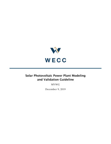
Solar Photovoltaic Power Plant Modeling and Validation GuidelineBackgroundThe composition of the generation fleet in the Western Interconnection is rapidly changing. Asrenewable energy plants have increased in capacity, standards and policies have been developed toensure power flow and dynamic data sets accurately represent the plants. In particular, the latestversions of NERC MOD-026 and MOD-027 apply to all BES generating facilities with an aggregatenameplate rating of 75 MVA or larger. The standards, which are subject to enforcement, requireaccurate representation of a BES generating facility’s reactive power response to system voltagevariations, and its real power response to system frequency variations. Although these standards onlyapply to facilities with an aggregate nameplate rating of 75 MVA or larger, WECC policy is morestringent. It requires the submission of the same data for all plants connected to the transmissionsystem (60 kV and above) with an aggregate nameplate rating of 20 MVA or larger. The WECCGenerating Unit Model Validation policy requires generating facility data to be updated at least onceevery five years.As the penetration of solar PV generation increases, the dynamic response of the system changes, inpart due to a decline in inertia provided by thermal power plants. To conduct accurate planningstudies and ensure the grid operates reliably, variable generation must be modeled with the sameprecision as synchronous generation. The goal is for the time domain simulation to match reality asclosely as possible. Over many years, and with input from manufacturers, the WECC RenewableEnergy Modeling Task Force (REMTF) has developed a suite of generic models for renewable energyplants and established guidelines for modeling solar PV plants— Central Station Photovoltaic Power Plant Model Validation Guideline; dated June 17, 2015. WECC solar PV Power Plant Dynamic Modeling Guide; dated April 2014. WECC Guide for Representation of Photovoltaic Systems in Large-Scale Load Flow Simulations;dated August 2010.These guidelines have been used extensively in producing the models for the solar PV plants.However, recent tripping events due to system disturbance revealed some weakness of the modelingapproach. At the same time, the technology is advancing and there are new technical requirements forsolar PV generating resources. The modeling guidelines need an update to include lessons learned andconsider alignment with the technical requirements.Figure 1 shows the typical solar PV plant topology. The models in BPS studies consist of two parts:A power flow model based on station equipment and an equivalent representation of thecollector system, andA dynamic model representing a scaled-up version of the typical solar PV inverter in the plant.To accurately capture the behavior of a solar PV plant, both the power flow representation anddynamic model must be configured correctly using sound engineering judgment and due diligence.8
Solar Photovoltaic Power Plant Modeling and Validation GuidelineFigure 1: Typical Solar PV Power Plant TopologyFor every central station solar PV plant, the power flow model used in planning studies must includean explicit representation of the station transformer(s) and an equivalent representation of the collectorsystem. The impedance of the collector system and the inverter pad-mounted transformer are nonnegligible and should be included in the power flow model. Equivalent solar PV inverters must not beconnected directly to a high-voltage bus or to the low-voltage side of a substation transformer.Over the period of interest for planning studies, the behavior of a utility-scale solar PV inverter isdriven primarily by its software or firmware and application-specific control settings. A keysimplifying assumption of the generic models created by the REMTF is that the dynamics associatedwith the DC side of the inverter are neglected. This was a conscious decision made with industry input.In many cases, the dynamics associated with the DC side of the inverter are dominated by highfrequency content, which is beyond the interest of bulk power system studies.The dynamic model for a central station solar PV plant includes 2 or 3 modules and has between 45 and75 unique parameters, depending on whether a plant controller is in place. The resulting model has ahigh degree of flexibility and can be configured in over 30 unique modes of operation. With such aplethora of available control settings, it is essential to compile as much information about the system aspossible before trying to tune the model parameters. Knowing the time constants and the mode ofoperation, i.e., control mode, of the plant is critical to achieving adequate model validation. Often, thismeans including the inverter manufacturer, system integrator, or plant op
Dec 09, 2019 · As the penetration of solar PV generation increases, the dynamic response of the system changes, in part due to a decline in inertia provided by thermal power plants. To conduct accurate planning studies and ensu re the grid operates reliably, variable generation must be modeled with the s