Transcription
National Aeronautics and Space AdministrationDevelopment of SiC Large TaperedCrystal GrowthPrinciple Investigator: Philip G. NeudeckNASA Glenn Research CenterPresenting Co-Investigator: Andrew J. TrunekOAIJune 10, 2010Project ID #APE027This presentation does not contain any proprietary, confidential, or otherwise restricted informationwww.nasa.gov
OverviewSiC Large Tapered Crystal GrowthTimeline Funding start: Dec. 2009 Project end: Dec. 2011 Percent complete: 20%Barriers Advanced Power Electronics andElectric Machines (APEEM)SiC expense and material quality inhibiting higherdensity and higher efficiency EV power electronics.Budget Total project funding– DoE: 1200K– NASA: 180K Funds received FY09: 0 Funds received FY10: 700K National Aeronautics and Space AdministrationPartnersNASA Glenn Research CenterOhio Aerospace InstituteSest, Inc.Oak Ridge Assoc. Universities2
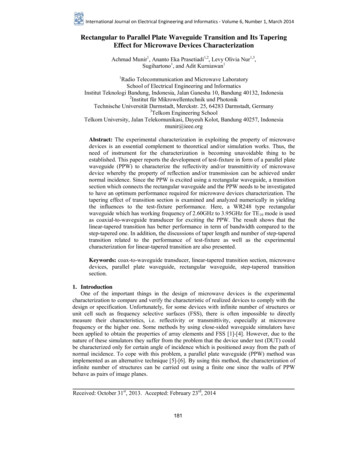
Objectives SiC power semiconductor devices should theoretically enable vastly improved powerconversion electronics compared to today’s silicon-based electronics. 2-4X converter size reduction and/or 2X conversion loss reduction (theoreticalperformance gains vary with system design specifications). Fundamentally improved implementation of smart grid, renewable energy, electricvehicles, aircraft and space power systems. SiC wafer defects and cost inherent to existing material growth approach presentlyinhibiting large benefits from becoming widely & reliably available. New but unproven NASA “Large Tapered Crystal” SiC growth concept proposed toremove SiC material technology barrier.Graphical illustration ofpower converter sizereduction modeled byusing SiC devices insteadof silicon power devices.SiliconSiC(theory)National Aeronautics and Space Administration3
ObjectivesFACT: Majority of large benefits (of significantly higher efficiency andpower density) theoretically enabled by wide bandgap semiconductor(e.g., SiC and GaN) power devices to power systems (includingelectric/hybrid vehicles) have not been realized/commercialized.High cost and high dislocation defect density of starting SiC & GaN wafermaterial are widely recognized as major inhibitors to realizing widebandgap power devices for large system benefits.Overall Objectives Open a new technology path to large-diameter SiC and GaN wafers with1000-fold dislocation defect density improvement at 2-4 fold lower cost. Enable leapfrog improvement in wide band gap power device capability andcost to in turn enable leapfrog improvements in electric power systemperformance (higher efficiency, smaller system size).Funded 2-Year Project Objective Demonstrate initial feasibility of radically new “Large Tapered Crystal”(LTC) approach for growing vastly improved large-diameter SiCsemiconductor wafers.National Aeronautics and Space Administration4
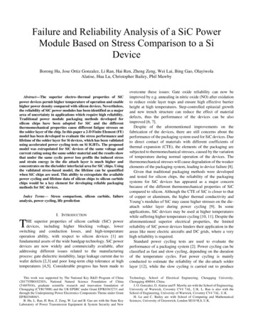
Approach/StrategyDislocation Defects in 4H‐SiC Commercial WafersOver the past decade there havebeen numerous publications(including NASA Glenn studies)linking degraded SiC power deviceperformance, yield, and reliabilityto the presence of dislocationdefects in the SiC wafer crystal.3‐inch diameter Cree wafer with epilayerMagnified view small area in middle of wafer‐ Each white dot or line is a dislocation defect!‐ Average defect density 104 per cm2Dislocation mapping images from Stahlbush et al, Mat. Sci. Forum vol. 556‐557, p. 295‐298 (2007)‐ Ultra‐Violet Photoluminescence Imaging (UVPL) dislocation imaging technique shown.National Aeronautics and Space Administration5
Approach/StrategyCommercial SiC Wafer Growth Approach(Sublimation growth or High Temperature CVD)C-axis (vertical) growth proceeds from topsurface of large-area seed crystal viathousands of screw dislocations.Vertical growth rate would not be commerciallyviable (i.e., would not be high enough) without highdensity ( 100 cm-2) of screw dislocations.Crystal enlargement is vertical (up c-axis).Negligible lateral enlargement.Thermal gradient driven growth at T 2200 CHigh thermal stress/strainFundamental Flaw: Abundant screw dislocation defects are needed for present SiCwafer growth approach, yet these same defects harm SiC power deviceyield and performance (cause blocking voltage de-rating, leakage, etc.).- High thermal stress also generates dislocations.National Aeronautics and Space Administration6
Approach/StrategyNew Approach - Large Tapered Crystal (LTC) Growth(US Patent 7,449,065 Owned by OAI, Sest, Inc., with NASA Rights)Vertical Growth Process:Fiber-like growth of smalldiameter columnar tip region(from single screw dislocation)Lateral Growth Process:CVD growth enlargementon sidewalls to producelarge-diameter boule(T 1500 - 2000 C)Small-diameter c-axis fiber fromsingle screw dislocation atmm/hour rate.MOST of crystal grown viaepitaxy process on laterallyexpanding taper atsignificantly lower growthtemperature (lower thermalstress) and growth rate.Completed boule sectionReady for slicing into wafersLarge diameter wafersyielded at mm/hour(wafers/hour) growth rate!Tapered portion is then re-loaded into growth system asseed for subsequent boule growth cycle.National Aeronautics and Space Administration7
Approach/StrategyLTC Vision: Dramatically improved SiC wafer qualityrealized at higher volumes and lower production cost.Present-Day SiC Wafer 1,000-10,000 screw dislocations/cm2 0.5 wafers per hourCost: 2000/4-inch waferCommercial Power DevicesLimited to 50-amp/die, 1 kVLTC SiC WaferIdeally 1 screw dislocation/cm2 1 wafer per hourCost: 500/6-inch waferCommercial Power Devices100-1000-amp/die, 10kVDrastic wafer improvement sufficient to unlock full SiC power device potential.(Approach also applicable to 3C-SiC, GaN, Diamond, and other semiconductors)However, LTC growth process is totally new and unproven. This work seeks toexperimentally investigate fundamental feasibility of LTC growth approach in SiC.National Aeronautics and Space Administration8
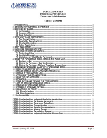
Approach/StrategyLarge Tapered Crystal (LTC) Growth MethodSimplified Schematic Cross-Sectional RepresentationFeatures (one embodiment):Tapered Crystal/BouleholderNo GrowthRegionNo. 3CompletedBouleFaceted taperedcrystalCrystal growth atmoderate growth ratein lateral (radial)directionTapered crystal/Boulemoves upwardcontinuouslyRegionNo. 2Fast laser-assistedfiber growth in the axial(c-axis) direction on acolumnar seed crystalLateral growthAxialgrowthRegionNo. 1National Aeronautics and Space AdministrationSmall-diameterColumnar seed crystal1. 3-Region growth apparatus for3 different growth actions.2. Region 1: Vertical (c-axis) growthon a very small diametercolumnar portion (“Fiber Growth”Year 2 Milestone).3. Region 2: Lateral (m-direction)growth on fiber & tapered portion(“Lateral Growth” Year 1 Milestone).4. Region 3: No growth after LTCboule reaches desired diameter.5. Growth rate of boule in caxis direction equals fastgrowth rate of columnarseed crystal.6. Boule contains only onedislocation along its axis; theremainder of the boule isnominally defect-free.9
Approach/StrategyComparison of LTC with Current State of the ArtLarge Tapered Crystal (LTC) SiCCurrent SiC Boule GrowthBoule thickness enlargement at mm/hourBoule thickness enlargement at mm/hourWafer contains only one threading screwdislocation (TSD)- Known location in middle of waferWafer contains many thousands of TSDs(100s to 10,000s per cm2 densities)- BPD multiplication via TSD climb [1]Boule grown via CVD epi at 1400-1900 C- Nearly isothermal deposition- Lower thermal stress(minimal stress-induced dislocations)Boule grown at 2200 C- Temperature gradient driven deposition- High thermal stress(abundant stress-induced dislocations)Wafer itself can serve as lightly-doped high-voltageblocking layer- Eliminates need for thick SiC epilayerWafer cannot be used as blocking layer- Thick SiC epilayer must be grown on top of wafer toprovide high-voltage blocking layerRapid wafer diameter up-scaling- Diameter set by growth system geometryWafer diameter up-scaling slower via repeatedprogressive seed crystal enlargement growthsNo waste from off-axis wafer cut(optimal wafer off-angles at no loss/cost)Part of boule wasted by off-axis wafer cut(% lost increases with diameter & off-angle)Isothermal holding chamber enables production ofmuch thicker SiC boulesReactor & source charge degradation, Tgradients/profile limit SiC boule thicknessHigher device performance and yieldDe-rated device performance and low yield[1] BPD Basal Plane Dislocation - See Chen et al., Mat. Res. Soc. Proc. vol. 911 p. 151 (2006)10National Aeronautics and Space Administration
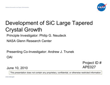
Approach/StrategyBuild on NASA Glenn pioneering expertise and facility for growing long ( 10 cm)high-quality single-crystal fibers via high temperature laser-assisted growth.- Decade of laser fiber-growth experience for variety of single-crystal oxides.- Modified argon-atmosphere chamber needed SiC growth of LTC fiber.NASA Glennlaser melt growthof single-crystalsapphire fiberfrom polycrystalsource feed rod.2 mmBuild on SiC melt solvent alloygrowth chemistries alreadydemonstrated for SiC growth.- Traveling Solvent (TS) [1]- Vapor-Liquid-Solid (VLS) [2]- Si, C, and solvent (Ge, Fe, Cr,etc.) provided in sourcematerial feed rod.Seed growth using small 4H-SiCmesa with screw dislocation.[1] L. Griffiths et al., J. Electrochem. Soc., 111, p.805 (1964).[2] W. Knippenberg et al., U.S. Patent 4,013,503,March 22, 1977.Figures from F. Ritzert & L. Westfall, NASA Technical Memorandum 4732 (1996).National Aeronautics and Space Administration11
MilestonesFirst SiC experimental demonstrations of the two critical growthactions required for Large Tapered Crystal (LTC) process. Year 1 (FY10 – “Lateral Growth”): Demonstrate epitaxial radialgrowth of a 5 mm diameter boule starting from a simulated SiCfiber crystal. Year 2 (FY11 – “Fiber Growth”): Demonstrate laser-assistedfiber growth of a SiC fiber crystal greater than 10 cm in length.LTC is NOT viable without success of BOTH milestones.Note that throughout this presentation, issues related to “LateralGrowth” milestone are highlighted in blue, while issues relating to“Fiber Growth” milestone are all highlighted in red.National Aeronautics and Space Administration12
Technical Accomplishments and ProgressMajority of progress since project funding initiated in December of2009 has been design and procurements for modification/buildup of laboratory hardware needed to initiate LTC experiments.andprocesses to be separatelyimplemented in this project, each in its own dedicated laboratory. “Lateral growth” to be carried out with modifications to existingSiC Growth Reactor #2 in NASA Glenn Aixtron Growth Systemin Building 77 Laboratory. “Fiber growth” to be carried out with build-up of newly-designedand dedicated SiC laser-growth chamber in existing NASAGlenn Laser-Assisted Fiber Growth Laboratory in Building 106.Project is new start (12/2009), so no previously reported accomplishmentsaside from patent, existing facilities and vast experience in technical field.Following poster panels give further non-proprietary information aboutwork in each lab. (Note that further details are contractor proprietary.)National Aeronautics and Space Administration13
Technical Accomplishments and ProgressLaser-Assisted SiC Fiber Growth Apparatus Design & BuildupComputer designdrawing of SiC fiberchamber with laser.CAD Drawing by Mark DieringerProcured components byCO2 laser for assembly.Details Majority of base component procurements complete – assembly to begin in spring after key deliveries. Ultra-high vacuum (UHV) chamber which can be evacuated to remove contaminates (e.g., O2 and H2O). Gas handling system to flow ultra-high purity Ar during growth. Growth process and data collection will be automated to precisely control and record conditions. Detailed imaging of hot zone. Precision fiber/seed positioning. ZnSe optics and windows will be used to handle the laser beam’s wavelength and power. High power CO2 laser has been serviced and ready for use – lab utility upgrades nearing completion.National Aeronautics and Space Administration14
Technical Accomplishments and ProgressSiC Epitaxy Laboratory Upgrades for “Lateral Growth” ExperimentsPreparations on-going for re-configuring SiC Epitaxy Reactor #2 for LTC work.- Conversion from cold-wall to hot-wall reactor configuration.- Conversion from full SiC wafer to SiC fiber sample mounting.- Procurements and machining work underway.Simulated SiC fiber seed crystals (cut from SiC boules) have been purchased and arebeing further prepared (etched & characterized) for upcoming lateral growth experiments.NASA Aixtron SiC Growth SystemNational Aeronautics and Space AdministrationNASA SiC Epitaxial Growth Reactor #215
Proposed Future Work Complete modifications of SiC epitaxial growth system tosupport radial (lateral) epi-growth of SiC fibers into boules. Carry out radial epitaxial growth of increasing diameter SiCboules starting from pseudo-fiber SiC seed crystals. Achieve5 mm diameter boule for Year 1 (FY10) Milestone. Complete procurement and build-up of laser-assisted SiC fibergrowth system and initiate first laser-assisted SiC fiber growthexperiments. Carry out seeded laser-assisted growth of SiC fiber crystals ofincreasing length and quality. Achieve 10 cm SiC fiber forYear 2 (FY11) Milestone. Carry out extended defect characterization of crystals. Thermal modeling support of experiments/setups.National Aeronautics and Space Administration16
Collaboration and Coordination withOther Institutions NASA Glenn Research Center (Prime – 2 Research Organizations) Sensors & Electronics Branch (RHS) – “Lateral Growth” Two decades of SiC epitaxial crystal growth experience. Ceramics Branch (RXC) – “Fiber Growth” Decade of laser-assisted ceramic fiber growth experience. Ohio Aerospace Institute (Non-Profit Research Contractor) Co-owner of core Large Tapered Crystal growth patent. Dedicated Technical Lead on SiC Epitaxy (RHS Laboratory). Sest, Inc. (Industry Contractor) Co-owner of core Large Tapered Crystal growth patent. SiC Crystal Characterization Lead, Thermal modeling. Oak Ridge Assoc. Universities (University Post-Doc. Contractor) Dedicated Technical Lead on Fiber Growth (RXC Laboratory).National Aeronautics and Space Administration17
Approach/Strategy(Beyond FY11)After LTC experimentally demonstrates viability, launch jointdevelopment of full prototype LTC SiC growth system (fibergrowth lateral growth) in collaboration with commercialand/or university development partners.Initiate basic GaN LTC experiments.Projected Go/No Go:- High growth rate of nearly defect-free boules- Commercial investment to develop mass production of largewafers.- Several companies interested IF feasibility demonstrated.National Aeronautics and Space Administration18
SummaryLarge Tapered Crystal (LTC) growth is a radically new (but experimentally unproven)game changing approach to SiC wafer growth offering the potential to drasticallylower material defects and cost that are presently major inhibitors preventing wideadoption of SiC high-power devices that would enable large improvements to EVpower converter size and efficiency.This recently-initiated NASA/DoE study is starting to carry out experimental proof-ofconcept of LTC growth with clear go/no-go for further investment/development.- Two years to modify NASA hardware and demonstrate two never-beforeexperimentally demonstrated “lateral” and “fiber” SiC growth processes.If successful, fully developed LTC wafer production would enable far superior EV powerelectronics with significantly improved efficiency and size.National Aeronautics and Space Administration19
NASA Glenn Research Center. Presenting Co-Investigator: Andrew J. Trunek. OAI. June 10, 2010. National Aeronautics and Space Administration. www.nasa.gov . Project ID # APE0