Transcription
NORTH CAROLINADEPARTMENT OF TRANSPORTATIONBorrow Pit Sampling ManualMaterials and Tests UnitField Operations Section
Borrow Pit SamplingFebruary 5, 2003Revised November 12, 2019North Carolina Department of TransportationMaterials and Tests Unit – Field Operations Section1
This page left blank intentionally.2
Table of ContentsSection 1 - Purpose 5Section 2 – Importance of Proper Sampling .5Section 3 – AASHTO Classification System 6Section 4 – Soil Terminology and Identification Properties .9Section 5 – General Sampling Procedures 11Section 6 – Sampling Procedures – Contractor 13Section 7 – Sampling Procedures – NCDOT 13Section 8 – Approving Borrow Source .14Appendix A – Borrow Material Criteria . .15Appendix B - Product Summary of Select Material and Shoulder / 16Slope MaterialAppendix C – Boring Log Example .24Appendix D – Sample Card Examples .28Appendix E – Soil Classification Test Report Examples .30Appendix F – HiCAMS data entry . .32Appendix G – Stockpile Sampling Procedures . 38Glossary 403
This page left blank intentionally.4
Section 1 - PurposeThe purpose of this manual, in conjunction with the class presentation and other relatedNCDOT reference manuals (described in Section 2), is to explain the techniques forobtaining soil samples from a proposed borrow pit or stockpile of existing soil. A borrowpit is generally utilized by the Contractor when a project requires a larger amount of fillmaterial versus amount of usable material obtained from cut sections. Additional fillmaterial which must meet other specification criteria may also be required for pipebackfill (i.e. Select Material). Due to various soil types in North Carolina, a fieldinvestigation must be performed to determine if the material meets minimum criteria foruse in a project. This field investigation must include documented observations from theborrow pit/stockpile and laboratory testing of soil samples obtained from the proposedsite. Borrow Material, Select Material – Class I, Class II Type 2, Class III Type 2 andShoulder/Slope Material must be naturally occurring soil (i.e. not from a manufacturingprocess) and tested for “Source Approval/Evaluation”. Appendix A provides a summaryof various select material products that may be used on a project. Soil sampling andrecorded observations completed during the field investigation of a proposed borrow pitor stockpile of material must be performed by project personnel having a valid BorrowPit Sampling Certification.Section 2 - Importance of Proper SamplingA sample is defined as a “portion, piece, or segment that is representative of a whole”. Itis therefore important that the procedure(s) used to obtain this small portion notcompromise the requirement that it be representative of the larger portion.As will be discussed in the sections that follow, each borrow pit sample will be taken to aNCDOT laboratory and tested for soil classification. The soil classification is utilized todetermine if the soil has the desired engineering properties (i.e. load-carrying capacity).Unsuitable soils placed in an embankment or subgrade may cause structural failure in theroadway leading to costly maintenance repairs; therefore, following proper samplingprocedures cannot be overemphasized. The NCDOT Construction Manual can provideguidance when sampling a proposed borrow pit or, during the construction phase, provideguidance when excavating soil from the pit. Project personnel should become familiarwith Divisions and/or Sections listed in Table 1.ClassificationMaterials (borrow sampling)Earthwork (borrow excavation)Reference DivisionDivision 10 (pages 10-21 thru 10-23)Division 5 Section 230Table 1 Reference sections from the NCDOT Construction Manual5
The NCDOT Standard Specifications for Roads and Structures (StandardSpecifications) can also provide guidance when sampling a proposed borrow pit/stockpileor, during the construction phase, provide guidance when excavating soil. Projectpersonnel should become familiar with sections listed in Table 2.ClassificationSelect MaterialBorrow MaterialShoulder and Slope MaterialBorrow ExcavationReference SectionSection 1016Section 1018Section 1019Section 230Table 2 Reference sections from the Standard SpecificationsProject personnel should also review all contract related documents including the ProjectSpecial Provisions for any items that may influence the sampling and/or excavation of aborrow pit or stockpile.Section 3 - AASHTO Classification SystemThe American Association of State Highway Transportation Officials (AASHTO) hasadopted a standardized method for determining soil classification or AASHTOclassification. Soils are grouped by the same general load-carrying capacity from the bestbeing A-1 to the worst being A-7. There is a wide range of load-carrying capacity withingroups and an overlapping of capacity between groups. For example, an A-2 soil maycontain material that makes it inferior to a specific A-5 soil. A Group Index number isused to designate the load-carrying capacity within the same AASHTO classification.For example, an A-4 (5) and A-4 (20) have the same AASHTO classification however;the group index number indicates that A-4 (5) has the greater load-carrying capacity.Several tests must be performed to determine AASHTO classification for a particularsoil.First, the overall distribution or “gradation” of particle sizes is analyzed by performingAASHTO T 88. For this AASHTO soil test, two different test methods must be utilized.The first method measures the distribution of coarse and fine sand by screening arepresentative sample over specific sieves to determine the percent passing each sieve.The second method measures the distribution of fine particles such as clay or silt by usinga hydrometer. The hydrometer test relies on the general concept of how quickly differentsoil particles settle when placed in a solution of water. For example, when soil is placedin a container with water and the mixture is agitated, the sand will settle to the bottom ofthe container first followed by the silt and finally the clay particles.The second step is to determine the Liquid Limit, Plastic Limit, and Plasticity Index.These tests are commonly referred as the Atterburg Limits of the soil. AASHTO T 89 isperformed to determine the Liquid Limit (L.L.) of the soil. The Liquid Limit is definedas the moisture content where the soil passes from the plastic state to the liquid state. Ahigh Liquid Limit indicates a high clay content and low load-carrying capacity.AASHTO T 90 is also performed to determine the Plastic Limit (P.L.) and the PlasticityIndex (P.I.) of a soil. The Plastic Limit is defined as the moisture content at which the6
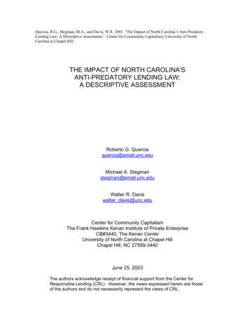
soil changes from a semisolid state to a plastic state. Load-carrying capacity of a soilincreases rapidly below the Plastic Limit and decreases rapidly above the Plastic Limit.The Plasticity Index is defined as the numerical difference between the Liquid Limit andthe Plastic Limit. Refer to the formula given below.P.I. L.L. – P.L.The general concept behind the Atterburg Limits tests relies on the reaction soil particleshave with water. Depending on the type and amount of particles in a given soil, differentstates of consistency will exist based on the amount of water within the soil. Forexample, “beach sand” generally has extremely small amounts of clay particles andtherefore would have a Plasticity Index (P.I.) of 0 or, what is commonly reported as,Non-Plastic (N.P.). Figure 1 graphically demonstrates these differences as water is addedor removed. Refer to the glossary provided in the back of this manual for definitions ofthe terms in Figure 1.LiquidStateAmount of waterLiquid limitPlasticStatePlastic limitSemisolidStateShrinkage limitSolidStateDryFigure 1 Summary – Characteristics of soil and water relationship7Liquid Limit minus the Plastic Limitequals Plasticity Index; equals range inmoisture content through which soil isplastic
Results from each AASHTO test are used to determine the soil classification. Table 3lists the main AASHTO groups, a general rating for use in subgrade, and a A-2-4A-2-5A-2-6A-2-7General DescriptionWell graded coarse to fine; non-plastic or feebly plastic; includes coarsewithout binderMostly stone fragments or gravelMostly coarse sand; may need added fines for a firm base; suitable or canbe made suitable for granular base coarseExcellentGranular with binder characteristics of A-4 and A-5 soilsExcellent toGoodGranular with binder characteristics of A-6 and A-7 soilsSoils are inferior to A-1 soils due to poor grading, inferior binder, or bothgenerally are suitable as a blanket for very plastic subgrades slated toreceive concrete pavementSands deficient in soil binder and coarse material; equigranular; examplesA-3Goodare fine beach or desert blown sands. Water has little effect on A-3 soilsComposed mostly of silt with only moderate to small amounts of coarseA-4Fairmaterial and only small amounts of clay; can vary texturally from sandyloams to silt to clay loamsSimilar to A-4 except that they include very poorly graded soils containingA-5Fairsuch things as mica; is a poor stability soil.Composed predominately of clay with moderate to negligible amounts ofcoarse material; have low stability at high moisture contents but are prettyA-6Fair to Poorstable otherwise; show shrinkage cracks during dry weather; is a good soilother than the fact that it has great affinity for waterComposed predominately of clay like A-6 but due to the presence of oneA-7Poorsize silt particles, organic matter, mica flakes, or lime carbonate, is elasticModerate plasticity indexes; may be highly elastic. P.I. less than or equalA-7-5Poorto L.L. –30A-7-6PoorHigh plasticity indexes P.I. greater than L.L. –30Table 3 Summary of AASHTO Classifications (subgrade rating and general description)A-2Good8
Section 4 - Soil Terminology and Identification PropertiesWhen sampling a borrow pit or existing stockpile, a boring log must be completed with adescription of the material encountered. To aid in completing a general description for aboring log, refer to the general terms and definitions provided in Table 4.TermsDefinitionA rock fragment, usually rounded by weathering or abrasion, with average dimensionBoulderof 12 inches or moreA rock fragment, usually rounded by weathering or abrasion, with average dimensionCobblebetween 3 to 12 inchesRounded, sub-rounded, or angular particles of rock that will pass a 3-inch squareGravelopening sieve and be retained on a Number 4 Sieve.SandParticles that will pass the Number 4 Sieve and be retained on the Number 200 SieveMaterial passing the Number 200 Sieve that is non-plastic and exhibits little or noSiltstrength when driedMaterial passing the Number 200 Sieve that can be made to exhibit plasticity within aClaywide range of water contents and exhibits considerable dry strengthFinesThe portion of a soil sample passing a Number 200 SieveMarlUnconsolidated white or dark gray calcium carbonate depositMuckFinely divided organic material containing various amounts of mineral soilPeatOrganic material in various stages of decompositionOrganic ClayClay containing microscopic size organic matterOrganic SiltSilt containing microscopic size organic matterCoarse-Grained Soil Soil having a predominance of gravel and/or sandFine-Grained SoilSoil having a predominance of silt and/or clayMixed-Grained SoilSoil having significant proportions of both fine and coarse grained soil particlesTable 4 Soil terminology and description9
Table 5 provides methods for identifying items encountered while performing the ClayMarlMuckPeatOrganicClayOrganicSiltMethod of IdentificationIdentify by particle sizeIdentify by particle sizeIdentify by particle size.Identify by particle size. Gritty grains that can easily be seen and felt. No plasticity orcohesion. Size ranges between gravel and silt.Identify by behavior. Fines that have no plasticity. May be rolled into a thread but willeasily crumble. Has no cohesion. When dry, can be easily broken by hand into powderyform.Material passing the Number 200 Sieve that can be made to exhibit plasticity within a widerange of water contents and exhibits considerable dry strength.A white or gray calcium carbonate paste. May contain granular spheres, shells, organicmaterial or inorganic soils.Black or dark brown finely divided organic material mixed with various proportions of sand,silt, and clay. May contain minor amounts of fibrous materials such as roots, leaves, andsedges.Black or dark brown plant remains. The visible plant remains range from coarse fibers tofinely divided organic material.Dark gray clay with microscopic size organic material dispersed throughout. May containshell and/or fibers. Has weak structure which exhibits little resistance to kneading.Silt containing microscopic size organic matter.Man-made deposits of natural soils and/or waste materials. If encountered, documentcomponents carefully.Table 5 Summary of identification methods for types of soilFillThe following steps can be followed in identifying a soil encountered during the fieldinvestigation:Step 1 - Decide if soil sample is coarse-grained, fine-grained, mix-grained ororganic. If mix-grained, decide whether coarse-grained or fine-grainedpredominates and record conclusionStep 2 – Determine principal or primary component. Use noun in soil description(i.e. Sand).Step 3 – Determine secondary component. Use adjective in soil description (i.e.Silty Sand).Step 4 – Determine if additional components exist. Use as additional adjectives(i.e. Silty Sand, Gravelly) and record conclusionSome typical examples of soil component descriptions include: Silty Fine Sand, GravellySand, Clayey Gravel, Clayey Silt, Silty Clay, etc.10
Table 6 lists additional information which should be documented on the boring log.ItemColor of sampleMoisture ConditionDescriptionsBrown, Gray, Red, Black, etc.Dry, Moist, Wet Judge by appearance as the material is initially removedPlastic, Low Plastic, Non-plastic. Sample must be in moist or wetPlasticitycondition for plasticity determination.Table 6 Additional descriptive information for field investigationThe data obtained from the field investigation and the GeoMaterials Laboratory testresults will serve to establish a soil profile of the borrow pit. The soil profile is thevertical cross-section composed of three major layers designated as A, B, and C-horizons.Horizon A: basically topsoil containing organic matter except for possibly thebottom part of the layerHorizon B: the subsoilHorizon C: the mother soilThe usable soil can primarily be found in the B-horizon however, the lowest portion ofthe A-horizon and the top part of the C-horizon may also contain usable material.Section 5 – General Sampling ProceduresWhen sampling a borrow pit/stockpile, the Contractor or NCDOT may provideequipment and personnel for obtaining soil samples. The sampling procedures outlinedbelow shall apply to either the Contractor or NCDOT. When sampling from an existingstockpile, follow procedures provided in Appendix F of this manual1. Prior to performing any sampling, the Contractor shall furnish the ResidentEngineer with a dimensioned plot plan of the proposed site to a scale such thatit can be placed on 8 ½” X 11” or 11” X 17” sheet. The Contractor shall alsoprovide a release from the property owner allowing access to the property andthe right to obtain samples from the property.2. Samples shall be obtained by the use of hand auger or power flight auger.Other equipment such as a dragline or backhoe may be used if approved bythe Engineer.3. Samples shall be obtained by the Resident Engineer or his/her representativewith a valid Borrow Pit Sampling Certification4. Each sample shall consist of 5 to 8 pounds of soil (fill sample bag one quarterfull). Place a completed sample card (refer to Appendix C) in each bag.11
5. A minimum of two (2) test borings per acre will be required. The minimumnumber shall be increased if determined necessary in order to obtainrepresentative samples for the entire source.6. Each test boring shall be identified by a stake driven adjacent to the testboring hole. The test boring number shall be shown on the stake.7. Within each bore site samples will be acquired from any significantlydifferent layer of soil. Combining materials from different layers into acomposite sample will not be permitted.8. Each test boring shall be designated numerically (S-1, S-2, S-3, etc.) in theorder of drilling.9. The first sample from a test boring shall be identified by the test boringnumber. Any additional samples from a test boring shall be identified by thetest boring number plus an alphabetical letter (S-1, S-1A, S-1B, etc.) Theseadditional samples shall be designated alphabetically in order from the surfacedown.10. If the same soil type exists between multiple bore sites the sample can bereferenced to the original soil sample. For example, if bore location number 3from 0 – 2 feet in depth contains the same soil as encountered at bore locationnumber 1 (0 - 2 feet) then an entry can be made on the boring log to referencesoil at site #3 back to S-1 (i.e. R S-1). Therefore, no sample would berequired from bore location number 3 from 0 – 2 feet in depth. Referencingsoils should only be completed when the individual is confident that thematerial is the same (if in doubt take a sample). Refer to Appendix B for aboring log example.11. A boring log shall be kept of each test boring and will show the following:a.b.c.d.e.f.Test boring numberVisual description of the material encounteredElevation or depth below surface of layer of material encounteredLocation of samples obtainedLocation of water tableTotal depth of boring12. For each source, a site map shall be prepared showing the following:a. The location of the source in relation to natural landmarks, property linesand/or existing public roads in the area.b. A plan view of the property and all test borings with identifying numberslabeled12
Section 6 - Sampling Procedures – ContractorIf the Contractor provides resources used in obtaining samples, the following procedureswill apply in addition to the procedures listed in the previous section.1. The Contractor shall furnish all sampling equipment and competent personnelto operate the equipment.2. A Division of Highways representative with a valid Borrow Pit SamplingCertification shall determine the frequency and location of all test borings.3. All samples will be taken according to Section 5 of this manual in thepresence of the Resident Engineer or his/her Borrow Pit Sampling Certifiedrepresentative.4. The Resident Engineer shall be responsible for ensuring that sufficient testborings are made and samples taken are representative of the proposed source.5. The Contractor will be responsible for marking and placing an identifyingstake at each boring site.6. The Division of Highways representative shall transport all samples to aMaterials and Test Unit laboratory. The Contractor shall not deliver anysamples for testing. The Division of Highways will be responsible for anysoil treatment necessary because of quarantine regulations of the U. S. and/orN.C. Department of Agriculture.7. The Division of Highways representative shall maintain the boring log andprepare the site map. Upon completion of the investigation, one (1) copy ofeach will be transmitted to the Materials and Tests Unit.Section 7 – Sampling Procedures – NCDOTIf the Department provides resources to obtain samples, the following procedures willapply in addition to the procedures listed in the general sampling section.1. The Contractor’s request for Department to perform the sampling shall besubmitted to the Resident Engineer in writing.2. The Resident Engineer will forward the request and the other required data tothe Geotechnical Engineering Unit.3. The Geotechnical Engineering Unit, prior to performing any sampling, willcontact the Resident Engineer to determine if he/she desires that projectpersonnel be present.13
4. The Geotechnical Engineering Unit will obtain the samples in accordance toSection 5 of this manual and transport them to a Materials and Tests Unitlaboratory for testing.5. The Geotechnical Engineering Unit will be responsible for marking andplacing an identifying stake at each boring site.6. The Geotechnical Engineering Unit will be responsible for any soil treatmentnecessary due to quarantine regulations of the U. S. and/or N. C. Departmentof Agriculture.7. The Geotechnical Engineering Unit will be responsible for submitting costdata to the Finance Department for invoicing the Contractor.Section 8 – Approving Borrow SourceThe Materials and Tests Unit will submit copies of all test reports to the ResidentEngineer for analysis. The Resident Engineer, utilizing the appropriate section(s) of theStandard Specifications, will analyze the test results, boring logs, and site map todetermine the acceptability of the source. The Resident Engineer will also consider anyapplicable project special provisions as the basis for making the determination. TheGeotechnical Engineering Unit, if requested, will assist the Resident Engineer inevaluating the material. The Resident Engineer will advise the Contractor in writing thefollowing issues:1. The limits of acceptable material.2. If special handling of the material is necessary.3. Approval of the source for borrow material is based on the limited samplingand test results of the samples submitted. Therefore, such approval is with theunderstanding that the Division of Highways reserves the right to use visualinspection and additional sampling on the roadway, as deemed appropriate bythe Engineer, to reject any unsuitable material encountered. The rejectionmay occur regardless of whether or not such material was indicated asacceptable during initial borrow pit sampling.4. Where deemed appropriate, the Resident Engineer will designate how thematerial is to be removed from the pit and also where to isolate areas or layersof unsuitable material in the pit.5. Any material found on the roadway that fails to meet the acceptabilityrequirements, shall be removed and replaced with acceptable material at nocost to the Department.14
Appendix ABorrow Material CriteriaThe following information taken from Section 1018 of the Standard Specifications is provided inthis manual for instructional purposes only. Use the latest edition of the Standard Specificationsand/or appropriate Project Special Provisions when evaluating borrow material.Statewide Criteria for Acceptance Borrow MaterialUse only natural earth material. Any other materials are subject to rejection.Piedmont and Western Area Criteria for Acceptance of Borrow MaterialSoil with PI of 25 or lessAcceptableAcceptable, but not to be used in top 3 feet ofSoil with PI 26 through 35embankment or backfillSoil with PI of more than 35Not AcceptableTable 6 Piedmont and Western Criteria for Acceptance of Borrow MaterialExceptions to Statewide Criteria for Acceptance of Borrow Material1) Soils in the Coastal Plain (area described below) will be accepted in accordance withthe following table.Coastal Area Criteria for Acceptance of Borrow MaterialSoil with PI of 15 or lessAcceptableAcceptable, but not to be used in top 3 feet ofSoil with PI 16 through 20embankment or backfillSoil with PI of more than 20Not AcceptableTable 7 Coastal Area Criteria for Acceptance of Borrow MaterialAreas where Coastal criteria are applicable are as follows:Division 1 – Entire Division except Northampton (West of I-95)Division 2 – Entire DivisionDivision 3 – Entire DivisionDivision 4 – Edgecombe, Wayne, Johnston, (East of US 301), Wilson (East of I-95),Nash (East of I-95), Halifax (East of I-95)Division 6 – Bladen, Columbus, Robeson, Cumberland, Harnett, (South of NC 27)Division 8 – Scotland, Hoke, Moore, (Southeast of US 15-501, NC 73, NC 211),Richmond (East of US 220 North and US 1 South)The Coastal criteria shall be applicable to the flood plains of the Roanoke, Tar, Neuse, Cape Fearand Lumber Rivers and their tributaries that are outside the above described areas.2) Waste or by-products from industrial processes or mining operations are notacceptable except by specific written approval.3) When tested, soils having a pH of less than 5.5 or an organic content more than 4.0%may be rejected.4) When material is to be used for placing embankment or backfilling of undercut areasthat are excessively wet, the material shall consist of Class II, III, or IV selectmaterial.15
Appendix BProduct Summary of Select Material and Shoulder / Slope MaterialRefer to Section 1016 of the Standard Specifications for additional information16
17
18
19
20
21
22
23
Appendix CBoring Log Example and Blank Boring Log Sheets24
25
26
27
Appendix DSample Card ExamplesThe following sample card examples represent typical borrow samples obtained from apit. Note the samples in this example are to be checked for borrow source approval andSelect Material Class II Type 2 source approval. Sample cards shall be legible andcompleted with all required information.28
29
Appendix ESoil Classification Test Report ExamplesUsing test reports, appropriate sections of the Standard Specifications, and the BoringLog, establish a soil profile of the proposed pit. Designate sections of the pit where soilmay not be acceptable or have restricted uses (i.e. not to be used in top 2 feet ofembankment). Refer to Section 8 in this manual for additional information.30
31
Appendix FThis appendix summarizes the steps for entering borrow pit soil samples into HiCAMS.If the technician sampling a proposed borrow pit does not have an active Borrow PitSampling Certification the sample will not count towards the minimum samplingfrequency as required by the Minimum Sampling Guide. Any samples obtained by atechnician without a valid certification will be used for information only. For thisexample, the sample was obtained for a construction project in the Cumberland Countyarea.Step 1 Select Sample Details windowStep 2 Enter “Sampled Date:”32
Step 3 Enter information prompted by the next screen.Step 4 After information has been entered select “Retrieve” and then select “OK”33
Step 5 Enter sample information within the “General” tabStep 634
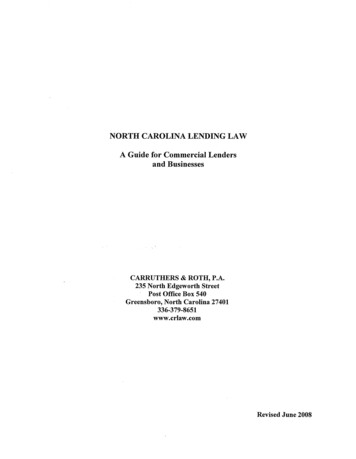
Step 7 Select the “Cont/Loc” tab and enter sample informationStep 8 Note: this project has more than one borrow pit as indicated in the “Location”entry window. The approximate depth from which the soil sample was obtained is alsolisted in the “Location” window. If station(s) are provided, enter into “Station” windows.“Coastal Plain” is checked due to Cumberland County falling within the coastal plaincriteria requirements. Refer to Section 1018 Borrow Material in the StandardSpecifications to determine if the proposed borrow pit meets statewide or coastal plaincriteria.35
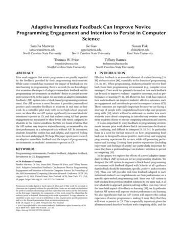
Step 9 Select the “Tracking” tab and enter sample informationStep 10 Enter sample information and select the save button. Record the “Sample ID” inthe top right box of the sample card (labeled “HICAMS #:”).36
Since the HiCAMs database is changed periodically, personnel responsible for enteringdata into the system should monitor the Construction Unit’s website for updates.HiCAMs Information37
Appendix GThis appendix describes sampling procedures when obtaining soil samples from astockpile. Samples are to be tested for “Source Approval/Evaluation”. Utilize plans,Standard Specifications or appropriate Project Special Provisions to determine whichminimum criteria the soil must meet. Indicate on each sample card which criteria thesample should be checked against (i.e. Class I, Class II Type 2, etc.) Additionalinformation regarding select material is provided in Appendix A.If the material to be sampled has been stockpiled, a wheeled or tracked loader unit shouldbe used to obtain representative samples. The equipment and procedures for obtaining asample are as follows:Equipment1.2.3.4.5.6.7.Flat shovelLarge scoopSample bags (in good condition)Plastic tiesSample cardsPlastic bags (for sample cards)Boring log sheetProcedures1. A minimum of three samples should be taken from three different locationsaround the stockpile2. The loader unit should approach the pile with the bucket as low as possible3. While moving forward push the bucket into the pile and lift the bucket up throughthe pile4. This first bucket of material is placed to the side5. Repeat steps 2 and 3 at the same location and obtain one full loader bucket ofmaterial6. Dump the material and, using the loader unit, strike off the top half of the conicalshaped pile7. Using a flat shovel divide the flat surface of the struck off pile into four quadrantsby scribing a “plus“sign.8. Designate the quadrants as “A” , “B”, “C” and “D”9. Obtain one large scoop or shovel full of material from two opposing quadrants(i.e. A and D or B and C)10. Repeat steps 2 through 10 at opposing locations around the stockpile for theremaining two samples11. If needed, additional samples may be taken (especially if the material within thepile varies)12. Complete a sample card for each bag (note on the sample card which criteria tocheck sample against i.e. Class I, Class II - Type 2, etc.)13. Place each sample card in a plastic bag38
14. Place a completed sample card in each bag15. Complete boring log and include a sketch of stockpile along with approximatesample locations16. Submit samples to the GeoMaterials Laboratory17. As soil is excavated from the stockpi
These tests are commonly referred as the Atterburg Limits of the soil. AASHTO T 89 is performed to determine the Liquid Limit (L.L.) of the soil. The Liquid Limit is defined as the moisture content where the soil passes from the plastic state to the liquid state. A high Liquid Limit indicates a high clay content and low load-carrying capacity.