Transcription
OPERATION & INSTRUCTION MANUAL(3kW – 12kW Steam Generator & Control Panel)
Table of ContentsPart 1: Steam GeneratorSafety Warnings Safety Warnings in French Users Instructions .Choosing a proper location . .Steam equipment installation diagram .Installation of the pipeline .Steam Generator blueprint .Electric requirements .Power line assemble illustration Wiring Diagram 380-415V (3PH) Wiring Diagram 208V (3PH) .Wiring Diagram 220-240V (1PH/2PH) . .Installation of the top light .Choose your type of machine .Steam generator configuration . Troubleshooting guide . Specification .234455810111213141516171819Part 2: Control PanelControl Panel blueprintController Installation instructionTemperature detector installationController Panel IllustrationOperating instructions2021222223 . . . . . ***SAVE THESE INSTRUCTIONS!READ AND FOLLOW ALL INSTRUCTIONS.***Ces instructions sont à conserver soigneusement!ETUDIER ET ENSUITE SE CONFORMER À TOUTES LESINSTRUCTIONS-1-
WARNING!To reduce the risk of injury, do not permit children to use this product unless they are closely supervised at all times.WARNING!To reduce the risk of injury:a. The wet surfaces of steam enclosures may be slippery. Use care when entering or leaving.b. The steam head is hot. Do not touch the steam head and avoid the steam near the steam head.c. Prolonged use of the steam system can raise excessively the internal human body temperature and impairthe body’s ability to regulate its internal temperature (hyperthermia).WARNING!Hyperthermia occurs when the internal temperature of the body reaches a level several degrees above the normalbody temperature of 98.6 F. The symptoms of hyperthermia include an increase in the internal temperature of thebody, dizziness, lethargy, drowsiness, and fainting. The effects of hyperthermia include:a) Failure to perceive heat;b) Failure to recognize the need to exit the steam bath;c) Unawareness of impending risk;d) Fetal damage in pregnant women;e) Physical inability to exit the steam bath; andf) Unconsciousness.WARNING!The use of alcohol, drugs, or medication can greatly increase the risk of hyperthermia.Limit your use of steam to 10 – 15 minutes until you are certain of your body’s reaction.Excessive temperatures have a high potential for causing fetal damage during the early months of pregnancy.Pregnant or possibly pregnant women should consult a physician regarding correct exposure.Caution: Do not place wire in close proximity to hot water or steam pipes.Attention: If the installation and operation instruction are not read or understood, do not install. Install the controllerbased on the installation instruction.If the controller is installed outside the steam room, the temperature sensor must be installed in the steam room. Toprevent overheating, operate the controller as described in this manual only.**Not for Space Heating Purposes-2-
DANGER!Afin de réduire les risque de blessures, ne jamais autoriser des enfants à utiliser ce appariel, sauf s’ils sont étroitement surveillés, àtout momentDANGER!a) Les cabines où de la vapeur est introduite peuvent comporter des surfaces humides et donc glissantes. La plus grandeprudence est de rigueur au moment où l’utilisateur pénêtre, ou quitte la cabineb) La tête d’injection de la vapeur est à haute temperature; il faut veiller à ne pas entrer en contact avec cette têted’injection. De plus, il faudra éviter le contact avec le jet de vapeur à proximité de la tête d’injection.c) Soumis, d’une maniére prolongée aux températures occasionnées par un jet de vapeur, la température interne du corpshumain est susceptible de dépasser le seuil où celui-ci s’auto-régule, provoquant l’hyperthermie.DANGER!Le corps humain enter en hyperthermie quand sa température interne dépasse de plusieurs degrés sa temperature normale de 98.6ºFahrenheit, soit 37 Celsius.La personne en état d’ hyperthermie souffre d’étourdissements, est léthargique, assoupie et susceptible d’évanouissement.Les effets de l’hyperthermie comportent:a) Insensibilation à la chaleurb) L’absence de volonté de quitter le local sous temperature élevéec) Inconscience du danger imminentd) En ce qui concerne les femmes enceintes, la possibilté de réactions nocives au niveau du fétus. Les femmes enceintes,ou potentiellement enceintes, doivent préalablement consulter un médecine) Engourdissement physique menant à l’incapacité de quitter le localf) Perte de connaissanceDANGER!L’usage de drogues, d’alcool, de médicamments est susceptible d’augmentrer les risques d’hyperthermie dans de largesproportions.Avant utilization, il y a lieu de limiter votre usage de la vapeur à 10-15 minutes pour tester les réactions de votre corps.Pendant les premiers mois de grosses, des températures excessives sont susceptibles d'engendrer des dommages, à issue fatale,au fétus. Les personnes enceintes, ou probablement enceintes, doivent obtenir un avis médical en ce qui concerne lesconditions auxquelles elles peuvent se soumettre.Avertissements Ne pas installer de fils à proximité d’eau chaude ou de conduits de vapeurLa tête d’injection de vapeur ainsi que l’orifice de débit de vapeur sont à hautes températures – Eviter le contact de ces appareilssous peine de brulûres.Cet appareil ne doit pas être utilisé à de fins de chauffage ambiantAvant toutes opérations de maintenance et de nettoyage, déconnecter la source de courantInstallation Installer la tête d’injection de vapeur enter 15 et 30 cm au-dessus du sol. Si le bain de vapeur se trouve dans la baignoire ou la sallede bains, installer la tête d’injection de vapeur à 15 cm au-dessus de la baignoireLe jet de vapeur doit être dirigé vers le bas. Entourer le filet du tuyau de vapeur de quelques couches de Teflon, visser la têted’injection de vapeur et visser manuellement.-3-
Part 1: Steam GeneratorUser instructionsAttention: We are not responsible for the malfunction and damage from improper installation that does not comply with the user’s manual.1.2.3.4.5.6.Make sure the model and the accessories are correct, including the voltage input.Make sure the steam power is matched with the dimensions of the sauna room. Pay attention to the steam room's cubic feetmeasurements and construction materials. If you have any problems, please refer to the Page 11 to get the correct information.Make sure to read this manual carefully for correct and effective use.We shall not be responsible for the product damage or malfunction caused by self-installation or the operation procedures which isnot in compliance with the Operation and Instruction Manual.Please check the contents when the package arrives to assure it is in good condition. If you find any damage in the package,please contact the transportation company or the supplier to claim any damage.This product must be used indoors.Choosing proper locationRecommended locations for proper installation:1. The steam box should not be located further than 16 feet away from the steam room.2. The steam generator should not be installed in the steam room.3. The steam generator should not installed outdoor or in any places that will influence the security of the machine.4. Do not install it in any places where the water might freeze.5. Do not install near flammable objects or chemicals (coal, gas, etc.)6. The steam generator should be installed in a dry and ventilated place.7. Make sure the steam generator is secured on the wall and is in horizontally positioned.8. On the other three sides, there has to be minimum of 12inces of space left between steam generator and any other object.9. The place where the machine is installed must be accessible for cleaning and possible service work.10. The steam generator should be in a close proximity to a drain for convenient Water Drain Valve hook-up.11. After use, the steam pipe, safety valve, drain valve, water pipe, steam outlet is still very hot.12. Place steam outlet away from bathers.Attention: install an exhaust fan outside of the steam room so that it can expel any excess steam for proper ventilation.-4-
Attention: The steam generator (including the controller) are UL approved.Installation drawing of the steam generator!A tten tion : T h e d r a w i n g is o n lyfo r ex pla n a tio n .F or p r ac tic a l de s ig n o f s te amr o o m ,p le a s equ al ifie dC o n tr o l p an elc o n su ltd e s ig n e r,w ithar c h i te cto r b u il d e r.S u p p lyS te a mo u tle tp ip eP r e s s u r e r e lie f v a lv eW a te r I n le t P ip eS te a m g e n e r a to rW a te r D r a in Va lv eS team O u tletInstallation of pipelineAttention: The installation of all the pipes should be completed by qualified plumbers or technicians.1.2.Use brass or copper pipes only.Do not use black, galvanized or PVC pipes.Water supply pipe (1/2'')1. Connect cold water pipe to water inlet.2. Install shutoff valve in the water supply pipe. The shutoff valve should be installed in a place where it is easily operated in case ofemergency.3. Clean the water supply pipe completely before connecting it to the steam engine.4. It is suggested that a water filter should be installed in the water supply pipe.5. The water pressure should be no less than 20 pounds/square inch (psi), and no more than 75 (psi). If necessary, decrease orincrease the pressure accordingly.-5-
Steam pipe (3kW/4.5kW pipe size: 1/2'' 6kw & above:3/4'')1. Do not install any valves in the steam pipes. The steam can never be obstructed.2. Install a brass or copper steam pipe(3kW/4.5kW pipe size: 1/2'' 6kw & above:3/4'') as connector between the steam outlet and thesteam nozzle.3. The heat insulation material used to insulate the steam pipe should be resistant to temperature as high as 248oF or higher.4. Do not bend the pipe so that the cooled water will not stay in the curve of the steam pipe.5. The shorter the steam pipe, the better. Try to decrease the number of elbows and avoid abrupt turns.6. Have no valleys or dips in the output steam line.7. Do not install a valve in the steam line.8. Do not connect the drain valve into the steam line.9. Do not connect the over-pressure device output into the steam line.Steam nozzle (3kW/4.5kW pipe size: 1/2'' 6kw & above:3/4'')WARNING!The steam nozzle and steam outlet are very hot! Avoid installing the steam nozzle near steam bathers.1. Install the steam nozzle 6-12 inches above the ground. If the steam bath is in the bathtub orbathroom, install the steam nozzle 6 inches above the bathtub.2. The steam spray outlet should be installed face down. Wrap a few circles Teflon tape around thethreads of the steam pipe, install the steam nozzle and tighten with hands.DANGER!1. Installer la tête d’injection de vapeur enter 15 et 30 cm au-dessus du sol. Si le bain de vapeur setrouve dans la baignoire ou la salle de bains, installer la tête d’injection de vapeur à 15 cm audessus de la baignoire2. Le jet de vapeur doit être dirigé vers le bas. Entourer le filet du tuyau de vapeur de quelquescouches de Teflon, visser la tête d’injection de vapeur et visser manuellementAttention: In order to protect the steam nozzle, do not use any tools to tighten that will scratch finish, use a little soap water and soft spongeto wipe, and do not use erosive chemical solutions or abrasive cleaning tools.-6-
Attention:Please consult your distributors of building materials like acrylic, fiber glass or other heat resistant sheet about the installation andposition of steam nozzle. It is suggested that MS-103412 heat resistant material is used.IfA i rp ro o f g re e n m a t e ri a l b e l tnon-heat-resistanta c ry l i cisre se rv eausedgapasnom aterialbuildingsm allerlikem a t e ri a l ,than1 / 4 ''a n d fi l l w i t h h e a t -i n su l a t e d m a t e ri a l .U sea irproofsilic onc o r r e s p o n d i n gm a t e ri a ltofi l lthetoachievew allinge lora i r p r o o fthethegapsinw a t e r-In si d e w a l l o f t h e st e a m ro o mp ro o f a n d d a m p -p ro o f e ffe c t .Drainpipe (1/2'')According to national and local codes, the steam engine drain valve should be equipped with drainpipe. The steam engine will drain water onits own.Attention: drainpipe should not incline upwards.Safety valve1. Safety valve is to prevent too much steam pressure in the interior steam engine.2. The pressure limit range of safety valve is 15PSI and the pressure will begin to decrease if pressure should come over this value.3. Provide the safety valve with exterior drainpipe.Attention:1. For safety, do not dismantle the pressure decrease valve at random.2. To maintain the proper and automatic operation of safety valve, make sure the safety valve connection pipe is smooth.-7-
Blueprint for the steam engine395mm304mm142mm43mm266mm32mm151m mWater inlet188mm206mmSafety valveWaterdrainage72mmFuse for wire power supplyCon troller wireand light wire holePower wire holeFuse for wirepower supplySteam outlet370mmSafetyvalve180mm260mmWater i nl etWater drainage400mm100mm160mmFuse for w ire power supplyC on t rol l er w i rea nd li ght w ir eholePower wi re holeFuse for wirepower supply-8-302mmSteam outlet
535mm435mm234mmSteam outlet350mm385mmSafety valve34mm273mm183mmWater inletWaterdrainageFuse for wire power supplyCon troller wireand light wire holePower wire holeFuse for wirepower supplyAttention: Keep the steam engine clean.Attention: To avoid damage to the equipment, do not connect strong electrical current directly to the components.IMPORTANT: Each unit shall be provided with a pressure-release device to address overpressure due to inadvertent blockage of the outputsteam head or piping. If factory installed, it shall be provided with no more than 6 inches (150mm) of piping between the device and thegenerator tank. If shipped with the steam generator, the installation instructions shall indicate it shall be installed to the generator tank with nomore than 6 inches (150 mm) of piping.-9-
Electrical requirements:Electricity supply circuitry:1. Test the voltage of the electric supply and make sure that the steam engine with suitable electric voltage is used.2. Insulated copper wire should be used with a heat resistant temperature of 194oF and a specified voltage of 500V. Refer to nationalor local electricity consumption code for the specifications. Refer to the ammeter for the ampere.3. Choose steam engine with suitable item number, and plug the ground wire into the ground terminal.4. Install an independent GFCI circuit breaker between the power supply and the steam engine so as to provide an electric supplywith overflow protection and electricity leakage protection.Important: All the connections must be in accordance with national and local electricity code and be installed by professional electricians.Ampere MeterTypeGS08-6kWGS08-9kWApplicable space of theroom (m3)5 810 12Electricity supply27.3A10# or 6.0mm2208V / (3PH)16.7A12# or 4.0mm2380-415V / (3PH)9A12# or 2.0mm2220-240V / (1PH/2PH)41A8# or 8.0mm2208V / (3PH)25A12# or 4.0mm213.7A12# or 2.0mm255A6# or 10.0mm2208V / (3PH)33.3A8# or 6.0mm2380-415V / (3PH)18.2A12# or 4.0mm2220-240V / (1PH/2PH)14 16Specifications for powerwire ( A W G)220-240V / (1PH/2PH)380-415V / (3PH)GS08-12kWMax. Electricalcurrent (A)The data provided above are for 220-240V (1PH/2PH) and 208V (3PH) and 380-415V (3PH).- 10 -
Assembly graph for power wireAttention: To avoid the damage to the equipment, do not connect strong electric current to the component directly.WARNING!This graph is for explanation only. For actual installation, refer to national and local electric codes and consult with a professional electrician.Power connection terminal(3-12k W)(6-18k W)(220-240V 2PH)(208V 3PH)Power connection terminal(3-12k W)(220-240V 1PH)Power connection terminal(6-9kW)(380-415V 3PH)- 11 -(10.5-18kW)(380-415V 3PH)
Wiring Diagram 380-415V (3PH)S u p p lyNW a te r L e v e l S e n so rL3L2L1GT o C o n t ro l P a n a lR e d ( S h o r t P in )B la c k ( L o n g P in )T e rm i n a l B l o c kRe d J1-2 RedRedRe d J2-2 RedBlackJ2R edR e dB ro w nR e dB la c kRedB lueL ig h tRedB la c kRe dDrain water valveYe llowSRedRedFill water valveRedSY e l l o w / G re e nBlack J1-1 BlackB lackRed J2-1P in )J1Ye llo w ( M id d leRedG S 08-6kW /7.5kW /9kW (380-415V 3P H )S u p p lyNL3L2L1GW a te r L e v e l S e n so rT o C o n t ro l P a n a lR e d ( S h o r t P in )T e rm i n a l B l o c kB la c k ( L o n g P in )Ye llo w ( M id d leP in )Red J1-2 RedBlackJ2R edRed J2-2 RedR e dRedDrain water valveYellowSR e dRed J2-1Fill water valveSBlack J1-1 BlackJ1Y e l l o w / G re e nB lackR e dRedB ro w nB la c kRedR e dRedB lueL ig h tRedB la c kR e dG S 0 8 - 1 0 .5 k W / 1 2 k W / 1 3 . 5 k W ( 3 8 0 - 4 1 5 V 3 P H )S u p p lyW a te r L e v e l S e n so rT o C o n t ro l P a n a lR e d ( S h o r t P in )N L3 L2 L1GT e rm i n a l B l o c kB la c k ( L o n g P in )P in )J1Y e l l o w / G re e nB lueR e dB ro w nR e dL ig h tR e dB la c kG S 08-15kW /18kW (380-415V 3P H )- 12 -J1-2J2-1J2-2J3-1J3-2J2J3B la c kRed RedSR edB lackRedDrain water valveSR e dRedFill water valveR e dYellowB lackJ1-1Ye llo w ( M id d le
Wiring Diagram 208V (3PH)S u p p lyW a te r L e v e l S e n so rL3 L2T o C o n t ro l P a n a lL1GR e d ( S h o r t P in )T e rm i n a l B l o c kYe llo w ( M id d leJ1B la c k ( L o n g P in )P in )Y e l l o w / G re e nDrain water valveYellowB lackSR e dJ3-2J2-1J3-1J1-2J1-1J2-2RedB la c kRedR e dL ig h tRedB la c kB lueB ro w nJ2R edB lackRedSR e dJ3Fill water valveR e dR e dG S 08-15kW /18kW (208V 3P H )S u p p lyL3W a te r L e v e l S e n so rL2L1GT o C o n t ro l P a n a lR e d ( S h o r t P in )T e rm i n a l B l o c kB la c k ( L o n g P in )Ye llo w ( M id d leP in )Red J1-1 RedRed J1-2 RedJ2B lackB lueR e dB ro w nR e dL ig h tRedB la c kB la c kRedSR edRedDrain water valveYellowSRedRedFill water valveRedRe d J2-1 RedJ1Y e l l o w / G re e nB lackRedG S 08-6 k W /9 k W ( 2 0 8V 3P H )S u p p lyL3W a te r L e v e l S e n so rL2L1T o C o n t ro l P a n a lR e d ( S h o r t P in )P in )Red J3-1 Re dRed J2-1 RedRed J1-2 RedRed J1-1 RedB lackR edRed J2-2 RedRed J3-2 RedRedJ2Drain water valveYellowSRedJ3Fill water valveB lackSY e l l o w / G re e nJ1Ye llo w ( M id d leGT e rm i n a l B l o c kB la c k ( L o n g P in )R e dR edB ro w nB la c kRedR e dRedB lueL ig h tRe dB la c kRedG S 0 8 - 1 0 . 5 k W / 1 2 k W / 1 3 .5 k W ( 2 0 8 V 3 P H )- 13 -
Wiring Diagram 220-240V (1PH/2PH)S u p p lyL2NW a te r L e v e l S e n so rYe llo w ( M id d leL1LGT o C o n t ro l P a n a lR e d ( S h o r t P in )B la c k ( L o n g P in )T e rm i n a l B l o c kP in )Y e l l o w / G re e nJ1BlackB lueR e dB ro w nR e dL ig h tRedB la c kB la c kRedSR edRedDrain water valveYellowSR e dRedFill water valveR e dJ1-2 RedJ1-1 BlackB lackR e dG S08-3kW (220-240V 1P H /2P H )S u p p lyL2NW a te r L e v e l S e n so rL1LGT o C o n t ro l P a n a lR e d ( S h o r t P in )T e rm i n a l B l o c kB la c k ( L o n g P in )Ye llo w ( M id d leP in )Y e l l o w / G re e nSR e dJ1R e dB lackR edJ1-2 RedDrain water valveYellowSJ1-1 BlackFill water valveB lackR e dRedB ro w nB la c kRedR e dRedB lueL ig h tRedB la c kR e dG S08-4.5kW (220-240V 1P H /2P H )S u p p lyL2NW a te r L e v e l S e n so rL1LGT o C o n t ro l P a n a lR e d ( S h o r t P in )B la c k ( L o n g P in )T e rm i n a l B l o c kRe d J1-1 R edRe d J1-2 RedJ2B lackB lueR e dB ro w nR e dL ig h tRedB la c kB la c kRedSR edRe dDrain water valveYe llowSRedRedFill water valveRedY e l l o w / G re e nBlackBlack J2-1 BlackB lackBlack J2-2P in )J1Ye llo w ( M id d leRedG S 08-6kW /7.5kW /9kW (220-240V - 14 -1P H /2P H )
S u p p lyL2NL1LGW a te r L e v e l S e n so rT o C o n t ro l P a n a lR e d ( S h o r t P in )B la c k ( L o n g P in )T e rm i n a l B l o c kP in )R e dRedB ro w nRed J1-2 RedRed J2-2 RedB la c kRedR e dRedB lueL ig h tRedB la c kRed J3-2 RedB lackJ3R edBlack J3-1 BlackR e dBlack J2-1 BlackDrain water valveYellowSR e dBlack J1-1 BlackFill water valveB lackSY e l l o w / G re e nJ2 J1Ye llo w ( M id d leR e dG S 0 8 - 1 0 .5 k W / 1 2 k W ( 2 2 0 - 2 4 0 V 1P H /2P H )Installation of the top lightAttention: 12V output port is available for 12V light (not included).If the light output is 12V, the power of the light should not be more than 35W.The light should be installed on the top of the steam room.Attention: Do not let the electrical components be exposed to moisture; otherwise, it may cause damage or short circuit.L ig h tT h e s t e a m c o n t ro l p a n e l( P o s s ib le lo c a tio n )T h e s te a mo u tle tT h e s p a r e p la c eu n d e r th e w a s h p a n p o s s ib le lo c a tio n T h e s te a mg e n e r a to rCaution: The illustration is just for explanation, the practical installation must comply with the national electric code, and installed byprofessional electrician.- 15 -
Choose your type of machineMeasure the length, width and height (foot) of the current steam shower or bathtub room.Example;L:7 x W:5 x H:8 280 Cubic Feet x 2 to get complete cubic measurement.Important: The calculation formula for selecting the type of steam engine is for reference only. Due to the variability of the building, thespecifications and size illustration are used as guidelines only. If you have complete information, including actual blueprint, project instructionand building details, you can select the type of steam unit required. Otherwise, the manufacturer will not be responsible for the selection ofthe type of steam unit.Maintenance of the steam engineImportant: Perform water discharge operation after each use.1.2.3.4.5.6.Wait for the completion of automatic water discharge after each time of using the steam engine to make sure the water in the tankis discharged completely before cutting off power supply.There should not be any leakage or damage among the steam engine, steam nozzle, components and pipes. They should bechecked monthly.Clean the water supply pipes of the steam engine once a year.Check all the connections, faucets and connection terminal to see whether they become loose or are damaged due to overheating.Check the furring/scaling accumulated in the water tank and electric heating tube. If the furring is thick, clean it (use diluted lemonacid to soak for 15-30 minutes).Remove the water level sensory needle four times per year to clean the furring/scaling in the needle.- 16 -
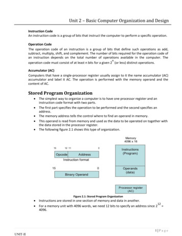
Steam Generator Configuration2134567891 Enclosure7 Water drain valveTerminal block2 Insulation bracket8 Subsidiary water tankFuse3 Circuit board9 Main water tankGround connector4 Steam OutletHeating Element5 Pressure relief valve221 F Hi-limitWater level sensor6 Water fill valveTransformer221 F Hi-limitO- 17 -RelayO
Trouble shooting:TroubleThe machine does not start when power issuppliedCauses of Trouble1.2.3.The fuse is burned.The wire connection terminal is loose.Bad Contact in the connection wirebetween the controller and the steamengine.1.2.The wire connector is damp or damaged.The heating tube breaksTrouble-Shooting Method1.2.3.1.GFCI switch breaks automaticallyWhen the machine is started, hot water comesout with little or no steam1.1.The display screen on the control panel does notdisplay2.1.Water leakageNo steam when starting the machineThe steam does not come out, there are watersounds in the machineThe light can not be turned onThe display box displays normally, but with nosteam input2.The water drainage valve is broken.The power wire is not connected properly.The connection plug between the controlpanel and the electrically-controlled box isloose.Trouble with plug board.The water pipe connector is loose or thepipe breaks.Water leakage in the water input valve orthe water drainage valve1.2.3.4.No electricityNo waterThe set temperature is too lowTrouble with wire1.The steam pipe is jammed.1.2.3.4.1.2.The fuse is burned.The light is broken.The wire is broken.The plug does not have good contactToo much pressure inside the steamengine, so the system breaks for heatprotection.The heat protection wire is broken.- 18 -Change the fuse (on the shell0.8A/250V)Plug-in the wire connection terminalMake sure the steam engine andthe controller is in good contact.2.Check whether the wire connectoris damp or damaged, and dry withdryer if dampened.Change the heating tube.1.Change the water drainage valve.1.Tighten the loose connector, andchange the broken pipe.Change the water input valve or thewater drainage valve.2.1.2.1.2.3.4.Tighten the loose connector,and change the broken pipe.Change the water input valveor the water drainage valve.Check the power supplyCheck the water input pipe andwater input valveReset the temperatureContact the distributor1.Cut power supply to check whetherthe steam pipe is smooth.1.Change the fuse (on the shell1A/250V)Change the light bulb.Change wire.Replace plug2.3.4.1.2.Check the team transport pipe andrestore automatically after heatprotection becomes cool.Check the heat protection wire tomake sure the connection is good.
SpecificationsImportant: The list below is for reference only. In actual checking and repairing, based on the national and local codes, ask professionalservice personnel for advice.Power Output3kW4.5kW6kW7.5kW9kW10.5kW12kW15kW18kWPotency Error 10% 10% 10% 10% 10% 10% 10% 10% 10%Duration 1500V 1500V 1500V 1500V 1500V 1500V 1500V 1500V 1500VResistance 20W 20W 20W 20W 20W 20W 20W 20W 20WSteam 0.16MPa0.16MPa0.16MPaSteam VolumeSteam Water Tank Volume2.5L2.5L5.7L5.7L5.7L12L12L12L12LApplicable space ofthe room (m3)3 64 75 87 910 1212 1414 1618 2020 24Important: The parameter listed in the above table may vary from place and temperature, please consult a qualified designer or architect formore detailed use.NOTE: Steam Bath Generators are considered to be able to cooperate above atmospheric pressure in abnormal operation and shalltherefore comply with UL clause 64.8.- 19 -
Part 2: Control PanelAttention: Before installing the controller, make sure the steam generator is shut off otherwise damage may occur.Do not use a controller inconsistent with the steam generator, do not use the controller to operate steam generator of other brand.The instructions include important safety, operation and maintenance information.Keep the instruction manual handy.If the steam generator is damaged or does not operate normally, do not continue to install or use.Control Panel Blueprint( mm)a- 20 -
Controller Installation instructionAttention: Before installing the controller, make sure the steam engine is shut off.Step oneDetermine the installation location of the controller.For installation:1.4 -5feet away from the ground.2.Locate controller on separate wall from steam nozzle.3.Do not expose yourself to the direct spray of steam.The controller wire is 1.5 feet long with a controller lengthened wire going tothe steam engine being 19.5 feet long. Installation of controller panel should bein a position not more than 21 feet from the steam engine.Attention: Do not install the controller under the water pipe or in a positionwhere water can easily make contact.Step twoDrill a round hole of 35mm in diameter in a chosen position.Step threePull the controller wire through the round hole, connect it to the corresponding wire in theengine.Attention: Do not over tighten or clip the controller wire.Step fourStart the power supply of steam engine, check and adjust connection, check each item on thepage to make sure all functions work properly.6thAttention: Before setting the controller,make sure the steam engine is shut off.Step fiveRemove the paper at the bottom.To achieve good adhesion, make sure surface is clean and dry.Step sixLocate the display screen at the 12 o'clock position, and press tight. Adhere controller to thewall.Attention: Level controller.IMPORTANT: PLEASE place sticker that comes with unit reading, “SAFETY SIGN FORSTEAM ROOMS OF COMMERCIAL STEAM BATH GENERATORS MENTIONED IN 66.4”visible location topass inspection requirements.- 21 -on a
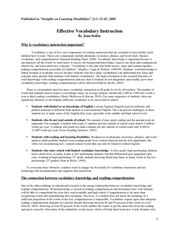
Temperature detector installation1.The position of the temperature sensor should be within 4-5ft above the ground. Try to avoid installing near the steam mouth or theopening side of the steam room door.As shown in Fig.1, drill a small hole (10mm) in the selected position.Apply silicone along the edge of the back of the detector foundation (as shown in Fig.2).Use a locknut to lock the detector foundation. (As shown in Fig.2)Push the temperature detector go through the back of the detector foundation (As shown in Fig.3)The temperature detector should be installed by extending about 1cm from the front of the room for accurate temperature.Apply silicone to the back and set the detector. (As shown in Fig.3)2.3.4.5.6.7.1cm10Temperature detectorfoundationDrill(Fig.1)Locknut for temperaturedetector foundationGround(Fig.2)1.2 1.5m(Fig.3)Controller Panel illustration1 Power ON/OFF2 Steam Indicator LED36 LED SCREEN7849 Power Indicator LED5Water drain KeyMood Light ON/OFF- 22 -
Operation Instruction:1. When power supply is applied to the steam box system the RED stand-by light will be illuminated. (see Illustration of the controllerpanel for location)2. Pressing the ON/OFF button will start the system. The steam box will fill with water. This will take a few minutes; the water may cycleon and off a few times as the water tank fills. This is normal operation. The display will show ambient Temperature and Running time – 8hrs.3. When the red light next to the ON/OFF button becomes
to wipe, and do not use erosive chemical solutions or abrasive cleaning tools. WARNING! The steam nozzle and steam outlet are very hot! Avoid installing the steam nozzle near steam bathers. 1. Install the steam nozzle 6-12 inches above the ground. If the steam bath is in the bathtub or