Transcription
Engineering DepartmentClimate Resilience DesignGuidelinesLast Updated: 06/01/2018Reviewed/Released 2018 v1.2
Engineering Department ManualClimate Resilience Design GuidelinesTABLE OF CONTENTS1.0 INTRODUCTION TO THE PANYNJ CLIMATE RESILIENCE GUIDELINES . 11.1BACKGROUND . 11.22018 CRG UPDATE SUMMARY. 11.3OBJECTIVES . 11.4CLIMATE PROJECTIONS . 21.5CLIMATE STRESSORS OTHER THAN SEA LEVEL RISE. 32.0 STRESSOR: SEA LEVEL RISE AND COASTAL INUNDATION . 42.1CODES AND STANDARDS. 42.2GRANT FUNDING. 42.3DESIGN CRITERIA . 5STEP 1: DETERMINE CRG APPLICABILITY. 5STEP 2: INCLUDE CLIMATE RESILIENCE IN PROJECT DOCUMENTS. 5STEP 3: ESTABLISH PROJECT DFE (SLR DFE) . 5STEP 4: DEVELOP RESILIENT DESIGN STRATEGIES . 9STEP 5: (IF APPLICABLE) CONDUCT A CLIMATE RISK-ENHANCED BENEFIT-COST ANALYSIS(BCA) 103.0 INTEGRATION OF CLIMATE RESILIENCE IN OTHER PANYNJ ENGINEERINGDISCIPLINE GUIDELINES . 11APPENDIX A - NEW YORK CITY PANEL ON CLIMATE CHANGE (NPCC) CLIMATECHANGE PROJECTIONS, 2015 . 12How to cite these Guidelines:Please reference these guidelines as “PANYNJ Climate Resilience Design Guidelines (v1.2), 2018”.Last Updated: 06/01/2018Reviewed/Released 2018 v1.2Page i
Engineering Department ManualClimate Resilience Design Guidelines1.0INTRODUCTION TO THE PANYNJ CLIMATE RESILIENCE GUIDELINES1.1BACKGROUNDIn June 1993, the Port Authority formally issued an environmental policy statement recognizing its longstanding commitment to provide transportation, terminal, and other facilities of commerce in anenvironmentally sound manner. In 2008, the Board of Commissioners reaffirmed its support of the PortAuthority’s continuing sustainability initiatives and expanded the Authority’s environmental policy to includeclimate change. The Sustainability Policy directs the Authority to “develop strategies that reduce the riskposed by climate change to its facilities and operations and, in collaboration with other regionalstakeholders, develop strategies that mitigate the risk to the region posed by climate change in a mannerthat will promote a sustainable environment.”To help fulfill this policy mandate, the Port Authority Engineering Department responded in 2009 by issuinga Design Memorandum dictating that “the design of all new construction and major rehabilitation projectsis to be evaluated based on climate change variables”, including temperature, precipitation, and sealevel rise. In 2015, this memorandum was replaced by the first edition of the PANYNJ Climate ResilienceDesign Guidelines (CRG), Version 1.0, which this document in turn supersedes.The Guidelines enable the Port Authority to proactively address projected risks during the design process,ensuring that public dollars are spent wisely to keep the region moving, now and in the future.1.22018 CRG UPDATE SUMMARYThe 2018 CRG update incorporates the lessons learned from over three years of implementation, as wellas feedback from representatives within the PA Engineering Department and Line Departments. Althoughthe CRG Version 1.1 does not substantially modify the Guidelines’ original technical basis, specific updatesto the CRG include: Simplified presentation of climate change projections; Streamlining of the Design Flood Elevation (DFE) determination process; Clarification of guidance for projects located outside of the current 1% annual chance floodplain,but which may be situated within the projected future floodplain.It is anticipated that subsequent editions will contain guidance on additional climate change stressors,including extreme temperatures and intense precipitation events.1.3OBJECTIVESThe purpose of the CRG is to maximize the long-term safety, service, and resilience of the Port Authority’sassets, now and in the future, as climate conditions change. The specific objectives of the CRG are to: Adopt a science-based approach to managing climate-related risks to Port Authority facilities andinfrastructure; Support the incorporation of climate change projections—particularly sea level rise—into the fullrange of Port Authority engineering and architectural design standards, as a supplement toapplicable building code requirements; Provide a clear methodology for factoring projected future sea level rise into project designcriteria, while maintaining the flexibility of project teams to develop cost-effective design solutions;and Support our Line Departments and Office of Emergency Management to ensure that, whennatural disasters inevitably strike, Port Authority facilities and infrastructure are better equipped towithstand the impacts and to recover and restore operations more quickly.Last Updated: 06/01/2018Reviewed/Released 2018 v1.2Page 1
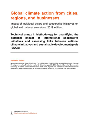
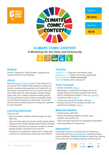
Engineering Department ManualClimate Resilience Design Guidelines1.4CLIMATE PROJECTIONSThe New York City Panel on Climate Change (NPCC) has been instrumental in providing a common basisof scientific knowledge for agencies in the region. Climate change projections referenced in this documentwere obtained from NPCC’s Building the Knowledge Base for Climate Resilience: New York City Panel onClimate Change 2015 Report1. The report provides recently observed trends and projections up to the year21002, applicable to a 100-mile radius around the New York City metropolitan area. Figure 1 displays theNPCC’s regional sea level rise projections for the greater New York City area3. A summary of the NPCC’scurrent mid-range climate projections (25th to 75th percentile) 4 is included as Appendix A.Figure 1. NPCC Sea Level Rise Projections, 2015As of May 2018, the climate change projections cited in this document are complete and accuratelytranscribed from NPCC. The Port Authority will continue to update the CRG as climate models evolve. Asappropriate, design teams may opt additionally to consider customized downscaling or site-specificanalyses, subject to approval by the Chief, Resilience & Sustainability.NPCC’s 2015 projections are summarized below, along with potential implications for Port Authorityfacilities and infrastructure.1References to climate change projections obtained from pages 9-11, 31-32 of the Annals of the New York Academy of Science, Vol. 1336:Building the Knowledge Base for Climate Resilience: New York City Panel on Climate Change 2015 Report, Pages yas.2015.1336.issue-1/issuetoc).2 Leveraging the methods and projections produced at a global scale by the Fifth Assessment Report of the Intergovernmental Panel on ClimateChange.3 Annals of the New York Academy of Science, Vol. 1336: Building the Knowledge Base for Climate Resilience: New York City Panel on ClimateChange 2015 Report, Page 41.4 Percentiles are used by the NPCC to characterize the range of projections from a variety of models. The 25th to 75th percentile rangerepresents the middle 50 percent of projections, meaning that of the total climate model outputs, 25 percent were lower and 25 percent werehigher than this range. Consistent with CRG 1.0, PANYNJ uses the mid-point of this range.Last Updated: 06/01/2018Reviewed/Released 2018 v1.2Page 2
Engineering Department ManualClimate Resilience Design GuidelinesProjected Climate Change HazardPotential Impacts to Port AuthoritySea Level Rise:--Observed relative sea level rise of about1.2 inches per decade (which includesfactors such as land subsidence) in thegreater New York City region has averagedtwice the observed global rate.Sea level rise is very likely ( 90%probability of occurrence) to accelerate asthe century progresses.-Amplifies the depth and extent of storm surge, putting moreareas at risk of flooding during coastal storm events.-Increasing depth and extent of coastal inundation duringextreme and regular high tides.-Increased likelihood of backflow from drainage outfalls.-Progressively greater risk of groundwater flooding incoastally connected areas.-Corrosion of tracks and equipment from saltwaterexposure.-Diminishing air draft below bridge spans.-Greater volumes of rain in more concentrated downpourscould overwhelm drainage systems and cause localizedflooding.-Disruption to movement of transit vehicles and freight bothduring and after significant precipitation events.-Erosion and scour of foundations, pilings, footings, andshorelines from overland flow.-Additional stress on drainage and pumping systems.Precipitation:-The number of annual rainfall downpours isvery likely ( 90% probability of occurrence)to increase.Rising Temperatures:-Warmer temperatures are extremely likely( 95% probability of occurrence)-Impacts to materials, such as expansion and kinking ofsteel rails.-Average number of days per year withtemperatures at or above 90 F is projectedto more than double to 39-52 days by the2050s5.-Increasing summer electricity loads possibly leading toblackouts or brownouts and service disruptions.-Stress on air conditioning systems in vehicles, stations, andoperational facilities.Heat waves (3 days or more exceeding90 F) are projected to occur with greaterfrequency.-Heat stress on critical mechanical/electrical equipment.-Heat stress on maintenance crews, operators, andpassengers.-1.5CLIMATE STRESSORS OTHER THAN SEA LEVEL RISEAt this time, the CRG Version 1.1 provides explicit design guidance only for managing the risks of coastalflooding, as amplified by projected sea level rise. As the state of the practice evolves, it is anticipated thatfuture versions of the Guidelines will additionally consider the changing risk profiles of extreme precipitationand heat events. Until then, design teams are encouraged to work with the Resilience & Sustainable Design(RSD) group to develop design criteria for future extreme heat, precipitation, and other stressors asappropriate. PA Line Departments may also request consideration of extreme precipitation and heat eventsin their Project Initiation Request Forms (PIRF).525th to 75th percentile (“mid-range”) projections.Last Updated: 06/01/2018Reviewed/Released 2018 v1.2Page 3
Engineering Department ManualClimate Resilience Design Guidelines2.0STRESSOR: SEA LEVEL RISE AND COASTAL INUNDATION2.1CODES AND STANDARDSThe Port Authority takes a code-plus approach to designing for future sea level rise, meaning that theClimate Resilience Guidelines supplement, but do not supersede, applicable codes and standards 6.The American Society of Civil Engineers (ASCE) standard Flood Resistant Design and Construction (ASCE24) is fully incorporated into New Jersey Building Code and serves as the basis for New York City BuildingCode Appendix G (Flood-Resistant Construction). ASCE 24 dictates that construction in the FEMA 1%(“100-year”) annual chance floodplain is subject to specific, safety-driven requirements, most notably theestablishment of a Design Flood Elevation (DFE) comprising: Base Flood Elevation. The project-specific FEMA Base Flood Elevation (BFE)7—the elevationof the 100-year flood including waves—is derived from the FEMA Flood Insurance Rate Map(s);and Freeboard. Freeboard is a factor of safety usually expressed in feet above the BFE, as dictatedby the requirements of ASCE 24 or the applicable code.The Climate Resilience Guidelines supplement ASCE 24 and applicable local codes in two primary ways:2.2 Adjustment of the BFE for Sea Level Rise: The Guidelines augment the applicable FEMA BFEby adding the relative increase in future sea levels (based on the NPCC projections) over theproject’s expected service life8. Consideration of future floodplain expansion: Rising sea levels may also lead to expansionof the 100-year tidal floodplain over time, depending on local conditions. Therefore, theGuidelines apply to projects sited in or proximate to today’s 0.2% annual chance (“500-year”)floodplain or in the projected future tidal 100-year floodplain, in addition to the current FEMA 100year floodplain.GRANT FUNDINGProjects receiving federal, state or local funding may be required to adhere to specific design criteria. Insuch instances, the design lead (LE/A or Principal) should contact the Line Department Project Managerearly in the process to identify any design requirements stipulated in the grant agreement. If the project isreceiving funding from FEMA, FTA, or other entities, the design lead should additionally contact the ClimateResilience Specialist (resilience@panynj.gov) and the Engineering Program Management group duringproposal development.6In the unlikely instance that these Guidelines are found to be less stringent than code in a particular application, code prevails.FEMA Region 2 defines Base Flood Elevation (BFE) as the elevation shown on the Flood Insurance Rate Map (FIRM) for Zones AE, AH, A1-30, orVE that indicates the water surface elevation resulting from a flood that has a 1% chance of occurring in any given year.8Where it is necessary or useful to differentiate between code-required design flood elevations and the DFEs derived from these Guidelines,use “SLR DFE” in drawings, notes, and narratives to indicate that the DFE has been adjusted for projected future sea level rise.7Last Updated: 06/01/2018Reviewed/Released 2018 v1.2Page 4
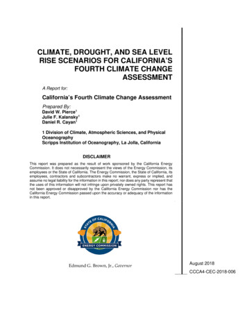
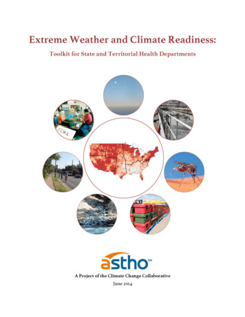
Engineering Department ManualClimate Resilience Design Guidelines2.3DESIGN CRITERIAThere are five principal steps for developing the sea-level rise adjusted project DFE (SLR DFE). Forquestions about this process, please contact the Climate Resilience Specialist at resilience@panynj.gov.Step 1: Determine CRG ApplicabilityThese Guidelines apply to Port Authority projects where at least one of the following criteria is true:1) The project is located in or is potentially hydrologically or hydraulically connected 9 to a federallydelineated tidal floodplain (Effective or Preliminary);2) (Advisory) The project is located in a projected future tidal floodplain, as defined by the FutureFlood Risk Mapper10, an application created by the City of New York and adapted for portions ofnorthern New Jersey11 by the Port Authority.Please contact the Climate Resilience Specialist with questions concerning the applicability of the CRG toyour project, or email resilience@panynj.gov.Step 2: Include Climate Resilience in Project DocumentsInterdependent RisksEarly integration of the CRG criteria into the project delivery process isessential to ensuring an effective and cost-conscious outcome.Consequently, the CRG must be referenced in the following documents, ifapplicable:As part of Step 2, considerwhether there may be anopportunity to addresscritical interdependencies(for example, shared ing, or surface accessinfrastructure) within theproject scope. The project Proposal; The Attachment A for consultant services; Design Criteria/Performance Criteria/Basis of Design documents; Requirements and Provisions for Work;Further, invite the Climate Resilience Specialist to the kick-off meeting.Step 3: Establish Project DFE (SLR DFE)The design team must assemble three sources of information to compute the project’s sea level riseadjusted Design Flood Elevation:1. FEMA Base Flood Elevation (BFE)2. Asset Service Life3. Asset CriticalityThe key informational requirements for determining the project DFE are summarized in Figure 2, below,followed by detailed guidance.9Via storm drain, channel, or ditch, for s/flood-hazard-mapper.page11 PA staff may access this resource from the RSD SharePoint site. Consultants may request access through the project Lead Engineer/Architect.10Last Updated: 06/01/2018Reviewed/Released 2018 v1.2Page 5
Engineering Department ManualClimate Resilience Design GuidelinesFigure 2: Key Information for DFE DeterminationProjected Base Flood Elevation (BFE Sea Level Rise)Freeboard1) FEMA Base Flood Elevation2) Asset Service Life3) Asset CriticalityIs the project in or proximate toa current or projected futureFEMA floodplain?When will the expected servicelife end?Is it classified as critical?NoYes20212050CRG notapplicableReferencethe nearestplausibleBase FloodElevationSource: Access FEMA’s EffectiveFlood Insurance Rate Maps(FIRMs) online here.12 PreliminaryFIRMs can be viewed usingFEMA’s Preliminary FIRM Viewer.133.120512080 28”YesAdd ”12FreeboardAdd 24”(or 36”)Freeboard2081 Add SLR Adjustment to BFE 16”No 36”Source: Use the PA Asset ClassReference Manual14 for guidance,complemented by best engineeringjudgment and Line Departmentconsultation.Source: Refer to applicable buildingcode to determine the Flood DesignClass, or reference criticalinfrastructure types in Step 3.3 of thisdocument.FEMA Base Flood Elevation (BFE)Overlay the project footprint on the applicable Preliminary and Effective FEMA Flood Insurance Rate Maps(FIRM) and, consistent with local building codes, select the more conservative (higher) Base FloodElevation among the two. Convert the BFE into the North American Vertical Datum of 1988 (NAVD88), ifnecessary15.For CRG-applicable projects outside of the current 1% annual chance floodplain (e.g., in the 0.2% annualchance floodplain or in a projected future 1% annual chance floodplain, per the applicability criteria in Step1), select the nearest plausible Base Flood Elevation, accounting for subsurface (e.g., drainage and/orseepage) connectivities and/or structurally-sound obstructions to overland flows.FEMA FIRMs are available online (as of May 2018): Effective FIRMs (2007): https://msc.fema.gov/portal/advanceSearch Preliminary FIRMs (2013/2015): /14 https://panynj.sharepoint.com/sites/Engineering/ layouts/15/DocIdRedir.aspx?ID ENGDEPT-1823177521-1415 Note that the Effective FIRM references the outdated NGVD29 datum, whereas the Preliminary FIRM references the required NAVD88datum. For guidance on conversion, consult Central Survey or visit: tanding-verticaldatums13Last Updated: 06/01/2018Reviewed/Released 2018 v1.2Page 6
Engineering Department ManualClimate Resilience Design GuidelinesContact the Climate Resilience Specialist (resilience@panynj.gov) for information on pending FEMA floodmap appeals, revisions, or amendments, if applicable.In instances where higher resolution or more up-to-date flood risk information is available, as validated bythe Climate Resilience Specialist, these additional sources should be factored into determination of theproject DFE (unless the alternative information results in an DFE less stringent than applicable codes andstandards). Such sources may include: NOAA’s Hurricane SLOSH maps; Hurricane Sandy inundation maps; USACE’s North Atlantic Coast Comprehensive Study maps; Site-specific flood hazard analyses.3.2Asset Service LifeSea level rise is already impacting the Port District, with over 14 inches of increase in mean sea levelobserved at the Battery since the year 190016, an average rise of 1.2 inches per decade. The rate ofincrease is projected to accelerate as the 21st century progresses, likely leading to a significant rise in boththe frequency and magnitude of coastal flooding. To help mitigate these risks, the Authority supplementsthe applicable FEMA Base Flood Elevation with projected sea level rise, commensurate with the expectedservice life of the asset(s) being designed.For guidance on determining an asset’s expected service life, refer to the Port Authority Asset ClassReference Manual. This reference should be complemented by the engineering judgment of the designteam, in consultation with the appropriate Line Department or facility. A conservative estimate isrecommended, as the service life of a given asset may vastly exceed its original design life.Based on the anticipated end year of a given asset’s expected service life, use Table 1, below, to determinethe appropriate sea level rise adjustment factor to be added to the Base Flood Elevation established in Step3.1. No SLR adjustment is required if a given project’s service life will terminate prior to January 1, 2021.Table 1. Sea Level Rise Adjustment Factors16End of AnticipatedAsset Service LifeSea Level Rise Adjustment2021-2050 16”2051-2080 28”2081 Last Updated: 06/01/2018Reviewed/Released 2018 v1.2Page 7
Engineering Department ManualClimate Resilience Design Guidelines3.3Asset CriticalityAn asset’s classification as Critical or Non-Critical determinesthe level of code-required freeboard, a safety factor added to theBFE. Freeboard typically adds 1 foot (non-critical) or 2 feet(critical) to the BFE, but can be as high as 3 feet in certaincircumstances.The determination of asset criticality is driven primarily by thefollowing local codes and national standards, depending on thehost jurisdiction: New Jersey: New Jersey Building Code (IBC), whichpoints to ASCE-24, Table 1-1 Flood Design Class ofBuildings and Structures; or New York City: New York City Building Code, whichpoints to Appendix G, Table 1-1 Classification ofStructures for Flood-Resistant Design andConstruction.Under both building codes, Flood Design Classes 1 and 2 areconsidered “Non-critical,” while Classes 3 and 4 are considered“Critical.”Calculation of Flood LoadsFlood load calculations mustincorporate projected future sealevel rise for all applicableprojects. To calculate flood loads,augmenttheBaseFloodElevation by the appropriate SLRadjustment factor (see Steps 3.1and 3.2). Where SLR is likely toresult in landward migration of theVE Zone, factor in breaking waveloads as appropriate.ConsistentwithASCE7,Minimum Design Loads forBuildings and Other Structures,freeboard should be omitted fromflood load calculations.In addition, the following Port Authority infrastructure types follow ASCE-24 freeboard requirements forCategory 4 structures: PATH Tunnels (e.g., entrances, penetrations, vent buildings); Vehicular Tunnels (e.g., entrances, penetrations, vent buildings); Power distribution facilities (e.g., electrical substations, switch houses, transformers); Emergency generators; Fire Protection Systems; and Aircraft Fueling Systems.Additions or subtractions of assets to the list above require agreement between the respective LineDepartment Director and the Chief Engineer.3.4Sea Level Rise Adjusted DFEBased on the information collected in Steps 3.1 through 3.3, calculate the sea level rise-adjusted DFE (SLRDFE) for the project. Refer to Table 2 for non-critical assets and Table 3 for critical assets.Table 2. SLR DFE for Non-Critical Assets1) FEMA Base FloodElevation (BFE)Project specific (seeStep 3.1 for guidance)2) Sea Level Rise Adjustmentbased on Asset Design Life3) Freeboard(code-required)DESIGN FLOODELEVATION (SLR DFE)2021-2050 16” 12” FEMA BFE 28”2051-2080 28” 12” FEMA BFE 40”2081 36” 12” FEMA BFE 48”Last Updated: 06/01/2018Reviewed/Released 2018 v1.2Page 8
Engineering Department ManualClimate Resilience Design GuidelinesTable 3. SLR DFE for Critical Assets1) FEMA Base FloodElevation (BFE)Project specific (seeStep 3.1 for guidance)2) Sea Level Rise Adjustmentbased on Asset Design Life3) Freeboard17(code-required)DESIGN FLOODELEVATION (SLR DFE)2021-2050 16” 24” FEMA BFE 40”2051-2080 28” 24” FEMA BFE 52”2081 36” 24” FEMA BFE 60”Step 4: Develop Resilient Design StrategiesThis Guideline sets out the methodology for incorporating projected sea level rise into project design criteria,but preserves the flexibility of project teams to develop packages of flood mitigation solutions that bestsatisfy broader design objectives in a cost-effective and co-beneficial manner18.Approaches to increasing the resilience of an asset to flood damage and/or operational disruption generallyfall into the basic categories of a) elevate, b) relocate, c) protect, or d) accommodate. These approachesinclude, but are not limited to: Coastal protection, including wave attenuation (placement of levees, berms, or livingshorelines)19; Site selection and relocation (placement of structures on higher ground or within flood protectedareas); Perimeter protection (placement of flood walls and/or deployable protection measures to limitflood risk within a defined perimeter); Elevation (raising an entire structure above the DFE); Elevation of utilities and critical equipment such as controls, outlets, generators, etc.; Wet floodproofing (allowing floodwaters to enter and exit certain non-critical, generallyunoccupied portions of a structure to equalize flood loads, subject to code restrictions); Dry floodproofing (placement of permanent, deployable, and/or temporary mitigation measures toprevent intrusion of flood waters into a structure); Pumps (to prevent build-up of incidental leakage in a dry floodproofed structure or perimeterprotected site); Backflow prevention (the installation of devices to prevent surge intrusion through storm orsanitary sewers).17See New York City Building Code, Appendix G for circumstances in which 3 feet of freeboard are required, which must be reflected in the SLRDFE.18 Subject to the restrictions of applicable codes, standards, and PANYNJ Engineering Guidelines.19 In certain instances, the elevation of coastal/perimeter protection structures may be lower than the SLR DFE as long as all applicablelandward/perimeter-enclosed assets are designed in accordance with these Guidelines, subject to the restrictions of codes, standards, andother PANYNJ Guidelines.Last Updated: 06/01/2018Reviewed/Released 2018 v1.2Page 9
Engineering Department ManualClimate Resilience Design GuidelinesFlood Mitigation Product LibraryTo support design teams in identifying potentialflood mitigation products and systems, the PortAuthority Resilience & Sustainable Design unitoffers an extensive product library of floodmitigation products (for informational use only).PA staff may access this resource from the RSDSharePoint site. Consultants may request accessthrough the project Lead Engineer/Architect.A viable flood protection system may incorporateseveral of the preceding strategies. For the mostcritical assets—for which loss of operation for anyperiod of time would be unacceptable—multiplelayers of redundant protection may be preferable.The PANYNJ Climate Resilience Specialist isavailable to meet with project teams to discussflood mitigation approaches and product options.Step 5: (If Applicable) Conduct A Climate Risk-Enhanced Benefit-Cost Analysis (BCA)At the request of the Line Department or if required for a given funding source, Benefit-Cost Analysis (BCA)can be employed to inform design decision-making. Climate risk-enhanced BCA considers the incrementalcapital and/or operating costs of designing for resilience (i.e., only the portion of Total Project Cost attributeddirectly to the additional consideration of sea level rise) in balance with projected avoided losses over timedue to flood-related failures.Climate risk-enhanced BCA has at least two potential applications in the context of climate resilient design: Typically, to support selection of the most cost-effective flood mitigation alternative during Stage Idesign services; Selectively, to determine whether a Stage III flood mitigation design to the required DFE isappropriately cost effective. If the BCA definitively demonstrates that design to the full DFE is notcost beneficial, the design team may pursue a flexible adaptation pathway 20 approach, inconsultation with the Climate Resilience Specialist.The Resilience & Sustainable Design unit and the Economics unit of the PANYNJ Office of Planning andRegional Development collaborate to perform the climate-risk enhanced BCA, on request. This serviceshould be specified in the project Proposal and Attachment A, if applicable. Contact the Climate ResilienceSpecialist with questions pertaining to the BCA process at resilience@panynj.gov.20A Flexible Adaptation Pathway is one or more “[r]esilience-building strategies that can evolve or be adapted over time ” as betterinformation becomes available. NYC Climate Resiliency Design Guidelines, Version 2.0 (April 2018).http://www1.nyc.gov/assets/orr/pdf/NYC Climate Resiliency Design Guidelines v2-0.pdfLast Updated: 06/01/2018Reviewed/Released 2018 v1.2Page 10
Engineering Department ManualClimate Resilience Design Guidelines3.0INTEGRATION OF CLIMATE RESILIENCE IN OTHER PANYNJ ENGINEERINGDISCIPLINE GUIDELINESThere are a number of intersections between the CRG and the design guidelines of other Port AuthorityEngineering disciplines. Provided below is a basic summary of how climate resilience is explicitly integratedinto other Engineering design guidelines at PANYNJ, as of the issuance date of this document.Table 4. PAN
a Design Memorandum dictating that “the design of all new construction and major rehabilitation projects is to be evaluated based on climate change variables”, including temperature, precipitation, and sea level rise. In 2015, this memorandum was repla