Transcription
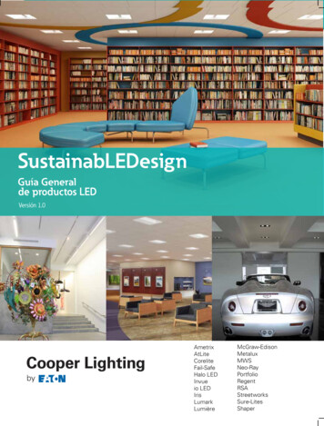
TI Designs: TIDA-050011Various LED Ring Lighting Patterns Reference DesignDescriptionThis reference design enables human-machineinterface scenarios with an LED ring that utilizes twoLP5024 LED drivers to create vivid lighting patterns.Design helps to resolve common challenges for endequipment with complicated lighting patterns andconstant voltage supply. This design can also adjustLP5024 brightness with analog dimming withoutimpacting the lighting pattern contrast ratio on dynamicambient light sense.Applications Smart Speaker (With Voice Assist) Appliances User Interface and ConnectivityModules Video Doorbell Electronic Smart Lock STB and DVR WLAN/WIFI Access Point Virtual- and Augmented-Reality Headsets andGlasses Printers Video Game Console Home Theater-in-a-Box (HTiB)ResourcesTIDA-050011LP5024OPT3001SimpleLink MSP432P401RLaunchPad Development KitDesign FolderProduct FolderProduct FolderTool FolderASK Our E2E ExpertsVLEDCH0Features Vivid Lighting Patterns With 12-Bit, 29-kHz PWMDimming Through and I2C Interface Ultra-Low Standby Current Down to 10 µA WithAutomatic Power Saving Mode Programmable Banks (R/G/B) for Easy SoftwareControl of Each Color Dynamically Adjusts Brightness on Ambient 2CH23CH22VCCOPT3001VCCLP5024EN SDA SCL ADDR0 ADDR1 VCAPGNDIREFVCCGNDSDA SCL ADDRVCCLP5024EN SDA SCL ADDR0 ADDR1 VCAPGNDIREFVCCMCUAn IMPORTANT NOTICE at the end of this TI reference design addresses authorized use, intellectual property matters and otherimportant disclaimers and information.TIDUEE6 – November 2018Submit Documentation FeedbackVarious LED Ring Lighting Patterns Reference DesignCopyright 2018, Texas Instruments Incorporated1
System Description1www.ti.comSystem DescriptionThis is the design guide for the Various LED Ring Lighting Patterns Reference Design, which makes thevivid lightings pattern on the LED ring with 2 LP5024 devices. In this reference design, LP5024 linear LEDdrivers are used to drive 16 RGB LED modules with constant current control. OPT3001 senses theambient light dynamically. The MSP432P401R LaunchPad sends the control signal to adjust LP5024analog current and generate the various lighting patterns.1.1Key System SpecificationsTable 1. Key System SpecificationsPARAMETER2SPECIFICATIONSInput voltage range3 V to 5.5 VOutput current8 mA/channel maximumLED number16 RGBLED type19-337/R6GHBHC-A01/2TLighting pattern style7Analog dimming control range1% to 100%Various LED Ring Lighting Patterns Reference DesignCopyright 2018, Texas Instruments IncorporatedTIDUEE6 – November 2018Submit Documentation Feedback
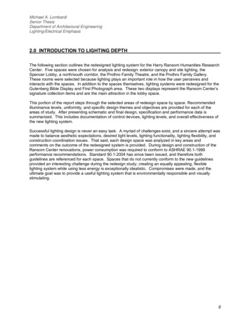
System Overviewwww.ti.com2System Overview2.1Block DiagramFigure 1. TIDA-050011 Block DiagramVCCVLEDVCCENCH0SDACH1SCLCH2ADDR0 PT3001ADDRGNDVCCVLEDVCCENCH0SDACH1SCLCH2VCCADDR0 LP5024ADDR1CH21VCAPCH22CH23IREFGNDTIDUEE6 – November 2018Submit Documentation FeedbackVarious LED Ring Lighting Patterns Reference DesignCopyright 2018, Texas Instruments Incorporated3
System Overview2.2www.ti.comDesign ConsiderationsIn this reference design, two 24-channel, 12-bit, PWM ultralow-quiescent-current, I2C RGB LED drivers(LP5024) are used to drive a 16-RGB-LED module with constant current control and smooth dimmingeffect. The LP5024 devices improve the user experience in color mixing and brightness control for bothlive effects and coding efforts. The optimized performance for RGB LEDs makes the LP5024 an excellentfit for human-machine interaction applications. OPT3001 senses the ambient light dynamically. TheMSP432P401R LaunchPad sends the control signal to adjust LP5024 analog current and generate thevarious lighting patterns.Several considerations are taken into account for this particular design: LED map (ring) for meeting the requirement of popular human-machine interaction style. LED size, numbers and the diffuse design for meeting lighting pattern uniformity. Analog dimming in the difference ambient light lux without losing dimming resolution in lighting pattern.These considerations apply to most human-machine interaction end equipment with day and night visiondesigns in some way, but the designer must decide the particular considerations to take into account for aspecific design.2.3Highlighted ProductsThe following highlighted products are used in this reference design. The key features for selecting thedevices for this reference design are outlined in the following subsections. For the complete details of thehighlighted devices, refer to their respective product data sheets.2.3.1LP5024 24-Channel, 12-Bit, PWM Ultralow-Quiescent-Current, I2C RGB LED DriverThe LP5024 device is an 24-channel constant current-sink LED driver. The LP5024 device improves theuser experience in color mixing and brightness control, from both live effects and coding efforts. Theoptimized performance for RGB LEDs makes it a potential choice for human-machine-interactionapplications.The LP5024 device controls each LED output with a 12-bit PWM resolution at 29-kHz switching frequency,which helps achieve a smooth dimming effect and eliminates audible noise. The independent color mixingand brightness control registers make the software coding straightforward. When targeting fade-in, fadeout type breathing effect, the global R, G, B bank control reduces the microcontroller loading significantly.The LP5024 device also implements a PWM phase-shifting function to help reduce the input power budgetwhen LEDs turn on simultaneously.2.3.2SimpleLink MSP432P401R LaunchPad Development KitThe SimpleLink MSP‑EXP432P401R LaunchPad development kit enables one to develop highperformance applications that benefit from low-power operation. This kit features the MSP432P401RLaunchPad, which includes a 48-MHz Arm Cortex -M4F, 80-μA/MHz active power and 660-nA RTCoperation, 14-bit 1- MSPS differential SAR ADC, and AES256 accelerator. All pins of the MSPEXP432P401R device are fanned out for easy access. These pins make it easy to plug in 20-pin and 40pin BoosterPack modules that add additional functionality including Bluetooth low energy, Wi-Fi wireless connectivity, and more.4Various LED Ring Lighting Patterns Reference DesignCopyright 2018, Texas Instruments IncorporatedTIDUEE6 – November 2018Submit Documentation Feedback
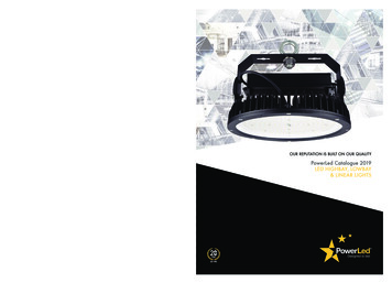
System Overviewwww.ti.com2.3.3OPT3001 Digital Ambient Light Sensor (ALS) With High-Precision Human-Eye ResponseThe OPT3001 is a sensor that measures the intensity of visible light. The spectral response of the sensortightly matches the photopic response of the human eye and includes significant infrared rejection.The OPT3001 is a single-chip lux meter, measuring the intensity of light as visible by the human eye. Theprecision spectral response and strong IR rejection of the device enables the OPT3001 to accuratelymeter the intensity of light as seen by the human eye regardless of light source. The strong IR rejectionalso aids in maintaining high accuracy when industrial design calls for mounting the sensor under darkglass for aesthetics. The OPT3001 is designed for systems that create light-based experiences forhumans, and an ideal preferred replacement for photodiodes, photoresistors, or other ambient lightsensors with less human eye matching and IR rejection.Measurements can be made from 0.01 lux up to 83 k lux without manually selecting full-scale ranges byusing the built-in, full-scale setting feature. This capability allows light measurement over a 23-bit effectivedynamic range.2.4System Design TheoryTwo 24-channel, 12-bit, PWM ultralow-quiescent-current, I2C RGB LED drivers (LP5024) are used todrive a 16-RGB-LED module with constant current control and a smooth dimming effect. OPT3001 sensesthe ambient light dynamically. The MSP432P401R LaunchPad sends the PWM control signal to adjustLP5024 analog current and refresh the LP5024 device registers to generate the various lighting patterns.2.4.1Power Supply Design TheoryThe LEDs (VLED) are powered by the external DC power directly or 3.3 V from the MSP432P401RLaunchPad through J8 (VINSEL).The 3.3-V blue and green LEDs, which forward voltage can use separate power from the red LEDbecause the red LED forward voltage is 1.8 V. The lower input voltage for the red LED reduces the powerdissipation from the LED driver. J7 is the configuration jumper.LP5024 supports 1.8-V, 3.3-V, and 5-V I2C communication logic leves, which means the difference powerrail can be used in VCC, I2C interface and VLED. The device also can be configured through J1, J2, andJ3.Figure 2. Power DesignJ11 VMCU2 VCCVMCU VCCJ2J3VCC VLEDVIN EXT1 VLED2 VMCUVLED VMCU1 VCC2 VLEDVINSELJ7VBGVLED1352463 VIN EXT2 VLED3.3V1 VINLVR EXTVRVLEDJ8C110µFGNDTIDUEE6 – November 2018Submit Documentation FeedbackVarious LED Ring Lighting Patterns Reference DesignCopyright 2018, Texas Instruments Incorporated5
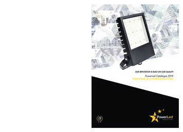
System Overview2.4.2www.ti.comLED Design16 RGB LED modules were placed as the LED rings for the popular human-machine interaction style. Thisdesign uses two LP5024 devices.Figure 3. LED DesignVCCTP2VMCUR14.7kR24.7kC71µFR34.7kC80.1 µFGNDU1J6C61µF321ENENVCC27U1VCAP32IN 32VCCGNDNCGNDR14GNDGND10kGND127U2VCAP32IN 0kGNDD13BU2OUT2RC40.1 22232419-337/R6GHBHC-A01/2TRgbLED CurrentThe maximum current of each LED is 8 mA.The constant-current value (ISET) of all 24 channels is set by a single external resistor, RIREF. The value ofRIREF can be calculated by Equation 1.VIREFRIREF KIREF ISETwhere: KIREF 105VIREF 0.7 V(1)The maximum current of each LED is 8 mA.Select R4, R5, R6, R7 with a value of 5.1 kΩ.6Various LED Ring Lighting Patterns Reference DesignCopyright 2018, Texas Instruments IncorporatedTIDUEE6 – November 2018Submit Documentation Feedback
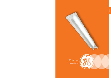
System Overviewwww.ti.com2.4.2.2LP5024 Analog Dimming Circuit DesignThe source current of IREF pin determines the LP5024 constant-current value (ISET). The input PWMsignal filters it as DC voltage with a large capacitor. The IREF is calculated from equations based on theschematic.Figure 4. Analog Dimming SchematicC31µFC40.1 µFGNDU2VCC27U2VCAP32IN GNDLP5024RSM/LP5018RSMVIREF u DR4 R5 u DIIREFIoutxKIREF u IIREFKIREF u VIREF u DR4 R5 u Dwhere K R5 / (R4 R5)D is duty cycle of the PWMMake R4 R5, then K 1/2.KIREF u VIREF u DIoutxR4 u 1 D2.4.3OPT3001 DesignUse the OPT3001 typical application to measure ambient light lux. Make sure that the C1 capacitor isplaced close to the VDD pin.Figure 5. OPT3001 DesignU3VCC1VDDC100.1 10K37OPT3001DNPRI2C Address 100 0100 (x44)TIDUEE6 – November 2018Submit Documentation FeedbackGNDVarious LED Ring Lighting Patterns Reference DesignCopyright 2018, Texas Instruments Incorporated7
System Overview2.4.4www.ti.comRelation Between Pattern Brightness and Ambient Light LuxWhen lux is 0, the minium brightness is 1%. When lux is higher than 2000, the maximum brightness is100%. When the lux is between 0 and 2000, the brightness has a linear relation with the lux.2.4.5Pattern Brightness AlgorithmRead the lux value from the OPT3001 device register and covert it a decimal format. Next, adjust thepattern brightness based on the lux value through PWM.After the reading the lux, use the following sample code to transfer it to decimal format.unsigned long int OPT3001 getLux(){/* Specify slave address for OPT3001 */I2C setslave(OPT3001 SLAVE ADDRESS);uint16 t exponent 0;uint32 t result 0;int16 t raw;raw I2C read16(RESULT REG);/*Convert to LUX*///extract result & exponent data from raw readingsresult raw&0x0FFF;exponent (raw 12)&0x000F;//convert raw readings to LUXswitch(exponent){case 0: //*0.015625result result 6;break;case 1: //*0.03125result result 5;break;case 2: //*0.0625result result 4;break;case 3: //*0.125result result 3;break;case 4: //*0.25result result 2;break;case 5: //*0.5result result 1;break;case 6:result result;break;case 7: //*2result result 1;break;case 8: //*4result result 2;break;case 9: //*8result result 3;break;case 10: //*16result result 4;break;case 11: //*32result result 5;break;}return result;}8Various LED Ring Lighting Patterns Reference DesignCopyright 2018, Texas Instruments IncorporatedTIDUEE6 – November 2018Submit Documentation Feedback
System Overviewwww.ti.comAdjust the brightness using the following function.void{adjustb(void)float lux;lux OPT3001 getLux();/* Adjust Peak Current */if (lux 2000)pwmConfig.dutyCycle ((2000*0.01) (lux*0.98))/2000 * 128;elsepwmConfig.dutyCycle 128;MAP Timer A generatePWM(TIMER A0 BASE, &pwmConfig);}2.4.6Lighting Pattern DesignDefine the LP5024 register operation function with the following code:void Shutdown(){GPIO setOutputLowOnPin(GPIO PORT P5, GPIO PIN6);//Set Enable to Low to enter SHUTDOWN mode}void Initialization(){GPIO setOutputHighOnPin(GPIO PORT P5, GPIO PIN6);//Set Enable to High to enter INITIALIZATIONmode}void Mode Select Standby()//Set Chip EN 0 to enter STANDBY mode{MAP I2C setSlaveAddress(EUSCI B1 BASE, SLAVE ADDRESS);MAP I2C masterSendMultiByteStart(EUSCI B1 BASE, 0x00); //send register addressMAP I2C masterSendMultiByteFinish(EUSCI B1 BASE,0x00); // send register data}void Mode Select Normal()//Set Chip EN 1 to enter NORMAL mode{MAP I2C setSlaveAddress(EUSCI B1 BASE, SLAVE ADDRESS);MAP I2C masterSendMultiByteStart(EUSCI B1 BASE, 0x00); //send register addressMAP I2C masterSendMultiByteFinish(EUSCI B1 BASE,0x40); // send register data}/*Device Configure*/void Device Config1(bool Log Scale EN, bool Power Save EN, bool Auto Incr EN, boolPWM Dithering EN, bool Max Current Option, bool LED Global Off){charconfig1 Log Scale EN*32 Power Save EN*16 Auto Incr EN*8 PWM Dithering EN*4 Max Current Option*2 LED Global Off;MAP I2C setSlaveAddress(EUSCI B1 BASE, SLAVE ADDRESS);MAP I2C masterSendMultiByteStart(EUSCI B1 BASE, 0x01); //send register addressMAP I2C masterSendMultiByteFinish(EUSCI B1 BASE,config1); // send register data}/*Bank Select*/void LED CONFIG0(bool LED7 Bank EN, bool LED6 Bank EN, bool LED5 Bank EN, bool LED4 Bank EN, boolLED3 Bank EN, bool LED2 Bank EN, bool LED1 Bank EN, bool LED0 Bank EN){charconfig0 LED7 Bank EN*128 LED6 Bank EN*64 LED5 Bank EN*32 LED4 Bank EN*16 LED3 Bank EN*8 LED2 BankEN*4 LED1 Bank EN*2 LED0 Bank EN;MAP I2C setSlaveAddress(EUSCI B1 BASE, SLAVE ADDRESS);MAP I2C masterSendMultiByteStart(EUSCI B1 BASE, 0x02); //send register addressTIDUEE6 – November 2018Submit Documentation FeedbackVarious LED Ring Lighting Patterns Reference DesignCopyright 2018, Texas Instruments Incorporated9
System Overviewwww.ti.comMAP I2C masterSendMultiByteFinish(EUSCI B1 BASE,config0); // send register data}void Bank Brightness Set(char BANK BRIGHTNESS){MAP I2C setSlaveAddress(EUSCI B1 BASE, SLAVE ADDRESS);MAP I2C masterSendMultiByteStart(EUSCI B1 BASE, 0x03); //send register addressMAP I2C masterSendMultiByteFinish(EUSCI B1 BASE,BANK BRIGHTNESS); // send register data}void Bank Brightness Set U1(char BANK BRIGHTNESS){MAP I2C setSlaveAddress(EUSCI B1 BASE, SLAVE ADDRESS1);MAP I2C masterSendMultiByteStart(EUSCI B1 BASE, 0x03); //send register addressMAP I2C masterSendMultiByteFinish(EUSCI B1 BASE,BANK BRIGHTNESS); // send register data}void Bank Brightness Set U2(char BANK BRIGHTNESS){MAP I2C setSlaveAddress(EUSCI B1 BASE, SLAVE ADDRESS2);MAP I2C masterSendMultiByteStart(EUSCI B1 BASE, 0x03); //send register addressMAP I2C masterSendMultiByteFinish(EUSCI B1 BASE,BANK BRIGHTNESS); // send register data}void Bank Color Set(char BANK A COLOR, char BANK B COLOR, char BANK C COLOR){MAP I2C setSlaveAddress(EUSCI B1 BASE, SLAVE ADDRESS);/*Set Bank Red Color Gray*/MAP I2C masterSendMultiByteStart(EUSCI B1 BASE, 0x04); //send register addressMAP I2C masterSendMultiByteFinish(EUSCI B1 BASE,BANK A COLOR); // send register data/*Set Bank Green Color Gray*/MAP I2C masterSendMultiByteStart(EUSCI B1 BASE, 0x05); //send register addressMAP I2C masterSendMultiByteFinish(EUSCI B1 BASE,BANK B COLOR); // send register data/*Set Bank Blue Color Gray*/MAP I2C masterSendMultiByteStart(EUSCI B1 BASE, 0x06); //send register addressMAP I2C masterSendMultiByteFinish(EUSCI B1 BASE,BANK C COLOR); // send register data}void LED Brightness Set(char LED Number, char LED Brightness){if(LED Number 8){MAP I2C setSlaveAddress(EUSCI B1 BASE, SLAVE ADDRESS1);MAP I2C masterSendMultiByteStart(EUSCI B1 BASE, LED Number 0x07); //send register addressMAP I2C masterSendMultiByteFinish(EUSCI B1 BASE,LED Brightness); // send register data}else{MAP I2C setSlaveAddress(EUSCI B1 BASE, SLAVE ADDRESS2);MAP I2C masterSendMultiByteStart(EUSCI B1 BASE, LED Number8 0x07); //send register addressMAP I2C masterSendMultiByteFinish(EUSCI B1 BASE,LED Brightness); // send register data}}void LED Color Set(char LED Number, char GS Red, char GS Green, char GS Blue){if(LED Number 8){MAP I2C setSlaveAddress(EUSCI B1 BASE, SLAVE ADDRESS1);MAP I2C masterSendMultiByteStart(EUSCI B1 BASE, LED Number*3 0x0F); //send registeraddressMAP I2C masterSendMultiByteFinish(EUSCI B1 BASE,GS Red); // send register dataMAP I2C masterSendMultiByteStart(EUSCI B1 BASE, LED Number*3 0x10); //send registeraddressMAP I2C masterSendMultiByteFinish(EUSCI B1 BASE,GS Green); // send register data10Various LED Ring Lighting Patterns Reference DesignCopyright 2018, Texas Instruments IncorporatedTIDUEE6 – November 2018Submit Documentation Feedback
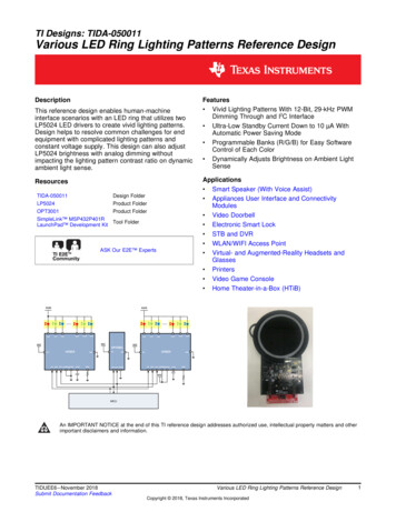
System Overviewwww.ti.comMAP I2C masterSendMultiByteStart(EUSCI B1 BASE, LED Number*3 0x11);//send registeraddressMAP I2C masterSendMultiByteFinish(EUSCI B1 BASE,GS Blue); // send register data}else{MAP I2C setSlaveAddress(EUSCI B1 BASE, SLAVE ADDRESS2);MAP I2C masterSendMultiByteStart(EUSCI B1 BASE, (LED Number8)*3 0x0F); //send register addressMAP I2C masterSendMultiByteFinish(EUSCI B1 BASE,GS Red); // send register dataMAP I2C masterSendMultiByteStart(EUSCI B1 BASE, (LED Number8)*3 0x10); //send register addressMAP I2C masterSendMultiByteFinish(EUSCI B1 BASE,GS Green); // send register dataMAP I2C masterSendMultiByteStart(EUSCI B1 BASE, (LED Number8)*3 0x11); //send register addressMAP I2C masterSendMultiByteFinish(EUSCI B1 BASE,GS Blue); // send register data}}void Reset(){MAP I2C setSlaveAddress(EUSCI B1 BASE, SLAVE ADDRESS);MAP I2C masterSendMultiByteStart(EUSCI B1 BASE, 0x27); //send register addressMAP I2C masterSendMultiByteFinish(EUSCI B1 BASE,0xFF); // send register data}2.4.6.1BreathingFigure 6. LED Current Waveform of BreathingLED CurrentLEDRLEDGLEDB1S2SThe sample code for breathing is as follows:void breath fresh Red(void){Mode Select Normal();Device Config1(1,1,1,1,0,0);LED CONFIG0(1,1,1,1,1,1,1,1);//Bank control set, every LED in BANKBank Brightness Set(0);Bank Color Set(255,0,0);//Bank color R:255 G:0 B:0TIDUEE6 – November 2018Submit Documentation FeedbackVarious LED Ring Lighting Patterns Reference DesignCopyright 2018, Texas Instruments Incorporated11
System Overviewwww.ti.comint i;for(i 0;i 256;i ){Bank Brightness Set U1(i);Bank Brightness Set U2(i);delay ms(5);}for(i 255;i 0;i--){Bank Brightness Set U1(i);Bank Brightness Set U2(i);delay ms(5);}}void breath fresh Green(void){Mode Select Normal();Device Config1(1,1,1,1,0,0);LED CONFIG0(1,1,1,1,1,1,1,1);//Bank control set, every LED in BANKBank Brightness Set(0);Bank Color Set(0,255,0);//Bank color R:0 G:255 B:0int i;for(i 0;i 256;i ){Bank Brightness Set U1(i);Bank Brightness Set U2(i);delay ms(5);}for(i 255;i 0;i--){Bank Brightness Set U1(i);Bank Brightness Set U2(i);delay ms(5);}}void breath fresh Blue(void){Mode Select Normal();Device Config1(1,1,1,1,0,0);LED CONFIG0(1,1,1,1,1,1,1,1);//Bank control set, every LED in BANKBank Brightness Set(0);Bank Color Set(0,0,255);//Bank color R:200 G:0 B:0int i;for(i 0;i 256;i ){Bank Brightness Set U1(i);Bank Brightness Set U2(i);delay ms(5);}for(i 255;i 0;i--){Bank Brightness Set U1(i);Bank Brightness Set U2(i);delay ms(5);}}void breath fresh Yellow(void){Mode Select Normal();Device Config1(1,1,1,1,0,0);LED CONFIG0(1,1,1,1,1,1,1,1);//Bank control set, every LED in BANKBank Brightness Set(0);Bank Color Set(255,255,0);//Bank color R:255 G:255 B:012Various LED Ring Lighting Patterns Reference DesignCopyright 2018, Texas Instruments IncorporatedTIDUEE6 – November 2018Submit Documentation Feedback
System Overviewwww.ti.comint i;for(i 0;i 256;i ){Bank Brightness Set U1(i);Bank Brightness Set U2(i);delay ms(5);}for(i 255;i 0;i--){Bank Brightness Set U1(i);Bank Brightness Set U2(i);delay ms(5);}}void breath fresh Pink(void){Mode Select Normal();Device Config1(1,1,1,1,0,0);LED CONFIG0(1,1,1,1,1,1,1,1);//Bank control set, every LED in BANKBank Brightness Set(0);Bank Color Set(255,0,255);//Bank color R:200 G:0 B:0int i;for(i 0;i 256;i ){Bank Brightness Set U1(i);Bank Brightness Set U2(i);delay ms(5);}for(i 255;i 0;i--){Bank Brightness Set U1(i);Bank Brightness Set U2(i);delay ms(5);}}void breath fresh Teal(void){Mode Select Normal();Device Config1(1,1,1,1,0,0);LED CONFIG0(1,1,1,1,1,1,1,1);//Bank control set, every LED in BANKBank Brightness Set(0);Bank Color Set(0,255,255);//Bank color R:200 G:0 B:0int i;for(i 0;i 256;i ){Bank Brightness Set U1(i);Bank Brightness Set U2(i);delay ms(5);}for(i 255;i 0;i--){Bank Brightness Set U1(i);Bank Brightness Set U2(i);delay ms(5);}}void breath fresh White(void){Mode Select Normal();Device Config1(1,1,1,1,0,0);LED CONFIG0(1,1,1,1,1,1,1,1);//Bank control set, every LED in BANKBank Brightness Set(0);Bank Color Set(255,255,255);//Bank color R:255 G:255 B:255TIDUEE6 – November 2018Submit Documentation FeedbackVarious LED Ring Lighting Patterns Reference DesignCopyright 2018, Texas Instruments Incorporated13
System Overviewwww.ti.comint i;for(i 0;i 256;i ){Bank Brightness Set U1(i);Bank Brightness Set U2(i);delay ms(5);}for(i 255;i 0;i--){Bank Brightness Set U1(i);Bank Brightness Set U2(i);delay ms(5);}}void breath fresh BreathingWithCorlorChanging(void){Mode Select Normal();Device Config1(1,1,1,1,0,0);LED CONFIG0(1,1,1,1,1,1,1,1);//Bank control set, every LED in BANKBank Brightness Set(255);//Bank Color Set(200,0,0);//Bank color R:200 G:0 B:0int i;for(i 0;i 201;i ){Bank Color Set(0,0,i);delay ms(5);}for(i 0;i 256;i ){Bank Color Set(0,i,201);delay ms(5);}for(i 255;i 0;i--){Bank Color Set(0,i,201);delay ms(5);}for(i 0;i 256;i ){Bank Color Set(i,0,201);delay ms(5);}for(i 255;i 0;i--){Bank Color Set(i,0,201);delay ms(5);}for(i 200;i 0;i--){Bank Color Set(0,0,i);delay ms(5);}}14Various LED Ring Lighting Patterns Reference DesignCopyright 2018, Texas Instruments IncorporatedTIDUEE6 – November 2018Submit Documentation Feedback
System Overviewwww.ti.com2.4.6.2Chasing 1Figure 7. LED Current Waveform of Single Color E6 – November 2018Submit Documentation Feedback2SVarious LED Ring Lighting Patterns Reference DesignCopyright 2018, Texas Instruments Incorporated15
System Overviewwww.ti.comThe sample code for the chasing effect is as follows:void ChasingEffectFade Red(void){//Mode Select Normal();//Device Config1(1,1,1,1,0,0);int i;for(i 0;i 16;i ){LED Color Set(i%16,6*(i%16),0,0);LED Color Set((i 1)%16,8*(i%16),0,0);LED Color Set((i 2)%16,10*(i%16),0,0);LED Color Set((i 3)%16,12*(i%16),0,0);LED Color Set((i 4)%16,14*(i%16),0,0);LED Color Set((i 5)%16,16*(i%16),0,0);LED Color Set((i 6)%16,0,0,0);LED Color Set((i 7)%16,0,0,0);LED Color Set((i 8)%16,6*(i%16),0,0);LED Color Set((i 9)%16,8*(i%16),0,0);LED Color Set((i 10)%16,10*(i%16),0,0);LED Color Set((i 11)%16,12*(i%16),0,0);LED Color Set((i 12)%16,14*(i%16),0,0);LED Color Set((i 13)%16,16*(i%16),0,0);LED Color Set((i 14)%16,0,0,0);LED Color Set((i 15)%16,0,0,0);delay ms(32);}for(i 15;i 0;i--){LED Color Set(i%16,6*(i%16),0,0);LED Color Set((i 1)%16,8*(i%16),0,0);LED Color Set((i 2)%16,10*(i%16),0,0);LED Color Set((i 3)%16,12*(i%16),0,0);LED Color Set((i 4)%16,14*(i%16),0,0);LED Color Set((i 5)%16,16*(i%16),0,0);LED Color Set((i 6)%16,0,0,0);LED Color Set((i 7)%16,0,0,0);LED Color Set((i 8)%16,6*(i%16),0,0);LED Color Set((i 9)%16,8*(i%16),0,0);LED Color Set((i 10)%16,10*(i%16),0,0);LED Color Set((i 11)%16,12*(i%16),0,0);LED Color Set((i 12)%16,14*(i%16),0,0);LED Color Set((i 13)%16,16*(i%16),0,0);LED Color Set((i 14)%16,0,0,0);LED Color Set((i 15)%16,0,0,0);delay ms(32);}}16Various LED Ring Lighting Patterns Reference DesignCopyright 2018, Texas Instruments IncorporatedTIDUEE6 – November 2018Submit Documentation Feedback
System Overviewwww.ti.com2.4.6.3Chasing 2Figure 8. LED Current Waveform of Multi Color EDG5LEDG4LEDG3LEDG2LEDG1LEDG0LEDBTIDUEE6 – November 2018Submit Documentation Feedback1S2SVarious LED Ring Lighting Patterns Reference DesignCopyright 2018, Texas Instruments Incorporated17
System Overviewwww.ti.comThe sample code is as follows:void ChasingEffectFade Red(void){//Mode Select Normal();//Device Config1(1,1,1,1,0,0);int i;for(i 0;i 16;i ){LED Color Set(i%16,6*(i%16),0,0);LED Color Set((i 1)%16,8*(i%16),0,0);LED Color Set((i 2)%16,10*(i%16),0,0);LED Color Set((i 3)%16,12*(i%16),0,0);LED Color Set((i 4)%16,14*(i%16),0,0);LED Color Set((i 5)%16,16*(i%16),0,0);LED Color Set((i 6)%16,0,0,0);LED Color Set((i 7)%16,0,0,0);LED Color Set((i 8)%16,6*(i%16),0,0);LED Color Set((i 9)%16,8*(i%16),0,0);LED Color Set((i 10)%16,10*(i%16),0,0);LED Color Set((i 11)%16,12*(i%16),0,0);LED Color Set((i 12)%16,14*(i%16),0,0);LED Color Set((i 13)%16,16*(i%16),0,0);LED Color Set((i 14)%16,0,0,0);LED Color Set((i 15)%16,0,0,0);delay ms(32);}for(i 15;i 0;i--){LED Color Set(i%16,6*(i%16),0,0);LED Color Set((i 1)%16,8*(i%16),0,0);LED Color Set((i 2)%16,10*(i%16),0,0);LED Color Set((i 3)%16,12*(i%16),0,0);LED Color Set((i 4)%16,14*(i%16),0,0);LED Color Set((i 5)%16,16*(i%16),0,0);LED Color Set((i 6)%16,0,0,0);LED Color Set((i 7)%16,0,0,0);LED Color Set((i 8)%16,6*(i%16),0,0);LED Color Set((i 9)%16,8*(i%16),0,0);LED Color Set((i 10)%16,10*(i%16),0,0);LED Color Set((i 11)%16,12*(i%16),0,0);LED Color Set((i 12)%16,14*(i%16),0,0);LED Color Set((i 13)%16,16*(i%16),0,0);LED Color Set((i 14)%16,0,0,0);LED Color Set((i 15)%16,0,0,0);delay ms(32);}}18Various LED Ring Lighting Patterns Reference DesignCopyright 2018, Texas Instruments IncorporatedTIDUEE6 – November 2018Submit Documentation Feedback
System Overviewwww.ti.com2.4.6.4Chasing 3Figure 9. Current Wave of Custom E6 – November 2018Submit Documentation Feedback2SVarious LED Ring Lighting Patterns Reference DesignCopyright 2018, Texas Instruments Incorporated19
System Overviewwww.ti.comThe sample code is as follows:void ChasingEffect Custom(void){//Mode Select Normal();//Device Config1(1,1,1,1,0,0);int i;for(i 0;i 16;i ){LED Color Set(i%16,103,103,0);LED Color Set((i 1)%16,193,193,0);LED Color Set((i 2)%16,233,233,0);LED Color Set((i 3)%16,0,0,200);LED Color Set((i 4)%16,0,0,200);LED Color Set((i 5)%16,0,0,200);LED Color Set((i 6)%16,0,0,200);LED Color Set((i 7)%16,0,0,200);LED Color Set((i 8)%16,0,70,12);LED Color Set((i 9)%16,0,121,25);LED Color Set((i 10)%16,0,252,50);LED Color Set((i 11)%16,0,0,200);LED Color Set((i 12)%16,0,0,200);LED Color Set((i 13)%16,0,0,200);LED Color Set((i 14)%16,0,0,200);LED Color Set((i 15)%16,0,0,200);delay ms(30);}}20Various LED Ring Lighting Patterns Reference DesignCopyright 2018, Texas Instruments IncorporatedTIDUEE6 – November 2018Submit Documentation Feedback
System Overviewwww.ti.com2.4.6.5Water DropFigure 10. Current Wave of Water DropLEDR14/15LEDR12/13LED
Various LED Ring Lighting Patterns Reference Design 1 System Description This is the design guide for the Various LED Ring Lighting Patterns Reference Design, which makes the vivid lightings pattern on