Transcription
W124 Diagnostic Trouble Codes (DTC) – Models with M119 Engine Only!The pages in this document have the Diagnostic Trouble Codes (DTC’s) for the following models:1990-1993 400E & 500E (4.2L and 5.0L M119.97x engines)1994-1995 E420, E500, E60 AMG (4.2L, 5.0L, & 6.0L M119.97x engines)The chassis covered are:124.034 (Sedan with 4.2L M119.975 engine)124.036 (Sedan with 5.0L M119.974 engine)124.036 (Sedan with 6.0L M119.974 engine, option code 957, E60 AMG)The diagnostic connector has 38 pins total, please see the next several pages which explain thespecifics of each pin. Note that not all pins are used. Also, for the 400E / E420 (124.034), ASR tractioncontrol was optional. The DTC’s are slightly different between models with ABS only (no ASR), andmodels with both ABS and ASR. Please make sure you are using the correct sheets when looking upcodes for ABS/ ASR, and the EA/CC/ISC systems! All 500E / E500 / E60 models (124.036) camestandard with both ABS and ASR. Models without ASR (124.034 only) have a CC/ISC (Cruise Control / Idle Speed Control) module,N4/3, which controls the CC/ISC actuator (M16/2). The ABS control module is N30. Models with ASR have an EA/CC/ISC (Electronic Accelerator / Cruise Control / Idle SpeedControl) module, N4/1, which controls the EA/CC/ISC actuator (M16/1). The ABS/ASR controlmodule is N30/1.All systems have analog “blink codes” available, which can be read with the factory impulse countertool, or a home-made “LED light box”. However, the digital 3-digit codes are more specific than theanalog 1- or 2-digit codes, particularly for the E-GAS module (pin #7). To access digital 3-digit codes, aMercedes digital scanner is required, such as the HHT (Hand Held Tester) or SDS (Star DiagnosisSystem); or an aftermarket digital scan tool (such as the Snap-On MT2500, Modis, or Solus; or TriscoPalm Scan). Some systems only have analog blink codes available (i.e., the ACC and SRS systems) these systems do not offer any digital communication.The Check Engine Light (CEL) may only be present on models with California emissions. Only thesemodels will have a Diagnostic Module (DM). DM codes can be read using the built-in pushbutton & LEDat the 8-pin connector in front of the CAN box, near the 38-pin connector. ONLY codes from the DM willshow using the built-in LED, you cannot read codes from the LH, ABS, ASR, E-GAS, etc from this LED.
This document includes the complete list of DTC’s for the following systems:Pin #4 – LH-SFI (LH Sequential Fuel Injection)(WIS Group 07.41, subgroup 3.1, section #11, five pages)Pin #6 - ABS (Anti-lock Brake System) - For models without ASR(WIS Group 42.30, subgroup 6.2, section #11, one page)Pin #6 - ABS / ASR (Anti-lock Brake System / ASR) - For models with ASR traction control(WIS Group 42.40, subgroup 5.2, section #12, two pages)Pin #7 - CC/ISC (Cruise Control / Idle Speed Control) - For models without ASR(WIS Group 30.21, subgroup 6.2, section #11, two pages) – aka “E-GAS Module”Pin #7 - EA/CC/ISC (Electronic Accelerator / CC / ISC) - For models with ASR traction control(WIS Group 30.20, subgroup 6.2, section #11, two pages) – aka “E-GAS Module”Pin #8 - Base Module (Power supply for the other modules – has 4 fuses on top) – aka “Basic Module”(WIS Group 54.21, subgroup 1.1, section #11, one page)Pin #16 - ACC (Automatic Climate Control) – Only blink codes available(WIS Group 83.40, subgroup 0603, section B, four pages)Pin #17 - EZL (Digital Ignition System)(WIS Group 07.41, subgroup 5.2, section #11, two pages)Pin #19 - Diagnostic Module (CA models only – will also have LED pushbutton in front of CAN box)(WIS Group 07.41, subgroup 8.1, section #11, one page)Pin #30 - Airbag / SRS (Supplemental Restraint System) - Only blink codes available(WIS Group 91.60, subgroup 16.1, section 12, one page)
Diagnosis - Diagnostic Trouble Code (DTC) MemoryPreliminary work:Engine Test and Adjustment, Engines, Volume 1LH Fuel Injection(Pin #4)If a malfunction is no longer present during a subsequent engine start orengine operation, the total value recorded by the malfunction counter isreduced by 1 every time the engine is switched off. This procedure repeatsitself until the malfunction counter is cleared.On-Off Ratio TestThe on-off ratio tests the operation of the O2S (Lambda) control system andadditionally, recognizes certain malfunctions present during the test.Malfunctions are distinguished between those that occur with theIgnition: ON and those that occur with the Engine: at CTP (idle).The on-off ratio can be checked with the on-off ratio tester or with the engineanalyzer. For this purpose, the purge line to the engine must be disconnectedat the purge control valve and closed with a plug. Check on-off ratio at closedthrottle speed and at 2500 rpm. A readout of 50% or an oscillating needleindicates that all input signals and the O2S control system are OK. Readoutsof 10% to 90% or 95% refer to a particular malfunction source (seeMalfunction Tables). In addition, after testing the on-off ratio, an impulsereadout must be performed using the impulse counter scan tool.Stored malfunctions (DTC s) can be read with the impulse counter scan toolat the data link connector (X11/4). (Also see DM, Engines, Volume 2, section5.)Diagnostic Trouble Code (DTC) Readout with Impulse Counter ScanTool.Malfunctions which occur while starting or with the engine running arerecorded by a malfunction counter. Malfunctions are assigned a specific valueaccording to malfunction severity (e.g. hot wire MAF sensor 128, ECT sensor32). The malfunction counter counts in stages up to a threshold value of 255.After reaching the threshold value of 128, intermittent malfunctions are storedinto memory after switching off the ignition. Malfunctions which affect engineoperation ( 128) are immediately stored into DTC memory by themalfunction counter after switching off the ignition.A malfunction of the following is stored after more than 2 trips:TN-signal (input).The DTC memory readout must be performed with the engine OFF and theignition switched ON.Malfunctions occurring in the following areas are stored immediately:CMP sensor,Hot-wire MAF sensor,Injectors.The memory remains active even if the vehicle's battery is disconnected.Diagnosis - Diagnostic Trouble Code (DTC) MemoryDTC's can be read with the impulse counter scan tool. Numbers ranging from1 to 32 may appear on the display of the impulse counter scan tool.The number 1 indicates: No DTC recognized in system.All further numbers refer to a particular malfunction source. If there aremultiple system malfunctions, the malfunction assigned with the lowestnumber will be displayed first.If the DTC number indicated first reappears after more than two DTCreadouts, then no further malfunctions are stored in the system's memory.After eliminating all malfunctions, they must be cleared individually and theignition must be switched off for a minimum of 15 seconds.In case of engine running complaints, the DTC memory must be read and themalfunction must be eliminated before proceeding with any additional repairs.After eliminating the mentioned malfunctions or after trial installation of a LHSFI control module from another vehicle, the LH-SFI control module's selfadaptation feature must be reset to its mean value (see Resetting LH-SFIControl Module's Self-Adaptation Feature to Mean Value"11/4 or with HHTmenu selection 5 Self-Adaptation ).The LH-SFI control module will also adapt itself during the course of vehicleoperation.LH-SFI Control Module Self-Adaptation FeatureA self-adaptation feature for the emission control system is incorporated intothe LH-SFI control module.If malfunctions of the:Hot-wire MAF sensor,Injectors,Purge control valve,Diaphragm pressure regulator,Purge valveoccur or if intake air leaks are present, the LH-SFI control module conducts aself-adaptation process whereby the correction factors are continuouslycalculated and permanently stored.Diagnosis - Diagnostic Trouble Code (DTC) MemoryCopyright Daimler AG 11/3/08 G/06/08. This WIS printout will not be recorded by the update service.Page 1
Notes for HHTFault search with HHT.Diagnostic trouble code (DTC) memory: SelectLH Fuel Injection(Pin #4)Current DTC's".If the actual condition changes, e.g. when wiggling a connector, thechange is reported optically and acoustically so that troubleshootingcan be performed directly with the HHT.Loose connections.Loose connections are stored if they occur several times in a certaintime period. Therefore, they can appear only asnever asStored DTC's" andCurrent DTC's".Nominal values.All nominal values relative to the actual values as shown on the HHTare listed in the DM, Engines, Volume 1, section A.Actual values for ECT, IAT and MAF.In case of an open or short circuit, the actual value is immediatelyreplaced by a substitute value which is very close to the actual value.Therefore, a fault can not be recognized clearly. A readout of the faultis possible only via the diagnostic trouble code (DTC) memory.Actual value for engine rpm.In case of the engine rpm's, the HHT display shows the closed throttle(idle) speed nominal value calculated by the control module on the left,and on the right, the rpm actual value. Both values should differ fromeach other only slightly. The permissible tolerances are not known.Diagnosis - Diagnostic Trouble Code (DTC) MemoryPreparation for Test with Impulse Counter Scan ToolConnect impulse counter scan tool and on-off ratio tester according toconnection diagram.Reading Diagnostic Trouble Code (DTC) Memorya)Ignition: ONb)Press start button for 2 to 4 seconds.c)Read and record DTC readout.d)Press start button again for 2 to 4 seconds.e)Read and record DTC readout.Repeat steps d) and e) until the first DTC reappears.Clearing Diagnostic Trouble Code (DTC) Memorya)Press start button for 2 to 4 seconds (DTC readout appears).b)Wait 3 seconds, press start button for 6 to 8 seconds, thereby clearingthe previously displayed DTC from memory.c)Each stored DTC must be cleared individually.d)Ignition: OFF and wait 15 seconds.Check if all stored DTC's are eliminated.e)Ignition: ONf)Repeat DTC readout. The number" (no DTC stored) must appear.Resetting LH-SFI Control Module's Self-Adaptation Feature to MeanValueAfter the number" appears on the display, press start button for 6 to 8seconds.Ignition: OFF and wait 30 seconds.Diagnosis - Diagnostic Trouble Code (DTC) MemorySpecial Tools124 589 19 21 00140 589 14 63 00965 589 00 01 00965 589 00 40 00909 589 09 21 00Diagnosis - Diagnostic Trouble Code (DTC) MemoryCopyright Daimler AG 11/3/08 G/06/08. This WIS printout will not be recorded by the update service.Page 2
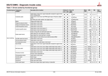
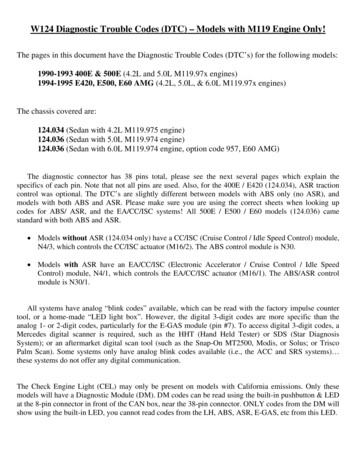
Connection Diagram - Impulse Counter Scan Tooland On-Off Ratio Tester or Engine Analyzer withDiagnostic Socket X11Note:Connect red wire of impulse counter scan tool tosocket 3, black wire of impulse counter scan toolto socket 1, yellow wire of impulse counter scan toolas follows:LH-SFI control moduleSocket 4DI control moduleSocket 17Base moduleSocket 8EA/CC/ISC control moduleSocket 7Diagnostic moduleSocket 19LH Fuel Injection(Pin #4)Figure 1012013075X11X11/4On-off ratio testerImpulse counter scan toolImpulse counter scan tool adaptorDiagnostic socket (9-pole)Data link connector (DTC readout)U07-5004-57Diagnosis - Diagnostic Trouble Code (DTC) MemoryConnection Diagram - Impulse Counter Scan Tool/Hand-Held Tester and On-Off Ratio Testerwithout Diagnostic Socket X11Note:Connect red wire of impulse counter scan tool tosocket 3, black wire of impulse counter scan toolto socket 1, yellow wire of impulse counter scan toolas follows:LH-SFI control moduleSocket 4Base moduleSocket 8EA/CC/ISC control moduleSocket 7Diagnostic moduleSocket 19RPM signal (TN output)Socket 13On-off ratio readoutSocket 14Circuit 31Socket 1Circuit 30Socket 3Figure 2012013034075087094X11/4On-off ratio testerImpulse counter scan toolTest cableRed alligator clip to socket 3Black alligator clip to socket 1Black male plug to socket 14Green male plug not connectedYellow male plug not connectedImpulse counter scan tool adaptorHand-Held Tester (optional with impulsecounter scan toolMultiplex cableData link connector (DTC readout)U07-6491-57Diagnosis - Diagnostic Trouble Code (DTC) Memorya) On-Off Ratio Test, Ignition: ONOn-Off Ratio %Possible causeTest step/Remedy 1)Voltage supply from socket 3 of data link connector (X11/4) open circuitRepair harnessCTP (idle) recognition inactive2315.0WOT (full load) recognition active2315.0239.0, 10.0TN-signal (rpm signal) or CMP sensor signal not present while starting2312.0 - 14.0Starter engaged238.1CAN-data exchange defective2339.0Engine coolant temperature 70oC or 110oCNot usedInput signals OKCopyright Daimler AG 11/3/08 G/06/08. This WIS printout will not be recorded by the update service.Page 3
Fuel safety shut-off active1)Observe Preparation for Test, seeCheck CC/ISC (see DM, Engines,Volume 3, Section 7.1)orCheck EA (see DM, Engines,Volume 3, Section 6.2)22.LH Fuel Injection(Pin #4)Diagnosis - Diagnostic Trouble Code (DTC) Memoryb) On-Off Ratio Test, Engine: at CTP (idle)On-Off Ratio %Possible causeTest step/Remedy 1)Short circuit to battery in wire to data link connector (X11/4), socket 3Repair harnessCTP (idle) recognition applied constantly2)232332.0, 33.0ECT sensor (B11/2)239.0, 10.1Hot wire MAF sensor (B2/2)235.0, 6.0O2S 1 (before TWC) (G3/2) not operational or defective, open circuit2318.0 - 19.1CMP sensor (L5/1)2314.0TN-signal (rpm signal)2312.0, 13.0CAN-data exchange defective1)2)15.0Output of fuel injectors orone or more fuel injectors have open circuit2339.0 - 40.0Either EA/CC/ISC control module, CC/ISC control module or DI control modulenot transmitting.Observe Preparation for Test, see22.Needle oscillates if all monitored signals are OK.Diagnosis - Diagnostic Trouble Code (DTC) Memoryb)On-Off Ratio Test, Engine: at CTP (idle)On-off Ratio %Possible causeTest step/Remedy 1)Vehicle speed signal (VSS)Check CC/ISC (see DM, Engines,Volume 3, section 7.1)
W124 Diagnostic Trouble Codes (DTC) – Models with M119 Engine Only! The pages in this document have the Diagnostic Trouble Codes (DTC’s) for the following models: 1990-1993 400E & 500E (4.2L and 5.0L M119.97x engines) 1994-1995 E420, E500, E60 AMG (4.2L, 5.0L, & 6.0L M119.97x engines) The chassis covered are:File Size: 880KBPage Count: 25