Transcription
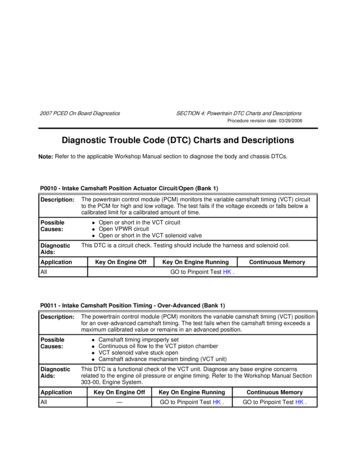
2007 PCED On Board DiagnosticsSECTION 4: Powertrain DTC Charts and DescriptionsProcedure revision date: 03/29/2006Diagnostic Trouble Code (DTC) Charts and DescriptionsNote: Refer to the applicable Workshop Manual section to diagnose the body and chassis DTCs.P0010 - Intake Camshaft Position Actuator Circuit/Open (Bank 1)Description:PossibleCauses:The powertrain control module (PCM) monitors the variable camshaft timing (VCT) circuitto the PCM for high and low voltage. The test fails if the voltage exceeds or falls below acalibrated limit for a calibrated amount of time. DiagnosticAids:Open or short in the VCT circuitOpen VPWR circuitOpen or short in the VCT solenoid valveThis DTC is a circuit check. Testing should include the harness and solenoid coil.ApplicationKey On Engine OffAllKey On Engine RunningContinuous MemoryGO to Pinpoint Test HK .P0011 - Intake Camshaft Position Timing - Over-Advanced (Bank 1)Description:PossibleCauses:The powertrain control module (PCM) monitors the variable camshaft timing (VCT) positionfor an over-advanced camshaft timing. The test fails when the camshaft timing exceeds amaximum calibrated value or remains in an advanced position. DiagnosticAids:ApplicationAllCamshaft timing improperly setContinuous oil flow to the VCT piston chamberVCT solenoid valve stuck openCamshaft advance mechanism binding (VCT unit)This DTC is a functional check of the VCT unit. Diagnose any base engine concernsrelated to the engine oil pressure or engine timing. Refer to the Workshop Manual Section303-00, Engine System.Key On Engine OffKey On Engine RunningContinuous Memory—GO to Pinpoint Test HK .GO to Pinpoint Test HK .
P0012 - Intake Camshaft Position Timing - Over-Retarded (Bank 1)Description:PossibleCauses:The powertrain control module (PCM) monitors the variable camshaft timing (VCT) positionfor over-retarded camshaft timing. The test fails when the camshaft timing exceeds amaximum calibrated value or remains in a retarded position. DiagnosticAids:ApplicationCamshaft timing improperly setContinuous oil flow to the VCT piston chamberVCT solenoid valve stuck openCamshaft advance mechanism binding (VCT unit)This DTC is a functional check of the VCT unit. Diagnose any base engine concernsrelated to the engine oil pressure or engine timing. Refer to the Workshop Manual Section303-00, Engine System.Key On Engine OffKey On Engine RunningContinuous Memory—GO to Pinpoint Test HK .GO to Pinpoint Test HK .AllP0016 - Crankshaft Position - Camshaft Position Correlation - Bank 1 Sensor ADescription:PossibleCauses:The powertrain control module (PCM) monitors the variable camshaft timing (VCT)position for a misalignment between the camshaft and crankshaft. The test fails when themisalignment is greater than 1 tooth. DiagnosticAids:ApplicationAllWorn timing chain tensionerWorn timing chain tensioner armLoose timing chainCheck or adjust the timing.Key On Engine OffKey On Engine RunningContinuous MemoryRefer to the Workshop Manual Section 303-01, Engine, to verify the timing.P0018 - Crankshaft Position - Camshaft Position Correlation - Bank 2 Sensor ADescription:See the description for DTC P0016.Possible Causes: See the possible causes for DTC P0016.Diagnostic Aids: See the diagnostic aids for DTC P0016.ApplicationAllKey On Engine OffKey On Engine RunningContinuous MemoryRefer to the Workshop Manual Section 303-01, Engine, to verify the timing.
P0020 - Intake Camshaft Position Actuator Circuit/Open (Bank 2)Description:See the description for DTC P0010.Possible Causes: See the possible causes for DTC P0010.Diagnostic Aids: See the diagnostic aids for DTC P0010.ApplicationKey On Engine Off Key On Engine Running Continuous MemoryAllGO to Pinpoint Test HK .P0021 - Intake Camshaft Position Timing - Over-Advanced (Bank 2)Description:See the description for DTC P0011.Possible Causes: See the possible causes for DTC P0011.Diagnostic Aids: See the diagnostic aids for DTC P0011.ApplicationAllKey On Engine Off Key On Engine Running—Continuous MemoryGO to Pinpoint Test HK . GO to Pinpoint Test HK .P0022 - Intake Camshaft Position Timing - Over-Retarded (Bank 2)Description:See the description for DTC P0012.Possible Causes: See the possible causes for DTC P0012.Diagnostic Aids: See the diagnostic aids for DTC P0012.ApplicationAllKey On Engine Off Key On Engine Running—Continuous MemoryGO to Pinpoint Test HK . GO to Pinpoint Test HK .P0040 - Oxygen Sensor Signals Swapped Bank 1 Sensor 1/Bank 2 Sensor 1Description:The heated oxygen sensor (HO2S) monitor determines if the HO2S signal response for afuel shift corresponds to the correct engine bank. The test fails when there is no responsefrom the HO2S being tested.
PossibleCauses:Crossed HO2S harness connectorsCrossed HO2S wiring at the harness connectorsCrossed HO2S wiring at the PCM connectors DiagnosticAids:Connect the HO2S connector to the correct bank.ApplicationKey On Engine OffKey On Engine RunningContinuous Memory—GO to Pinpoint Test DW .—AllP0041 - Oxygen Sensor Signals Swapped Bank 1 Sensor 2/Bank 2 Sensor 2Description:PossibleCauses:The heated oxygen sensor (HO2S) monitor determines if the HO2S signal response for afuel shift corresponds to the correct engine bank. The test fails when there is no responsefrom the HO2S being tested.Crossed HO2S harness connectorsCrossed HO2S wiring at the harness connectorsCrossed HO2S wiring at the PCM connectors DiagnosticAids:ApplicationConnect the HO2S connector to the correct bank.Key On Engine OffKey On Engine RunningContinuous Memory—GO to Pinpoint Test DW .—AllP005x - HO2S Heater Resistance (Bank 1, Sensor 1), (Bank 1, Sensor 2), (Bank 1, Sensor 3), and(Bank 2, Sensor 1)Description:PossibleCauses:Heater current requirements too low or high in the heated oxygen sensor (HO2S) heatercontrol circuit (HO2S11, HO2S12, HO2S13, HO2S21). DiagnosticAids:ApplicationAllVPWR circuit openHO2S heater circuit openHO2S heater circuit short in the harnessDamaged HO2S heaterInspect the connectors for signs of damage, water ingress, or corrosion.Key On Engine OffKey On Engine RunningGO to Pinpoint Test DW .Continuous Memory
P0060 - HO2S Heater Resistance (Bank 2, Sensor 2)Description:Heater current requirements too low or high in the heated oxygen sensor (HO2S) heatercontrol circuit (HO2S22).PossibleCauses:See the possible causes for DTC P005x.DiagnosticAids:See the diagnostic aids for DTC P005x.ApplicationKey On Engine OffAllKey On Engine RunningContinuous MemoryGO to Pinpoint Test DW .P0068 - Manifold Absolute Pressure (MAP)/Mass Air Flow (MAF) - Throttle Position CorrelationThe powertrain control module (PCM) monitors a vehicle operation rationality check bycomparing sensed throttle position to mass air flow readings. If during a key on enginerunning (KOER) self-test, the comparison of the throttle position (TP) sensor and MAFsensor readings are not consistent with the calibrated load values, the test fails and aDTC is stored in continuous memory.Description:PossibleCauses: Air leak between MAF sensor and throttle bodyTP sensor not seated properlyDamaged TP sensorDamaged MAF sensorDiagnostic Aids: Diagnose any MAP, MAF, or TP circuit DTCs first. Drive the vehicle and exercise thethrottle and the TP sensor in all gears. A TP PID less than 4.82% (0.24 volt) with aLOAD PID greater than 55%, or a TP PID greater than 49.05% (2.44 volts) with aLOAD PID less than 30% indicates a concern is present.ApplicationKey On Engine OffKey On Engine RunningContinuous MemoryVehicles WithElectronic ThrottleControl (ETC)—GO to Pinpoint Test DV .GO to Pinpoint Test DV .All others—GO to Pinpoint Test DH .GO to Pinpoint Test DH .P0097 - Intake Air Temperature Sensor 2 Circuit LowDescription:Indicates the sensor signal is less than the self-test minimum. The intake air temperature2 (IAT2) sensor minimum is 0.2 volt.
PossibleCauses: DiagnosticAids:Grounded circuit in the harnessIncorrect harness connectionDamaged sensorMonitor the IAT2 PID value. A typical IAT2 temperature should be greater than the IAT1temperature. Refer to Section 6 , Reference Values.ApplicationKey On Engine OffKey On Engine RunningAllContinuous MemoryGO to Pinpoint Test DU .P0098 - Intake Air Temperature Sensor 2 Circuit HighDescription:Indicates the sensor signal is greater than the self-test maximum. The intake airtemperature 2 (IAT2) sensor maximum is 4.6 volts.PossibleCauses: DiagnosticAids:Open circuit in the harnessSensor signal short to voltageIncorrect harness connectionDamaged sensorMonitor the IAT2 PID value. A typical IAT2 temperature should be greater than the IAT1temperature. Refer to Section 6 , Reference Values.ApplicationKey On Engine OffKey On Engine RunningAllContinuous MemoryGO to Pinpoint Test DU .P0102 - Mass or Volume Air Flow A Circuit LowDescription: The mass air flow (MAF) sensor circuit is monitored by the powertrain control module(PCM) for low air flow (or voltage) input through the comprehensive component monitor(CCM). If during key on, engine running (KOER) the air flow (or voltage) changes below aminimum calibrated limit, the test fails.PossibleCauses: DiagnosticAids:MAF sensor disconnectedMAF circuit open to PCMVPWR open to MAF sensorPWR GND open to the MAF sensorMAF RTN circuit open to PCMMAF circuit shorted to GNDIntake air leak (near the MAF sensor)A closed throttle indication (throttle position [TP] sensor system)Damaged MAF sensorA MAF V PID reading less than 0.23 volt in continuous memory or KOER indicates a hardfault.
ApplicationKey On Engine OffKey On Engine RunningContinuous Memory—GO to Pinpoint Test DC .GO to Pinpoint Test DC .AllP0103 - Mass or Volume Air Flow A Circuit HighDescription: The mass air flow (MAF) sensor circuit is monitored by the powertrain control module(PCM) for high air flow (or voltage) input through the comprehensive component monitor(CCM). If during key on, engine off (KOEO), or key on, engine running (KOER), the air flow(or voltage) changes above a maximum calibrated limit, the test fails.PossibleCauses: DiagnosticAids:ApplicationMAF sensor screen is blockedMAF circuit shorted to voltageDamaged MAF sensorA MAF V PID (MAF PID) reading greater than 4.6 volts during KOER indicates a hard fault.Key On Engine OffAllKey On Engine RunningContinuous MemoryGO to Pinpoint Test DC .P0104 - Mass or Volume Air Flow A Circuit gnosticAids:ApplicationA concern exists in the mass air flow (MAF) sensor A circuit, or the air tube containing thesensor, causing an incorrect air flow reading. Intermittent circuit A open or shortAir leaks in the tube from the MAF to the throttle bodyVerify the integrity of the MAF sensor circuit A for an intermittent concern. Check theMAF sensor tube for air leaks.Key On Engine OffKey On Engine RunningContinuous Memory—GO to Pinpoint Test DC .GO to Pinpoint Test DC .AllP0106 - Manifold Absolute Pressure (MAP/BARO) Sensor Range/PerformanceDescription:PossibleCauses:MAP sensor input to the powertrain control module (PCM) is monitored and is not withinthe calibrated value. Slow responding MAP sensorElectrical circuit failure
Damaged MAP sensor DiagnosticAids:VREF voltage should be between 4.0 and 6.0 volts. The PID reading is in frequency.ApplicationKey On Engine OffAllKey On Engine RunningContinuous MemoryGO to Pinpoint Test DM .P0107 - Manifold Absolute Pressure (MAP)/Barometric Pressure (BARO) Sensor LowDescription:MAP sensor operating voltage is below the minimum calibrated parameter of 0.25volts.PossibleCauses: Open in the circuit, or short to groundVREF circuit open, or short to groundDamaged MAP sensorDiagnostic Aids: VREF should be greater than 4.0 volts. The PID reading is in frequency/volts.ApplicationKey On Engine OffAllKey On Engine RunningContinuous MemoryGO to Pinpoint Test DM .P0108 - Manifold Absolute Pressure (MAP)/Barometric Pressure (BARO) Sensor HighDescription:PossibleCauses:Sensor operating voltage is greater than 5 volts (VREF). As a result it failed above themaximum allowable calibrated parameter. DiagnosticAids:ApplicationAllVREF shorted to VPWRMAP signal shorted to VPWRVREF should be less than 6.0 volts. The PID reading is in frequency/voltsOpen circuitVREF should be greater than 4.0 volts. The PID reading is in frequency/volts.Key On Engine OffKey On Engine RunningContinuous MemoryGO to Pinpoint Test DM .P0109 - Manifold Absolute Pressure (MAP)/Barometric Pressure (BARO) Sensor IntermittentDescription:The sensor signal to the powertrain control module (PCM) is failing intermittently.
Possible Causes: Loose electrical connectionDamaged MAP sensorDiagnostic Aids: Check the harness and connection.ApplicationAllKey On Engine OffKey On Engine RunningContinuous MemoryGO to Pinpoint Test DM .——P0111 - Intake Air Temperature (IAT) Sensor 1 Circuit sticAids:ApplicationIndicates the IAT rationality test has failed. This DTC indicates that the IAT value is higherthan a calibrated value and could prevent 1 or more on-board diagnostic (OBD) monitorsfrom completing.The PCM runs this logic after an engine off and a calibrated soak period (typically 6 hours).This soak period allows IAT and engine coolant temperature (CHT or ECT) to stabilize andnot differ by more than a calibrated value. DTC P0111 is set when:the IAT at engine start exceeds the ECT or CHT by more than a calibrated value, typically17 C (30 F). IAT SensorMake sure the IAT and the CHT or ECT are similar when the engine is cold.Key On Engine OffAllKey On Engine RunningContinuous MemoryGO to Pinpoint Test DA .P0112 - Intake Air Temperature (IAT) Sensor 1 Circuit LowDescription:PossibleCauses:Indicates the sensor signal is less than the self-test minimum. The IAT sensor minimumis 0.2 volt or 121 C (250 F). DiagnosticAids:ApplicationAllGrounded circuit in the harnessDamaged sensorImproper harness connectionAn IAT V PID reading less than 0.2 volt with key ON engine OFF or during any engineoperating mode indicates a concern is present.Key On Engine OffKey On Engine RunningGO to Pinpoint Test DA .Continuous Memory
P0113 - Intake Air Temperature (IAT) Sensor 1 Circuit HighDescription:PossibleCauses:Indicates the sensor signal is greater than the self-test maximum. The IAT sensormaximum is 4.6 volts or -50 C (-58 F).Open circuit in the harnessSensor signal short to voltageDamaged sensorImproper harness connection DiagnosticAids:ApplicationAn IAT V PID reading greater than 4.6 volts with the key ON engine OFF or during anyengine operating mode indicates a concern is present.Key On Engine OffAllKey On Engine RunningContinuous MemoryGO to Pinpoint Test DA .P0114 - Intake Air Temperature (IAT) Sensor 1 icates the sensor signal was intermittent during the comprehensive componentmonitor (CCM). DiagnosticAids:ApplicationAllDamaged harnessDamaged sensorDamaged harness connectorMonitor the IAT on a scan tool. Look for sudden changes in the reading when theharness is wiggled or the sensor is tapped.Key On Engine OffKey On Engine RunningContinuous MemoryGO to Pinpoint Test DA .P0116 - Engine Coolant Temperature (ECT) Sensor 1 Circuit Range/PerformanceDescription:Indicates the engine coolant temperature rationality test has failed. This DTC indicatesthat the ECT or cylinder head temperature (CHT) value is higher than the calibratedvalue and could prevent 1 or more on-board diagnostic (OBD) monitors fromcompleting.The PCM runs this logic after an engine off and a calibrated soak period (typically 6hours). This soak period allows the intake air temperature (IAT) and the CHT or ECT tostabilize and not differ by more than a calibrated value. DTC P0116 is set when all of thefollowing conditions are met:The ECT at engine start exceeds the IAT at engine start by more than a calibratedvalue, typically 17 C (30 F).
The ECT exceeds a calibrated value, typically 107 C (225 F).The fuel system, heated oxygen and misfire monitors have not completed.The calibrated time to set DTC P0116 has expired.PossibleCauses:DiagnosticAids: ECT or CHT sensorCoolant system concernMake sure the IAT and the ECT are similar when the engine is cold. Also make sure theECT or CHT sensor and the actual engine operating temperatures are the same.ApplicationKey On Engine OffKey On Engine RunningContinuous MemoryVehicles withonly a CHTsensor——GO to Pinpoint Test DL .All others——GO to Pinpoint Test DX .P0117 - Engine Coolant Temperature (ECT) Sensor 1 Circuit LowDescription:PossibleCauses:Indicates the sensor signal is less than the self-test minimum. The ECT sensor minimumis 0.2 volt or 121 C (250 F). DiagnosticAids:Grounded circuit in the harnessDamaged sensorIncorrect harness connectionA concern is present if an ECT V PID reading less than 0.2 volt with the key ON engineOFF or during any engine operating mode.ApplicationKey On Engine OffAllKey On Engine RunningContinuous MemoryGO to Pinpoint Test DX .P0118 - Engine Coolant Temperature (ECT) Sensor 1 Circuit HighDescription:PossibleCauses:Indicates the sensor signal is greater than the self-test maximum. The ECT sensormaximum is 4.6 volts or -50 C (-58 F). DiagnosticAids:ApplicationOpen circuit in the harnessSensor signal short to voltageImproper harness connectionDamaged sensorAn ECT V PID reading greater than 4.6 volts with the key ON engine OFF or during anyengine operating mode indicates a concern is present.Key On Engine OffKey On Engine RunningContinuous Memory
AllGO to Pinpoint Test DX .P0119 - Engine Coolant Temperature (ECT) Sensor 1 Circuit icates the ECT circuit became intermittently open or shorted while the engine wasrunning. On vehicles that are not equipped with an ECT sensor, the cylinder headtemperature (CHT) sensor can be used and can set this DTC. Damaged harnessDamaged sensorDamaged harness connectorLow engine coolantDiagnostic Aids: Monitor the ECT or the CHT on a scan tool, look for sudden changes in the readingwhen the harness is wiggled or the sensor is tapped.ApplicationKey On Engine OffKey On Engine RunningContinuous MemoryVehicles with onlya CHT sensor——GO to Pinpoint Test DL .All others——GO to Pinpoint Test DX .P0121 - Throttle/Pedal Position Sensor A Circuit Range/PerformanceFor Vehicles With Electronic Throttle Control (ETC)Description:PossibleCauses:The electronic throttle control (ETC) throttle position (TP) sensor 1 circuit was flaggedas a concern by the powertrain control module (PCM) indicating an out of range ineither the closed or wide open throttle (WOT) modes. Obstruction in the throttle plate movementDamaged throttle bodyTP circuit open to PCMDamaged TP sensorSIG RTN circuit open to the TP sensorDiagnostic Aids: This concern exhibits a symptom of limited power. A TP1 PID reading less than 13%(0.65 volt), or greater than 93% (4.65 volts) in key ON, engine OFF or key ON, enginerunning indicates a concern is present.For All OthersDescription:The throttle position (TP) sensor circuit is monitored by the powertrain control module(PCM) for a non-closed throttle position at idle. The test fails if the key on enginerunning (KOER) self-test terminates upon placing the transmission gear selector inDRIVE or REVERSE or the TP closed throttle position is not achieved when closing the
throttle (idle) after opening it (in PARK or NEUTRAL).PossibleCauses: Binding throttle linkageDamaged throttle bodyTP circuit open to PCMDamaged TP sensorSIG RTN circuit open to the TP sensorDiagnostic Aids: Drive the vehicle, bring it to a stop, and turn the key to the OFF position. Start thevehicle, and run the KOER self-test at idle.ApplicationKey On Engine OffKey On Engine RunningVehicles WithElectronic ThrottleControl (ETC)GO to Pinpoint Test DV .All othersGO to Pinpoint Test DH .Continuous MemoryP0122 - Throttle/Pedal Position Sensor A Circuit LowFor Vehicles With Electronic Throttle Control (ETC)Description:Possible Causes:The ETC thro
Diagnostic Trouble Code (DTC) Charts and Descriptions Note: Refer to the applicable Workshop Manual section to diagnose the body and chassis DTCs. 2007 PCED On Board Diag