Transcription
Mechanical Design, Analysis and Simulation of a Quadruped RobotAn Undergraduate Honors ThesisSubmitted to the Department of Mechanical EngineeringThe Ohio State UniversityIn Partial Fulfillment of the RequirementsFor Graduation with Distinction in Mechanical EngineeringZhixin LiApril 2019Advisor: Haijun Su, Ph.D.Committee: Ayonga Hereid, Ph.D.
AbstractWheeled and legged robots are two essential kinds of locomotion robots that havedifferent limitations on speed and mobility. The wheeled robot can move faster on the wellstructured, while legged robots which have high mobility can move more smoothly on the roughterrains. The previous researcher in the Design, innovation and simulation lab at the Ohio StateUniversity have designed and prototyped a transformative robotic leg that combined these twofeatures to obtain both high moving speeds on the flat surface and high mobility on irregularterrains. However, the previous design of having the servo motor directly connect the lower andupper limb failed to consider the motor weight can cause great undesired inertia to another motorat the shoulder, which can lead to waste of power, high expense, and increase of the potentialrisk of breaking the motors. This research has been focusing on designing the quadruped robotlegs using the 5-bar linkage mechanism to reduce the inertia and simulating the robot modelunder different scenarios, such as walking, trotting, pacing, and bounding. The final design wascapable to walk and has small body size (0.4m*0.342m*0.24m). The components used in thisdesign were either commercially available or 3D printed resulting in a low-cost and replicableplatform so that it will be good for commercial and educational use.1
AcknowledgementI would first like to thank my advisor, Dr. Haijun Su. He provided a very clear guide onhow to complete each step of the project. Also, he was always willing to explain and teach theknowledge that I don’t understand. While doing this research project I learned a great deal fromhim.Also, I would like to thank Dr. Ayonga Hereid. He provided a lot of ideas andsuggestions on the project.Lastly, I would like to thank John Ouyang and Noah Limes. They listened to my researchprogress presentation every week and asked many valuable questions which helped me to learnthe part that I did not explain very well and be better prepared for my oral defense.2
Table of ContentsAbstract 1Acknowledgements . .2Table of Contents . .3List of Figures .5List of Tables .6Chapter 1: Introduction .71.1 Wheeled Robots vs. Legged Robots .71.2 Quadruped Robots .71.3 Previous Work .81.4 Objective of this research .101.5 Overview of the thesis .11Chapter 2: Platform Design .122.1 Design Constraints . .122.2 5-bar Linkage Mechanism .132.3 Arrangement of the Motors 132.4 Mechanical Design of the Platform . 16Chapter 3: Design Analysis .193.1 Forward Kinematics of 5-bar Linkage . 193.2 Inverse Kinematics of 5-bar Linkage . 213.3 Forward Velocity Kinematics of 5-bar Linkage 223.4 Inverse Velocity Kinematics of 5-bar Linkage . 233.5 The Torque Equations of the 5-bar Linkage . 243.6 Workspace Analysis of the Robotic Leg . .25Chapter 4: Trajectory Planning . .274.1 Trajectory Planning of One Leg 274.2 Trajectory Planning of Four Legs . .29Chapter 5: Simscape Multibody Model . 315.1 Introduce of Simscape Multibody .315.2 Simscape Multibody Model of the Platform . 315.3 Sensors and Contact Forces . 34Chapter 6: Simulation 376.1 One Leg Simulation . 376.2 Simulation of Walking . 40Chapter 7: Conclusion 427.1 Contributions . . . 427.2 Future Works . 427.2.1 Simulation of Other Scenarios . 427.2.2 Prototyping and Testing 437.3 Summary 433
Reference .44Appendix 45Appendix A: MATLAB code 46Appendix B: Simscape Multibody model . 64Appendix C: Solidworks model . 684
List of FiguresFigure 1: Comparison of the position of three actuators on the robot leg and the joints on the dogleg 9Figure 2: Transformation process of transformable quadruped robot .9Figure 3: Complete assembly and conceptual figure of the transformable robotics leg 10Figure 4: Workspace constrain of the limb 12Figure 5: Simplified five bar linkage robotic leg .13Figure 6: Arrangement of the 8 leg motors along the lateral axis .14Figure 7: Arrangement of the 8 leg motors along the longitudinal axis 15Figure 8: Arrangement of the 8 leg motors along the longitudinal axis and the shoulder motorshorizontally .15Figure 9: Conceptual Solidworks model of the quadruped robot .16Figure 10: Solidworks model of the modified bracket .17Figure 11: Final Solidworks model of the quadruped robot platform .18Figure 12: Solidworks model of one leg 19Figure 13: Schematic figure of the 5-bar linkage limb .20Figure 14: Angular workspace results of the two motors .26Figure 15: Workspace of the foot tip of the robotic leg .26Figure 16: “D” shape trajectory of the robot .27Figure 17: Critical points distribution of the trajectory .28Figure 18: Fitted trajectory on the workspace graph .29Figure 19: Configurations of the gaits for quadruped robot .30Figure 20. Final Simscape Multibody model used to simulate different scena rios for thequadruped robot .33Figure 21. Quadruped robot simulated using Simscape Multibody .34Figure 22. Properties of the revolute joint that represent the motor 1 of left front leg .36Figure 23: Simscape Multibody block diagram of one leg .37Figure 24: The analysis results and the simulation results of the motor angular velocities .38Figure 25: The planned foot tip trajectory and the sensed simulation foot tip trajectory .39Figure 26: The analysis results and the simulation results of the actuator torques .40Figure 27: Torque verses angular speed of motors of left front and hind leg on the performancegraph of the motor .415
List of TablesTable 1: Link length of the robotic limb 17Table 2: Coordination of the trajectory critical points .28Table 3. Primary gaits for quadrupeds .30Table 4. Mate combinations map of joint blocks .326
Chapter 1: Introduction1.1 Wheeled Robots vs. Legged RobotsIn the past few years, people have been devoted to designing different kinds of robots tomake life easier, faster and safer. One of the most critical function that the robots were hoped toachieve is locomotion which allows the robots to carry cargos to and work at places that humannot be able to reach. The two major locomotion robots on grounds are wheeled robots and leggedrobots.Wheeled robots such as vehicles and motorcycles have many advantages such as simplerstructure, easier to control and more robust. They can achieve high speed and transportefficiently on flat terrains. Wheeled robots also become the most common mobile robot becauseof their high maneuverability and stability. The limitation of wheeled robots is their low mobilityand only being able to navigate on relative well-structured environment (Bai et al., 2018).However, in some situations, robots are required to across obstacles and gaps. Compare withwheeled robots, legged robots are more agile and can move on more kinds of terrains, such asmountains, hills, swaps, and valleys, but they also have many limitations. Designing a leggedrobot have more stringent requirements on choosing actuators and batteries, designing platformand complex control system and simulating different scenarios.1.2 Quadruped RobotsThere are three major types of legged robot, biped robot, quadruped robot, and hexapodrobot. Considering the robots with the same robotic leg design, the robots with more legs canhave larger load capacity, so the load capacity of the quadruped robots is the midpoint in thesethree major types of robot. Therefore, the quadruped robot can be a good choice with a certainload, since the control system of the quadruped robots is relatively simple. Among these three7
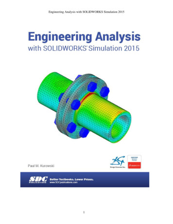
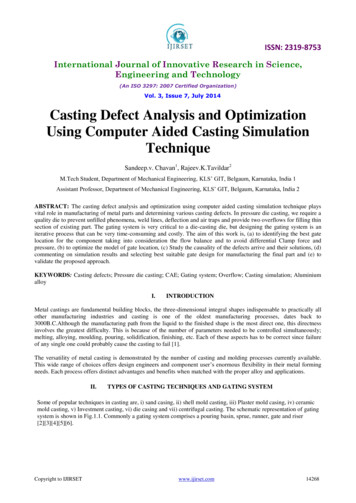
types of robots biped robots are the most challenging from stability view (Jin et al., 2010).Compare with biped robot, hexapod and quadruped robot have built-in static stability. Thecoordination and synchronization of the legs of the quadruped robot are simpler than the hexapodrobot. Therefore, in these three major types of legged robot, the morphology of the quadrupedrobot is the least complex, which results in a less complicated control system.1.3 Previous WorkThe previous student worked in the Design, innovation and simulation lab at the Ohio StateUniversity, Yupeng Cheng, designed and prototyped a transformable quadruped robotic leg(2018) which can successfully transform between leg and wheel. The transformable robot(wheel-legged robot), which combined the advantages of the high mobility and agility of thelegged robot and the high maneuverability and stability of the wheeled robot, which can besuitable in conditions where the robot need to navigate on a large amount of well-structuredground and a small number of obstacles. The robot can transform between two forms to achievemore efficient use of time and power on different terrains.The final designed robot has degree a of freedom on the roll, pitch, and yaw. There are threeactuators on each leg used for turning the forearm, the main arm and the shoulder which workslike the three major joints on the leg of typical four-legged animals, such as dogs (Figure 1).8
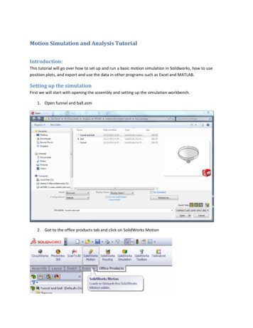
Figure 1: Comparison of the position of three actuators on the robot leg and the joints on the dogleg.In this design, the servo motor at the elbow helps to manage the transformation process.When the robot needs to move on the rough terrain, the wheel on the leg can be disabled and therobot can navigate using legs. When there is a large amount of flat surface, the leg can be foldedand reveal the wheel to move (Figure 2).Figure 2: Transformation process of transformable quadruped robot.9
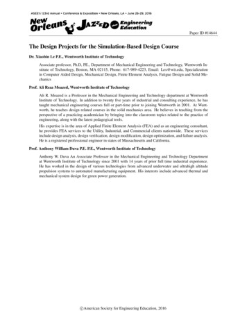
1.4 Objectives of this researchThere is one remained problem of the transformable robotics leg designed by previousstudents in the DISL lab. Assuming a situation of lifting the thigh to across some obstacles(Figure 3), the weight of the servo motor at the elbow that rotates the forearm can create a largeinertia to the motor at the shoulder, which did not conform to minimize mass and inertiaprinciple of design a leg (McKenzie, 2012). Also, the high inertia caused by the weight of themotor can lead to high cost of buying the motor and increase the potential risk of breaking themotors.Figure 3: Complete assembly and conceptual figure of the transformable robotics leg.The required input torque to lift the leg can be written as:𝜏𝑖𝑛 𝜏𝑜𝑢𝑡 �� Output torque, torque required to lift up the linkages𝑟 Length of the thigh10
𝑚 Mass of the motor at the elbowg gravitational constant, 9.8m/s2𝜃 angle between vertical line and the thighTherefore, the main purpose of this research is redesigning the leg of the quadruped robotusing a different mechanism to reduce the inertia caused by the weight of motor at the elbow tothe motor at the shoulder. More specific objectives are finding a mechanism that can be used toreduce the inertia caused by the weight of the motor, redesigning the quadruped robot leg usingthat mechanism, creating the Solidworks and Simscape Multibody models of the whole robot andsimulating the scenarios of the robot walking, trotting, bounding, and pacing.1.5 Overview of the thesisThis thesis focuses on discussing the design process of the platform, the mechanism usedto achieve the design requirement, how the design been analyzed and simulated, and the finalresults of the simulations. Chapter 2 discusses the platform design of the quadruped robot.Chapter 3 discusses the analysis methods of the design. Chapter 4 focuses on discussing thetrajectory planning for the quadruped robot. Chapter 5 discusses the Simscape Multibody of thedesign. Chapter 6 talks about the simulation scenarios and results of the design. Lastly, chapter 7concludes the research progress and future works. The standard 3 views of the Solidworks modelof the platform components, the Simscape multibody block diagrams, and the MATLAB codesare included in the appendix as references.11
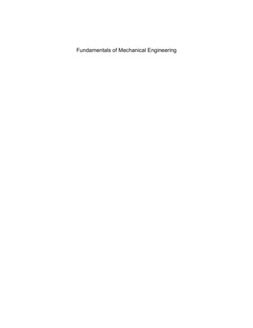
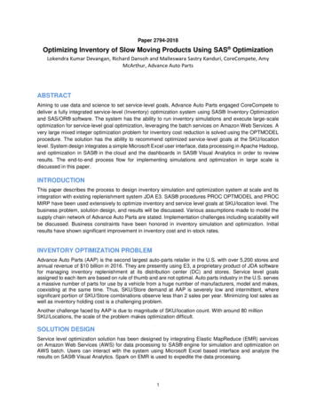
Chapter 2: Platform Design2.1 Design ConstraintsThe design constraints of the quadruped robot are as follows: The overall maximum dimension should be 400mm long, 300mm wide and 240mm high. The motors should be chosen from ROBOTIS DYNAMIXEL MX series. Considering the compatibility between the motors and the linkages on the leg, thebrackets sold by the ROBOTIS company should be used to directly connect the motorshafts. The designed robot should have 3 degrees of freedom for each leg and a total of 12degrees of freedom for 4 legs. The whole robot should have a degree of freedom on theroll, yaw and pitch axis. Conceptually, the upper limb should be able to swing about -60 degree to 60 degree tothe vertical line and the lower limb should be able to swing about -30 degree to 90degree relative to the horizontal line (Figure 4).Figure 4: Workspace constrain of the limb.12
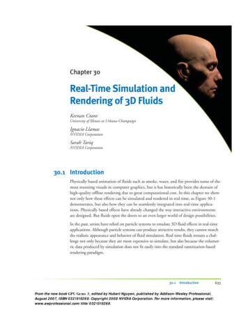
2.2 5-bar Linkage MechanismThe 5-bar linkage mechanism, the closed chain of 5 linkages, has two degrees of freedomwhich is the same as the 2 linkages open chain of the previous transformable leg. One motor candirectly drive the upper limb. Another motor can indirectly drive the lower (Figure 5). Also,designing the robotics leg using the 5-bar linkage mechanism can reduce the inertia caused bythe weight of the motor, since the two actuators can be put close together on the same groundaxis.Figure 5: Simplified five bar linkage robotic leg.2.3 Arrangement of the MotorsThe arrangement of the motors was determined using Solidworks and based on thedimension constraint of the robot. The model of the largest motor in the DROBOTISDYNAMIXEL MX series, the MX64R was downloaded from the DYNAMIXEL Company andused to determine the motor arrangement as well. Placing two motors along lateral axis was tried13
(Figure 6). However, because of the limitation of 300mm wide of the robot, there is not enoughspace for the third motor.Figure 6: Arrangement of the 8 leg motors along the lateral axis.After that, placing two motors along longitudinal axis was tried (Figure 7). There isenough space (199mm) between each limb to place the third motor to achieve the degree offreedom on the roll axis. Therefore, the arrangement of placing two motors along longitudinalaxis can be used to design the 5-bar linkage leg.14
Figure 7: Arrangement of the 8 leg motors along the longitudinal axis.Then, the same arrangement (Figure 8) as the previous design of placing the third motorhorizontally was checked using the SOLIDWORKS. However, there is limited space (46.50mm)for the linkages and thickness of the limb.Figure 8: Arrangement of the 8 leg motors along the longitudinal axis and the shouldermotors horizontally.15
The final arrangement of the motors is that place two motors along the longitudinal axisfor the 5-bar linkage mechanism and the third motor vertically aside of the other two motors.Also, a conceptual SOLIDWORKS model of the quadruped robot (Figure 9) was created tocheck the scale of the model. According to the conceptual model, there is enough space for thelinkages at the shoulder and the main body, so this arrangment can be used to do further design.Figure 9: Conceptual Solidworks model of the quadruped robot.2.4 Mechanical Design of the PlatformThe length of each bar was first determined using Solidworks sketch. The constraints oflinkage length were first the ground bar larger or equal to 40.2 mm, which is the width of twomotor, the length of bar 1 longer or equal to 24.08 mm, which is the minimum length of thebracket (Figure 10) modified from the commercial bracket FR05-H101 without collision with thebottom of the motor. In addition, the length of each should also satisfy the requirement that,16
without considering the collision, the upper limb should be able to swing about -60 degree to 60degree to the vertical line and the lower limb should be able to swing about -30 degree to 90degree relative to the horizontal line. To decide the specific length of the linkages, a closed framewith 5 binary links was draw using Solidworks sketches that the ground bar was 60.2 mm andfixed in order to leave enough space between the two motors for bar 1 to turn. Then multiple setsof the length of the other 4 links were tried to achieve the constraints of the workspace. Table xshows the specific length of each link for this design.Table 1: Link length of the robotic limbLink 1Link 2Link 3Link 4Link 532mm60mm40.11mm89.07mm60.2mmFigure 10: Solidworks model of the modified bracket.17
The mechanical model of the quadruped robot platform (Figure 11) has a dimension of400 mm long, 342 mm wide and 240 mm high, which exceed the 300 mm wide requirement inorder to leave enough space for the main body of the robot.Figure 11: Final Solidworks model of the quadruped robot platform.18
Chapter 3 Kinematics Analysis3.1 Forward kinematics of five-bar linkageForward kinematics is the process of using the forward kinematics equation to calculatethe end-effector of the robot given the joint parameters. In this case, the forward kinematicsequation can be used to find out the foot tip position of the limb, if the angles of the two motorsare known. Figure 12 below shows the model of one robotic leg and Figure 13 shows theschematic of the upside down 5-bar linkage robotic leg. The reason for creating the configurationof the leg upside down is that the coordination of the foot tip can always be positive, which waseasy to analyze. In the schematic figure of the 5-bar linkage limb, 𝑙1 , 𝑙2 , 𝑙3 , 𝑙4 , 𝑙5 and 𝑙 are thelength of the links and 𝜃1 , 𝜃2 , θ3 , 𝜃4 , 𝜃5 and 𝜃 are the angle of the links. The final forwardkinematic equations have two inputs, 𝜃4 and 𝜃1 , which are the angles of motor 1 and motor 2,and two outputs, the x and y coordinates of the foot tip.Figure 12: Solidworks model of one leg.19
Figure 13: Schematic figure of the 5-bar linkage limb.The position of foot tip can be found by adding up all orange vectors or all blue vector. Thefoot tip position equations of adding up the blue vectors from motor 2 to the foot tip goingthrough 𝑙1 , 𝑙2 , 𝑙3 and 𝑙, in x and y direction:𝑙1 𝑐𝑜𝑠𝜃1 𝑙2 𝑐𝑜𝑠𝜃2 𝑙3 𝑐𝑜𝑠𝜃3 𝑙 cos(𝜃 𝜃3 ) 𝑥(2)𝑙1 𝑠𝑖𝑛𝜃1 𝑙2 𝑠𝑖𝑛𝜃2 𝑙3 𝑠𝑖𝑛𝜃3 𝑙 sin(𝜃 𝜃3 ) 𝑦(3)The foot tip position equations of adding up the blue vectors from motor 2 to the foot tipgoing through 𝑙5 , 𝑙4 and 𝑙, in x and y direction:𝑙5 𝑙4 cos 𝜃4 𝑙 cos(𝜃 𝜃3 ) 𝑥(4)𝑙4 𝑠𝑖𝑛𝜃4 𝑙 sin(𝜃 𝜃3 ) 𝑦(5)20
Rearrange equations (2)-(5) and eliminate the unknown variables 𝜃2 and 𝜃3 to obtain theforward kinematic equations such that x and y coordinates of the foot tip are the outputs and theactuators’ angle, 𝜃4 and 𝜃1 , are the inputs:𝑥 𝑙5 𝑙4 cos 𝜃4 𝑙 cos(𝜃 2 arctan(𝑥1 ))(5)𝑦 𝑙4 𝑠𝑖𝑛𝜃4 𝑙 sin(𝜃 2 arctan(𝑥1 ))(6)Where,𝑥1 𝐷 𝐷2 (𝐴 𝐵 𝐶)(𝐴 𝐵 𝐶)𝐴 𝐵 𝐶𝐴 𝑙12 𝑙32 𝑙42 𝑙52 𝑙22𝐵 2𝑙5 𝑙4 𝑐𝑜𝑠𝜃4 2𝑙1 𝑙4 cos(𝜃4 𝜃1 ) 2𝑙5 𝑙1 𝑐𝑜𝑠𝜃1𝐶 2𝑙3 𝑙4 𝑐𝑜𝑠𝜃4 2𝑙5 𝑙3 2𝑙3 𝑙1 𝑐𝑜𝑠𝜃1𝐷 2𝑙3 𝑙4 𝑠𝑖𝑛𝜃4 2𝑙3 𝑙1 𝑠𝑖𝑛𝜃1𝑙1 length of link 1, 32.14 𝑚𝑚.𝑙2 length of link 2, 60 𝑚𝑚.𝑙3 length of link 3, 40.11 𝑚𝑚.𝑙4 length of link 4, 89.2 𝑚𝑚.𝑙5 length of link 5, 60.2 𝑚𝑚.𝑙 length of extended link 1, 106.78 𝑚𝑚.𝜃 Angle between link 3 and extended link l, 28 .3.2 Inverse kinematics equations of 5-bar linkageInverse kinematics is the process using the inverse kinematics to calculate the jointparameters given the end-effector of the robot. Rearrange equations (2)-(5) and eliminate the21
unknown variables 𝜃2 and 𝜃3 to obtain the inverse kinematic equations such that the actuators’angle, 𝜃4 and 𝜃1 , are the outputs and the x and y coordinates of the foot tip are the inputs:𝑦 𝑙 sin(𝜃 2 arctan(𝑎) 𝜃)𝜃4 arctan(𝑥 𝑙 cos(𝜃 2 arctan(𝑎) 𝜃) 𝑙 )5𝜃1 2 arctan(𝑏)(7)(8)Where,𝐾 𝐾 2 (𝑀2 𝑁 2 )𝑎 𝑀 𝑁𝑀 𝑦 2 (𝑥 𝑙5 )2 𝑙 2 𝑙42𝐾 2 𝑦 𝑙𝑁 2 (𝑥 𝑙5 ) 𝑙𝑏 𝑃 𝑃2 (𝑂2 𝑄 2 )𝑂 𝑄𝑂 (𝑥 𝑙3 𝑐𝑜𝑠𝜃3 𝑙 cos(𝜃 𝜃3 )) 2 (𝑦 𝑙3 𝑠𝑖𝑛𝜃3 𝑙 sin(𝜃 𝜃3 ))2 𝑙12 𝑙22𝑃 2 𝑙1 (𝑦 𝑙3 𝑠𝑖𝑛𝜃3 𝑙 sin(𝜃 𝜃3 ))𝑄 2 𝑙1 (𝑥 𝑙3 𝑐𝑜𝑠𝜃3 𝑙 cos(𝜃 𝜃3 ))3.3. Forward velocity kinematic of 5-bar linkageForward velocity kinematics equations can be used to calculate the velocity of the foot tip inx and y direction given the angular velocities of the two motors and angles of all links. To derivethe forward velocity kinematic equations of the robotic leg first is to differentiate equation (2)(5). The differentiated velocity equations: 𝑙1 𝑠𝑖𝑛𝜃1 𝜃1̇ 𝑙2 𝑠𝑖𝑛𝜃2 𝜃2̇ (𝑙3 𝑠𝑖𝑛𝜃3 𝑙 sin(𝜃 𝜃3 )) 𝜃3̇ 𝑥̇(9)22
𝑙1 𝑐𝑜𝑠𝜃1 𝜃1̇ 𝑙2 𝑐𝑜𝑠𝜃2 𝜃2̇ (𝑙3 𝑐𝑜𝑠𝜃3 𝑙 cos(𝜃 𝜃3 )) 𝜃3̇ 𝑦̇(10) 𝑙4 𝑠𝑖𝑛𝜃4 𝜃4̇ 𝑙 sin(𝜃 𝜃3 ) 𝜃3̇ 𝑥 ̇(11)𝑙4 𝑐𝑜𝑠𝜃4 𝜃4̇ 𝑙 cos(𝜃 𝜃3 ) 𝜃3̇ 𝑦̇(12)Rearrange equation (9)-(12) and eliminate the unknown variables 𝜃̇2 and 𝜃̇3 to obtain theforward velocity kinematic equations such that the foot tip velocity, 𝑥̇ and 𝑦̇ , are the outputs andthe actuators’ angular velocity, 𝜃̇4 and 𝜃̇1 , are the inputs:𝑥̇ ( tan(𝜃 𝜃3 ) 𝛼)𝜃1̇ ( 𝑙4 𝑠𝑖𝑛𝜃4 tan(𝜃 𝜃3 ) 𝑙4 𝑐𝑜𝑠𝜃4 tan(𝜃 𝜃3 )𝛽)𝜃4̇𝑦̇ 𝛼𝜃1̇ 𝛽𝜃4̇(13)(14)Where,𝛼 (( 𝑙1 𝑠𝑖𝑛𝜃1 𝑡𝑎𝑛𝜃2 𝑙1 𝑐𝑜𝑠𝜃1 ))𝑙3 𝑐𝑜𝑠𝜃3𝑙3 𝑠𝑖𝑛𝜃3(𝑡𝑎𝑛𝜃2 ( ) )𝑙 cos(𝜃 𝜃3 )𝑙 cos(𝜃 𝜃3 )𝑙 𝑐𝑜𝑠𝜃3( 𝑡𝑎𝑛𝜃2 ( 3 1) 𝑙4 𝑐𝑜𝑠𝜃4 𝑙3 𝑠𝑖𝑛𝜃3 𝑙4 𝑐𝑜𝑠𝜃4 𝑙4 𝑠𝑖𝑛𝜃4 )𝑙 cos(𝜃 𝜃3 )𝛽 ()𝑙3 𝑐𝑜𝑠𝜃3𝑙3 𝑠𝑖𝑛𝜃3(𝑡𝑎𝑛𝜃2 ( ) )𝑙 cos(𝜃 𝜃3 ) 𝑙cos(𝜃 𝜃3 )3.4. Inverse velocity kinematic of 5-bar linkageInverse velocity kinematic equations can be used to calculate angular velocities of the twomotors given the velocity of the foot tip in x and y direction and angles of all links. Rearrangeequation (9)-(12) and eliminate the unknown variables 𝜃̇2 and 𝜃̇3 to obtain the inverse velocitykinematic equations such that the actuators’ angular velocity, 𝜃̇4 and 𝜃̇1 , are the outputs and thefoot tip velocity, 𝑥̇ and 𝑦̇ , are the inputs:23
( 𝑙4 𝑠𝑖𝑛𝜃4 tan(𝜃 𝜃3 ) 𝑙4 𝑐𝑜𝑠𝜃4 tan(𝜃 𝜃3 )𝛽)𝑦̇𝛽𝜃1̇ ( tan(𝜃 𝜃3 ) 𝛼) (𝑙4 𝑠𝑖𝑛𝜃4 tan(𝜃 𝜃3 ) 𝑙4 𝑐𝑜𝑠𝜃4 tan(𝜃 𝜃3 )𝛽)𝛼/β𝑥̇ (15)𝜃4̇ (𝑦̇ 𝛼 𝜃1̇ )/β(16)Where, 𝛼 and 𝛽 are the same equations as the ones under section 3.3.3.5. The torque equations of the 5-bar linkageIn order to further analyze the actuator torque required to achieve the designed motion,torque equations of the two motors were derived. The derivation was based on the principle ofvirtue work that assumes there is no power loss on the limb. The power input of the two motorsshould be equal to the power output at the foot tip. The power conservation equations of the limbin matrix form:[𝐹𝑥𝑥̇𝐹𝑦 ] { } [𝜏1𝑦̇̇𝜏4 ] {𝜃1 }𝜃4̇(17)Where,𝐹𝑥 The ground force act on the foot tip in x direction, N.𝐹𝑦 The ground force act on the foot tip in y direction, N.𝑥̇ The linear velocity of the foot tip in x direction, m/s.𝑦̇ The linear velocity of the foot tip in y direction, m/s.𝜏4 Actuation torque of motor 1, Nm.24
𝜏1 Actuation torque of motor 2, Nm.Plugging the inverse velocity kinematic equations, the equation 13 and 14, into the powerconservation equations to cancel out the angular velocity of the two motors, 𝜃̇1 and 𝜃̇41 , theactuation torque equation was obtained:𝜏1 𝐹𝑥 ( tan(𝜃 𝜃3 ) 𝛼) 𝐹𝑦 𝛼𝜏4 𝐹𝑥 ( 𝑙4 𝑠𝑖𝑛𝜃4 tan(𝜃 𝜃3 ) 𝑙4 𝑐𝑜𝑠𝜃4 tan(𝜃 𝜃3 ) 𝛽) 𝐹𝑦 𝛽(18)(19)Where, 𝛼 and 𝛽 are the same equations as the ones under section 3.3.3.6. Workspace analysis of the robotic legTo avoid the collision between the components might either snap the linkages or damagethe motors, the workspace of the robotic leg needs to be found, before planning the trajectory. Inthis research, the interference detection function in the Solidworks was used to find the range ofmotor angles without collision. This function can be found under “Evaluate” in the Solidworkassembly interface. It can help to detect if there is an overlap between the chosen componentsand the volume of the interference.To evaluate the workspace of the designed quadruped robotic leg, first, the minimumangular position of motor 1 without collision was found. Then the corresponding minimum andmaximum position of motor 2 were measured using the interference detection function. Afterthat, the previous step with 2-degree increment of the angular position of motor 1 were repeateduntil motor 1 reached its maximum angle. The angular workspace results of the two motors wereshown in Figure 14, where the x-axis is the angle of motor 2 and y-axis is the angle of motor 1.25
Figure 14: Angular workspace results of the two motors.The workspace of the limb tip was calculated by plugging the angle workspace of the twomotors into the forward kinematic equation. The shaded area in Figure 15 below showsworkspace of the limb tip. The position of two motors are also displayed in the figure, where thecenter of motor 2 was set as the origin.Figure 15: Workspace of the foot tip of the robotic leg.26
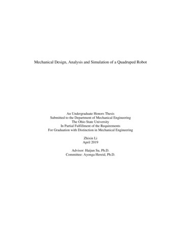
Chapter 4. Trajectory Planning4.1. Trajectory Planning of One LegThe trajectory of each foot tip of the robot move on the flat surface was designed to be a“D” shape, where the straight line represents the stance phase and the curve line represents theflight phase. The foot tip trajectory does not have to be a perfectly smooth “D” shape curve aslong as inside the workspace of the limb. However, considering the work required of one gaitcycle, the length of the curve should be as short as possible. Also, considering the performanceof the motor the sharp turns should be avoided.The curve below shows the upside-down “D” shape the trajectory of the robot walking,trotting, pacing, and bounding. L1 is the length of the straight portion on the ground. L2 is themaximum length of the trajectory. H1 is the maximum height of the curve, also being consideredas the height that the foot tip will lift. H2 is the height from the ground to one point on the sidecurve. X and y are the distances in the horizontal and vertical direction from the center point ofthe straight line to the position of the motor 2. The parameters of the trajectory can be changed inthe MATLAB to easily modify the size of the gait.Figure 16: “D” shape trajectory of the robot.27
For a quadruped robot, the stance phase takes three fourths of one period and the flighttakes one-fourth of one period (Zhou et al., 2016). To achieve this, the straight portion of thetrajectory were divided into 36 equally spaced pieces and the curve was divided into 12 pieces,where the time duration of each piece is same so that the total time spent on the straight line willbe three times as the time spends on the curve portion. Figure 17 below shows the distribution ofthe critical points and Table 2 shows the coordinates of the critical points used to fit thetrajectory.Figure 17: Critical points distribution of the trajectory.Table 2: Coordination of the trajectory critical points.𝑙1, 𝑦)214𝑙1P5 (𝑥 , 𝑦)3610𝑙1P9 (𝑥 , 𝑦)366𝑙1P13 (𝑥 , 𝑦)362𝑙1P17 (𝑥 , 𝑦)362𝑙1P21 (𝑥 , 𝑦)366𝑙1P25 (𝑥 , 𝑦)3610𝑙1P29 (𝑥 , 𝑦)3614𝑙1P33 (𝑥 , 𝑦)36𝑙1P37 (𝑥 , 𝑦)2𝑙2P41 (𝑥 , 𝑦 ℎ2 )2𝑙1P45 (𝑥 , 𝑦 ℎ2 )2P1 (𝑥 17𝑙1, 𝑦)3613𝑙1P6 (𝑥 , 𝑦)369𝑙1P10 (𝑥 , 𝑦)365𝑙1P14 (𝑥 , 𝑦)36𝑙1P18 (𝑥 , 𝑦)363𝑙1P22 (𝑥 , 𝑦)367𝑙1P26 (𝑥 , 𝑦)3611𝑙1P30 (𝑥 , 𝑦)3615𝑙1P34 (𝑥 , 𝑦)36𝑙1 𝑙2 𝑙1ℎ2P38 (𝑥 ,𝑦 )234𝑙15ℎ1P42 (𝑥 , 𝑦 )46𝑙1 𝑙2 𝑙13ℎ2P46 (𝑥 ,𝑦 )234P2 (𝑥 16𝑙1, 𝑦)3612𝑙1P7 (𝑥 , 𝑦)368𝑙1P11 (𝑥 , 𝑦)364𝑙1P15 (𝑥 , 𝑦)36P3 (𝑥 P19 (𝑥, 𝑦)4𝑙1, 𝑦)368𝑙1P27 (𝑥 , 𝑦)3612𝑙1P31 (𝑥 , 𝑦)3616𝑙1P35 (𝑥 , 𝑦)36𝑙2ℎ2P39 (𝑥 , 𝑦 )22P23 (𝑥 P43 (𝑥, 𝑦 ℎ1 )P47 (𝑥 𝑙2ℎ2,𝑦 )2215𝑙1, 𝑦)3611𝑙1P8 (𝑥 , 𝑦)367𝑙1P12 (𝑥 , 𝑦)363𝑙1P16 (𝑥 , 𝑦)36𝑙1P20 (𝑥 , 𝑦)365𝑙1P24 (𝑥 , 𝑦)369𝑙1P28 (𝑥 , 𝑦)3613𝑙1P32 (𝑥 , 𝑦)3617𝑙1P36 (𝑥 , 𝑦)36𝑙1 𝑙2 𝑙13ℎ2P40 (𝑥 ,𝑦 )234𝑙15ℎ1P44 (𝑥 , 𝑦 )46𝑙1 𝑙2 𝑙1ℎ2P48 (𝑥 ,𝑦 )234P4 (𝑥 28
Fifth order polynomial was used to fit the trajectory, so the velocity and acceleration ofthe curve are continuous (Biagiotti and Melchiorri, 2010). Also, the values of the velocity andacceleration at the critical point can be manually assigned. In order to obtain a smooth curve, thevertical velocity at the critical number 43 and 37 was assigned as zero, the overall velocity atcritical number 40 and 41 was same and the overall velocity at critical number 46 and 47 wassame as well. Figure 18 shows one sample fitted trajectory on the workspace graph. Thetrajectory is very smooth and passes through all critical points assigned. Also, it falls inside therange of the foot tip workspace of the design quadruped robot, which mean
Mechanical Design, Analysis and Simulation of a Quadruped Robot An Undergraduate Honors Thesis Submitted to the Department of Mechanical Engineering The Ohio State University In Partial Fulfillment of the Requirements For Graduation with Distinction in Mechanical E