Transcription
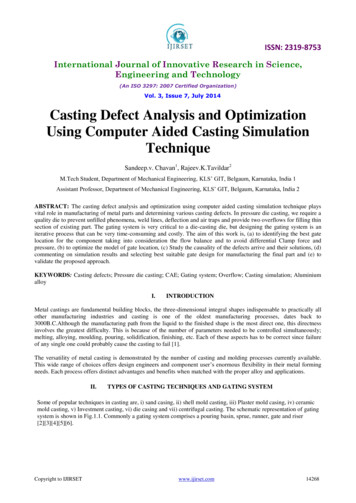
ISSN: 2319-8753International Journal of Innovative Research in Science,Engineering and Technology(An ISO 3297: 2007 Certified Organization)Vol. 3, Issue 7, July 2014Casting Defect Analysis and OptimizationUsing Computer Aided Casting SimulationTechniqueSandeep.v. Chavan1, Rajeev.K.Tavildar2M.Tech Student, Department of Mechanical Engineering, KLS’ GIT, Belgaum, Karnataka, India 1Assistant Professor, Department of Mechanical Engineering, KLS’ GIT, Belgaum, Karnataka, India 2ABSTRACT: The casting defect analysis and optimization using computer aided casting simulation technique playsvital role in manufacturing of metal parts and determining various casting defects. In pressure die casting, we require aquality die to prevent unfilled phenomena, weld lines, deflection and air traps and provide two overflows for filling thinsection of existing part. The gating system is very critical to a die-casting die, but designing the gating system is aniterative process that can be very time-consuming and costly. The aim of this work is, (a) to identifying the best gatelocation for the component taking into consideration the flow balance and to avoid differential Clamp force andpressure, (b) to optimize the model of gate location, (c) Study the causality of the defects arrive and their solutions, (d)commenting on simulation results and selecting best suitable gate design for manufacturing the final part and (e) tovalidate the proposed approach.KEYWORDS: Casting defects; Pressure die casting; CAE; Gating system; Overflow; Casting simulation; AluminiumalloyI.INTRODUCTIONMetal castings are fundamental building blocks, the three-dimensional integral shapes indispensable to practically allother manufacturing industries and casting is one of the oldest manufacturing processes, dates back to3000B.C.Although the manufacturing path from the liquid to the finished shape is the most direct one, this directnessinvolves the greatest difficulty. This is because of the number of parameters needed to be controlled simultaneously;melting, alloying, moulding, pouring, solidification, finishing, etc. Each of these aspects has to be correct since failureof any single one could probably cause the casting to fail [1].The versatility of metal casting is demonstrated by the number of casting and molding processes currently available.This wide range of choices offers design engineers and component user’s enormous flexibility in their metal formingneeds. Each process offers distinct advantages and benefits when matched with the proper alloy and applications.II.TYPES OF CASTING TECHNIQUES AND GATING SYSTEMSome of popular techniques in casting are, i) sand casing, ii) shell mold casting, iii) Plaster mold casing, iv) ceramicmold casting, v) Investment casting, vi) die casing and vii) centrifugal casting. The schematic representation of gatingsystem is shown in Fig.1.1. Commonly a gating system comprises a pouring basin, sprue, runner, gate and riser[2][3][4][5][6].Copyright to IJIRSETwww.ijirset.com14268
ISSN: 2319-8753International Journal of Innovative Research in Science,Engineering and Technology(An ISO 3297: 2007 Certified Organization)Vol. 3, Issue 7, July 2014Figure.1.Gating system2.1 Casting defects: Foundry industries in developing countries suffer from poor quality and productivity due toinvolvement of number of process parameters in casting process. Even in a completely controlled process, defects incasting are observed and hence casting process is also known as process of uncertainty which challenges explanationabout the cause of casting defects [7]. Defects found in castings may be divided in to three classesa. Defects which can be noticed on visual examination or measurement of the casting.b. Defects which exists under surface and are revealed by machining, sectioning or radiography.c. Material defects discovered by mechanical testing (tensile, bending, impact, etc) of the casting.Some defects are common to any and all casting processes are misrun, cold shut, cold shot, hot tear, porosity etcIII.METHODOLOGY3.1 Guidelines for processingFill time: The casting should have enough space on the parting line for the gate and vents. The gate length is the gatearea divided by the gate thickness. The gate area depends on selected die cavity fill time and gate velocity. Die cavityfill time is selected on the grounds of, i) Thinnest casting wall thickness, ii) Thermal properties of casting alloy anddie material,iii) Combined volume of the casting and overflows and iv) Percentage solidified metal allowed during filling.{}(1)Gate area: Total gate area is calculated with the cavity fill time, gate velocity and total casting overflows volumeaccording to the following equation.(2)Gate velocity: Possible gate thickness range depends on the selected gate velocity (or vice versa) according to thefollowing equation.(3)3.2 Casting simulation for casting defect analysisSimulation is the process of imitating a real phenomenon using a set of mathematical equations implemented in acomputer program. In casting simulation the mould filling and solidification analysis is done to identify the hot spotsand hence defects like shrinkage porosities, hot tears, cracks, etc. The simulation programs are based on finite elementanalysis of 3D models of castings and involve sophisticated functions for user interface, computation and display. Thecasting model (with feeders and gates) has to be created using a solid modeling system and imported into thesimulation program. The casting simulation and optimization methodology is detailed in following table.1Copyright to IJIRSETwww.ijirset.com14269
ISSN: 2319-8753International Journal of Innovative Research in Science,Engineering and Technology(An ISO 3297: 2007 Certified Organization)Vol. 3, Issue 7, July 2014TABLE 1: Casing simulation and optimisation methodologySTEP 1: Data GatheringPart model, Material, Process parameters, Methods design, Existing defectsParting line, Cores, Feeders, Gating system, mold cavity layoutSTEP 2: Methods DesignSTEP 3: SimulationModel import, Mesh generation, Material and process, VisualizationModify design, Simulation, Check quality,STEP 4: OptimizationSTEP 5: Project ClosureMethods report, Analysis report, Compare results, Archive projectIV.FINITE ELEMENT ANALYSIS4.1 Data collection:In this stage for selected casting the data regarding the, process parameters, materials, methods design is collectedand analysed. The following table 2 details the process parameters and material used for the processing.TABLE: 2 Process parametersMaterialDie temperatureMelting temperatureDensityFill timeAluminium alloy -1100288oC643oC2712 Kg/m30.075sec4.1 CAD model design:Input to the simulation program is the 3D solid CAD model of the casting in STEP format, so 3D solid CAD model oftwo wheeler mirror stay was created as shown in Figure 2.Figure.2 solid model of mirror stay part4.2 simulation and optimisation:The following figure.3 shows the mesh model of existing part and simulation result for finding best gate location. The3D CAD model is meshed using hyper mesh tool which is a preprocessor. Fusion mesh (tetra mesh) pattern is used.Copyright to IJIRSETwww.ijirset.com14270
ISSN: 2319-8753International Journal of Innovative Research in Science,Engineering and Technology(An ISO 3297: 2007 Certified Organization)Vol. 3, Issue 7, July 2014Figure.3 mesh model and best gate locationTo find the best gate location for gate design, we need to consider the following factors i) No flow hesitation,ii)Flow balance, iii) Less pressure (equal pressure distribution) and iv) Clamp force. Therefore the followingfigure.4,5,6 and 7 shows the different gate location’s simulation results for existing part respectively.(a)(b)(d)(c)Fig.4. No flow hesitation (a) Gate location 1 (b) Gate location 2 (c) Gate location 3 (d) Gate location 4(a)(b)(c)(d)Figure.5 Flow balance (a) Gate location 1 (b) Gate location 2 (c) Gate location 3 (d) Gate location 4Copyright to IJIRSETwww.ijirset.com14271
ISSN: 2319-8753International Journal of Innovative Research in Science,Engineering and Technology(An ISO 3297: 2007 Certified Organization)Vol. 3, Issue 7, July 2014(a)(b)(d)(c)Figure.6 Pressure distribution (a) Gate location 1 (b) Gate location 2 (c) Gate location 3 (d) Gate location 4(a)(b)(d)(c)Figure.7 clamp force (a) Gate location 1 (b) Gate location 2 (c) Gate location 3 (d) Gate location 4Comparing all these four factors like Flow hesitation, Flow balance, Pressure and clamp force respectively, gate 1,2, and 3 have no flow hesitation, flow is balanced and also pressure and clamp force are almost same. But in gatelocation there is hesitation in flow and also the region of the gate location not good for gate design. Hence gate 2and 4 are the best gate location for gate design and further analysis.4.4 Gate design:The following figure.8 shows the gate design 1 and 2 respectively for existing part. In this section we arecomparing the results of both gating systems and going to conclude for best one for final processing.(a)(b)Figure.8 Gate design (a) Gate design 1 (b) Gate design 2The following figure.9 shows the simulation results of both gate design 1 & 2 respectively for different parametersCopyright to IJIRSETwww.ijirset.com14272
ISSN: 2319-8753International Journal of Innovative Research in Science,Engineering and Technology(An ISO 3297: 2007 Certified Organization)Vol. 3, Issue 7, July 2014a)(b)(d)(c)Figure.9 no flow hesitation and flow balance of gate design 1 & 2 (a & c) No flow hesitation (b & d) Flow balanceThe figure.10 shows the defects observed after simulation for gate design 1 & 2 respectively(a)(b)(c)Fig.10 simulation results for Gate design-1 (a) weld line (b) Air traps (c) Deflection in XYZ direction(a)(b)(c)Fig.11 simulation results for Gate design-2 (a) weld line (b) Air traps (c) Deflection in XYZ directionCopyright to IJIRSETwww.ijirset.com14273
ISSN: 2319-8753International Journal of Innovative Research in Science,Engineering and Technology(An ISO 3297: 2007 Certified Organization)Vol. 3, Issue 7, July 2014Comparing the simulation results like filling, fill time, pressure deflection and clamp force of gate design 1 & 2 and isas detailed in the following table.3 below. Here gate design 2 is comparatively better than 1 for all aspects. Hence thisgate design recommended to customer.TABLE.3 Result comparison of gate design 1 & 2Filling (contour)Fill time (sec)Pressure (MPa)Deflection (mm)Clamp force(tonne)Gate design INormal flow0.0836 (100%)16.225.00331.65V.Gate design IINormal flow0.0822 (100%)13.123.49425.85CONCLUSIONBased on results, the following results were drawn:1. A new method of casting defect analysis is proposed and studied that is Computer aided casting simulationtechnique for analysis of rejection of casting due to defects related to die casting.2. A proper runner and gating system is very important to secure good quality die casting through providing ahomogenous mould filling pattern.3. More overflow entrances should be added at the end of the cavity to eliminate the premature freezing of themolten metal. In addition, for thin die casting, side-wall overflow of the cavity is needed to prevent turbulentflow by including the high velocity molten metal to the overflow4. For analysis of defects like weld lines, air traps and shrinkage, computer aided casting simulation technique isthe most efficient and accurate method. The quality and yield of the casting can be efficiently improved bycomputer assisted casting simulation technique in shortest possible time and without carrying out the actualtrials on foundry shop floor.5.Finally we suggest to customer that the gate location, feed system dimensionREFERENCES[1]John Campbell “The new metallurgy of cast metals CASTINGS”, second edition, Butterworth-Heinemann publications, 2003.[2] Serope Kalpakjian, Steven R. Schmid “Manufacturing Engineering and Technology” sixth edition, Pearson publication, Jan 2009, (259-260).[3] Rajender Singh “Introduction to basic Manufacturing processes and workshop technology”. New age international (P) Ltd., Publishers, firstedition 2006,(241-256).[4] F. Bonollo, J. Urban, B. Bonatto, M. Botter “Gravity and low pressure die casting of aluminium alloys: a technical and economical benchmark”La Metallurgia Italiana journal, june 2006 (23-33).[5] Mikell P. Groover “Fundamentals of Modern Manufacturing: Materials, Processes, and Systems” 4th edition, John Wiley & sons, inc. 2010.[6] Tuula Hook “CAE DS-High Pressure Die Casting Design”, Tampere University of Technology, Finland.[7] Uday A. Dabade and Rahul C. Bhedasgaonkar “Casting Defect Analysis using Design of Experiments (DoE) and Computer Aided CastingSimulation Technique” Forty Sixth CIRP Conference on Manufacturing Systems 2013 Procedia CIRP 7 ( 2013 ) 616 – 621.[8] Achamyeleh A. Kassie, Samuel B. Assfaw “Minimization of Casting Defects” IOSR Journal of Engineering Vol. 3, Issue 5 (May. 2013) PP 3138.[9] Chul Kyu Jin, Chan Hyun Jang and Chung Gil Kang “Die design optimization of die casting for fabrication of fuel cell aluminum bipolar platewith micro-channel through casting simulation and experimental investigation” Journal of Mechanical Science and Technology 27 (10) (2013) 29973003.[10] B.H. Hu, K.K. Tong, X.P. Niu, I. Pinwill “Design and optimisation of runner and gating systems for the die casting of thin-walled magnesiumtelecommunication parts through numerical simulation” Journal of Materials Processing Technology, May 2000, (128-133).Copyright to IJIRSETwww.ijirset.com14274
3.2 Casting simulation for casting defect analysis Simulation is the process of imitating a real phenomenon using a set of mathematical equations implemented in a computer program. In casting simulation the mould filling and solidif ication analysis is done to identify the hot spots and hence defects like shrinkage porosities, hot tears, cracks, etc. The s imulation programs are based on .Cited by: 1Publish Year: 2014Author: K. Tavildar, M. Tech Student