Transcription
Dell Networking and Cisco SpanningTree InteroperabilitySpanning-Tree interoperability between Dell FTOS and Cisco Nexus OSusing VLT and vPCA Dell Technical White PaperMario ChowDell Networking - Technical Marketing
Dell Networking: Spanning-tree with VLT and vPCThis document is for informational purposes only and may contain typographical errors andtechnical inaccuracies. The content is provided as is, without express or implied warranties of anykind. 2013 Dell Inc. All Rights Reserved. Dell, the Dell logo, and other Dell names and marks aretrademarks of Dell Inc. in the US and worldwide. All other trademarks mentioned herein are theproperty of their respective owners.July 2013 Rev 1.0ii
Dell Networking: Spanning-tree with VLT and vPCTable of ContentsExecutive Summary . 5Introduction . 5Test Methodology . 9Hardware . 10Software . 10Tests – VLT (Aggregation) and vPC (Core) . 10Test #1 – RSTP (Dell S4810s) and RPVST (Cisco 5548UP) . 10Test Case #2 – RSTP (Dell S4810s) and MST (Cisco 5548UP) . 14Tests – no VLT (Aggregation) no vPC (Core) . 16Test Case # 1 - RSTP (Dell S4810s) and RPVST (Cisco 5548UP) . 17Test Case # 2 - PVST (Dell S4810s) and RPVST (Cisco 5548UP) . 20Test Case # 3 - RSTP (Dell S4810s) and MST (Cisco 5548UP) . 22Common/single spanning-tree instance . 23Multiple spanning-tree instance . 25Test Case # 4 - MSTP (Dell S4810s) and MST (Cisco 5548UP) . 26Summary . 27Miscellaneous – Switch Configurations . 29Cisco 5548UP - RPVST with vPC . 29Dell S4810 – RSTP with VLT. 30FiguresFigure 1: Dell VLT Topology . 6Figure 2: Cisco vPC Typical Deployment . 6Figure 3 : Physical and logical reference network Test-Bed . 8Figure 4 : Test setup without vPC and VLT . 9Figure 5 : Physical and Logical Network Topology - vlan 20 . 11Figure 6 : VLT LAG Peer Status . 12Figure 7: Cisco RPVST link status . 13Figure 8: S4810s RSTP link status . 13Figure 9: Stream Statistics for Vlan 10 . 14Figure 10 : Physical and Logical Network Topology . 15Figure 11: Traffic port statistics during link fail-over . 16Figure 12: Physical Network Topology RSTP (Dell) and RPVST (Cisco) . 17Figure 13 : Vlan 20 spanning tree instance N5K 1. 17Figure 14 : Vlan 10 spanning tree instance N5K 2. 18iii
Dell Networking: Spanning-tree with VLT and vPCFigure 15 : RSTP BPDU for vlan 10. 19Figure 16: Cisco RPVST Spanning-Tree Debug . 19Figure 17 : Screen shot during fail-over . 20Figure 18: Physical and logical network topology - RPVST & PVST . 20Figure 19: Vlan 10 S4810 link status per spanning-tree . 21Figure 20 : Vlan 20 traffic spanning-tree. 21Figure 21 : Physical and logical network topology . 22Figure 22: Cisco link status per MST . 23Figure 23 : Dell S4810 RSTP link status . 23Figure 24 : Port transition S4810 1 RSTP . 24Figure 25 : Cisco MST port state . 25Figure 26 : Cisco MST port state . 25Figure 27 : Physical and logical network topology . 26TableTable 1: Spanning-Tree Traffic Convergence Results . 27iv
Dell Networking: Spanning-tree with VLT and vPCExecutive SummarySpanning-tree continues to play an important role in today’s networks. Despite the inherent issues ofinefficient use of bandwidth, scalability limitations, and overall management complexity, it is one of themost basic implementations deployed on existing legacy networks.Because of this large install base, any major networking vendor’s end-to-end solution must be able toseamlessly integrate its products and solutions into an existing deployment running any basic orenhanced spanning-tree modes such as RSTP (Rapid Spanning-Tree also known as 802.1w) or MST(Multiple Spanning-Tree also known as 802.1s).The Dell Networking product portfolio brings this value to the customer by having a complete set ofspanning-tree features that fully interoperate and integrate into an existing deployment. Thisinteroperability document runs through several of the most common spanning-tree deployments andshows how Dell’s implementations provide great performance – less than 0.001% packet loss - andhigh-availability – less than 0.001 seconds of switchover - during a link failure in the network.IntroductionThe creation of the following interoperability document is a result engagements taking place betweenCisco switches and Dell switches running similar as well as different spanning-tree modes in theenterprise environment.This document characterizes and provides some insight into the network traffic behavior whendifferent flavors of spanning tree and device redundancy configurations are deployed between a Ciscoenvironment and a Dell switching environment.The intended audience of this document is the network architect, system engineer, or networkadministrator. The results of the tests that will be performed could be used as a reference point fornew designs or integration purposes.There are two major technologies that will be covered in this interoperability exercise:1.Device Redundancya.Dell FTOS VLT (Virtual Link Trunk)b. Cisco vPC (Virtual Port-Channel)2. Spanning-Tree ProtocolDell FTOS VLT - Virtual Link Trunk (VLT) allows physical links between two chassis to appear as asingle virtual link to the network core or other switches such as Edge, Access or ToR. VLT reduces therole of Spanning Tree protocols by allowing LAG terminations on two separate distribution or coreswitches where these switches can be from any other networking vendor supporting standard LAGimplementation, and by supporting a loop free topology. (A Spanning Tree protocol is still needed toprevent the initial loop that may occur prior to VLT being established. After VLT is established, RSTPmay be used to prevent loops from forming with new links that are incorrectly connected and outsidethe VLT domain.) VLT provides Layer 2 multi-pathing, creating redundancy through increasedbandwidth, enabling multiple parallel paths between nodes and load-balancing traffic wherealternative paths exist.5
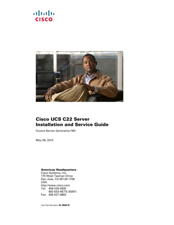
Dell Networking: Spanning-tree with VLT and vPCFigure 1: Dell VLT Topology, shows the typical physical network layout with Dell’s VLT.Figure 1: Dell VLT TopologyCisco vPC - A Virtual Port-Channel (vPC) allows links that are physically connected to two differentCisco Nexus 5000 Series devices to appear as a single Port-Channel to a third device. The thirddevice can be a Cisco Nexus 2000 Series Fabric Extender or a switch, server, or any other networkingdevice. A vPC can provide Layer 2 multi-pathing, which allows you to create redundancy by increasingbandwidth, enabling multiple parallel paths between nodes and load-balancing traffic wherealternative paths exist.The vPC domain includes both vPC peer devices, the vPC peer keepalive link, the vPC peer link, and allthe Port-Channels in the vPC domain connected to the downstream device. You can have only onevPC domain ID on each device.Figure 2: Cisco vPC Typical Deployment shows the typical Cisco vPC deployment running the NexusOperating System. Notice how half of the links from the member switch connect to each vPC memberswitch.Figure 2: Cisco vPC Typical Deployment6
Dell Networking: Spanning-tree with VLT and vPCSpanning-Tree Protocol - The Spanning -Tree Protocol (STP) is a network protocol that ensures aloop-free topology for any bridged Ethernet local area network. The basic function of STP is toprevent bridge loops and the broadcast storms that result from these loops. Spanning-tree also allowsa network design to include spare (redundant) links to provide automatic backup paths if an active linkfails without the danger of creating any bridge loops, or the need for manual enabling/disabling ofthese backup links.Several enhancements or extensions have been made to the original spanning-tree (IEEE 802.1D)implementation. These are: RSTP (802.1w) – In 2001, the IEEE standards body introduced Rapid Spanning Tree as 802.1w.This enhancement provides significant faster spanning tree convergence after a networktopology change has taken place.While Spanning Tree can take between 30-50 seconds to respond to a topology change, RSTPis typically able to respond to changes within 6 seconds or milliseconds to a physical linkfailure. RSTP is backwards compatible with legacy spanning tree. MSTP (802.1s) - MSTP is an extension to RSTP which adds efficiency to the legacy spanningtree instance per vlan. Prior to MSTP, every vlan on a network required a spanning treeinstance. With the introduction of MSTP, a group of vlans can now be assigned to a singlespanning tree instance and therefore reducing CPU resources from having to create multiplespanning tree instances. The benefits of MSTP are more evident when the networkenvironment consists of 1000s of vlans.MSTP is fully backwards compatible with RSTP. PVST - PVST is a Cisco proprietary Layer 2 protocol used to create separate spanning treeinstances on a per vlan basis. Creating separate per vlan spanning tree instances allows for theusage of different network links potentially providing load balancing capabilities.There are multiple networking vendors such as Dell, Extreme Networks, and Avaya just tomention some that support this protocol.7
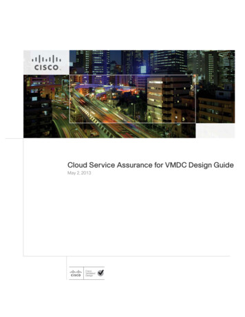
Dell Networking: Spanning-tree with VLT and vPCFigure 3 shows the reference test-bed diagram used for our first set of tests.Figure 3 : Physical and logical reference network Test-BedNotice when vPC and VLT are configured, the logical network topology it creates is a very straightforward simple pair of switches connected back to back via a quad member port-channel link.The quad member port channel link comes from the dual homed links from each switch (Cisco 5548sand Dell S4810s) where the Cisco single port-channel links are marked in red and green from eachswitch, and the Dell dual port-channel links marked by a circle icon.Once spanning-tree is turned on and the Spanning-Tree Algorithm (STA) runs, the port –channel goesinto the forwarding mode because to spanning-tree, this is a single port-channel with 4 links. It is nottwo separate individual port-channels where one needs to be blocked in order to avoid a loop in thenetwork.8
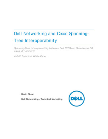
Dell Networking: Spanning-tree with VLT and vPCFigure 4 shows the reference test-bed diagram used for the second set of tests.Figure 4 : Test setup without vPC and VLTTest MethodologyUsing the network diagrams mentioned in Figure 4, our test methodology consisted of three key steps:1.Enable or disable the redundant device technology2. Configure spanning-tree and the different modes and test interoperability3. And simulate a link failure between the devicesTagged traffic was generated and transmitted from either ends of the network. Some test casessourced traffic from ports 2 or 1 to ports 3 and 4, and others sourced traffic from port 3 to ports 2 and1.NOTE:1.For all tests, the Cisco switch (N5K 1) is configured as the root of the network. All testresults obtained are based on the Cisco switch being the root switch.2. Spanning Tree is not on by default on Dell FTOS. Cisco uses RPVST as the default spanningtree mode.9
Dell Networking: Spanning-tree with VLT and vPCTwo sets of tests were performed using the following configurations:1.VLT and vPCa.RSTP Dell) and RPVST (Cisco)b. RSTP (Dell) and MST (Cisco)2. No VLT and no vPCa.PVST (Dell) and RPVST (Cisco)b. RSTP (Dell) and RPVST (Cisco)c.MSTP (Dell) and MST (Cisco)d. RSTP (Dell) and MST (Cisco)The following hardware and software was used for this exercise:Hardware Dell S4810 (2) Dell S60 (2) Cisco 5548UP (2) Traffic source : IXIA XM2 Chassis with 4-10GE ModuleSoftware FTOS-SE-9-1-0-0.bin FTOS-SC-8.3.3.9.bin Cisco 5.1(3)N2 (1)The following formulae were used to calculate the packet loss and packet loss duration: Packet Loss (Total Frames sent – (Total Frames Received))/Total Frames sent Packet Loss Duration(s) (Total Frames sent – (Total Frames Received))/Frames sent rateTests – VLT (Aggregation) and vPC (Core)Test Case #1 – RSTP (Dell S4810s) and RPVST (Cisco 5548UP)In this particular test, the Dell switches and Cisco switches have been configured with their respectivedevice redundancy technologies.RPVST is configured on the Cisco switches and on the Dell switches, RSTP is configured.Note: With VLT, RSTP is the only spanning-tree flavor supported currently.10
Dell Networking: Spanning-tree with VLT and vPCFigure 5 describes the traffic flow for the respective vlans configured and the links that will be disabled(marked with an “X”) to simulate a fail-over scenario on vlan 10. Notice N5K 1 is the primary or rootbridge for vlan 10.Figure 5 : Physical and Logical Network Topology - vlan 20Test Steps:1.Create two tagged streams with vlan id 10 being sourced from port 2 with MAC address “2”and destination ports 3 & 4 with MAC destination addresses “3” and “4” respectively.2. Ensure that tagged vlan 20 traffic from the traffic source port 2 is going through the N5K 1Cisco switch as per the diagram.3. Interface counters on N5K 2 should read zero.4. Shut down both port-channels 100 & 110 on N5K 1 to simulate a fail-over scenario and checkfor any traffic disruption. Data flow from port 2 to ports 3 and 4 now flow through the vPCport-channel to N5K 2 and down through each respective link.5.Recover both ports and check for any traffic disruption and make sure N5K 1 becomes theroot bridge.6. Shut down individual ports 1& 2 and check for any traffic disruptions.7.Repeat the steps 4 – 6, and source traffic from port 3 with destination ports 2 & 1.Results: Traffic disruption measured in micro-seconds was less than 0.02. Packet loss was less than0.0001%. The same results were achieved for all the different tests mentioned in steps 4 – 6. Figure 5is a snapshot of the test results during a fail-over and recovery from ports 1 to ports 3 & 4.11
Dell Networking: Spanning-tree with VLT and vPC Packet Loss % 0.0001 Packet Loss Duration 0.02In order to understand the results achieved, we need to dissect and take a look at the interconnectionsbetween the Cisco switches and the Dell switches. When vPC and VLT is configured on the Cisco andDell switches respectively, a 4-member port-channel link is created between the switches.From the S4810 1, Po100 is bundled with Po110 through the vlt-lag-peer port-channel command.In this case, Po100 and Po110 are bundled to form a pseudo-master-VLT channel.From the Cisco switch perspective, the four individual links are configured under the same virtual portchannel number and thus creating the 4-member port-channel link.Figure 6 shows the local and remote port channel relationship on S4810 1. In other words, shuttingdown the local port-channel on the switch does not affect its forwarding capability since the remoteport-channel member remains up and running. By shutting down Po100 locally, Po110 continues toforward the traffic since both port-channels are continuously forwarding.VLT ports, similar to vPC ports, are always in the forwarding by default as per the featureimplementation. This is not to say that VLT ports don’t go into blocking mode. If a loop is detected onthe VLT ports, they will surely go into blocking mode.Figure 6 : VLT LAG Peer Status12
Dell Networking: Spanning-tree with VLT and vPCFigure 7 and Figure 8 show the spanning-tree link status for all four switches. Notice, they are allforwarding.Figure 7: Cisco RPVST link statusFigure 8: S4810s RSTP link status13
Dell Networking: Spanning-tree with VLT and vPCFigure 9: Stream Statistics for Vlan 10The cells in red indicate the packet loss percentage and packet loss duration measurements.Test Case #2 – RSTP (Dell S4810s) and MST (Cisco 5548UP)Using the same setup as in Figure 4, we configured MSTP on the Cisco switches, and re-ran the sameset of tests as in Test #1.With RSTP and MST enabled, considering that MST runs or uses RSTP’s convergence timers, and thefact that only a single spanning-tree instance is running between the two different regions, we shouldexpect to get convergence times ranging between 1-2 seconds or possibly less.Figure 10 describes how the traffic flow sent from port 3 to ports 2 and 1 traverse the network and thelink that will be shut-down and brought up again.Notice how the traffic for port 1 flows through the root bridge and across the internal vPC channel tothe secondary switch and then finally to port 1.In addition, Figure 10 describes the initial test that will be performed by shutting down Po100 (PortChannel 100) on the Cisco N5K 1 switch.14
Dell Networking: Spanning-tree with VLT and vPCFigure 10 : Physical and Logical Network TopologyTest Steps:1.Create two tagged streams with vlan id 20 with source mac port 3, destination ports 1 and 2.2. Ensure that vlan 20 traffic from port 3 is going through the N5K 1 since this is the commonspanning-tree root bridge.3. Interface counters on N5K 2 ports 1 and 2 should read zero. The only interface on N5K 2incrementing should be the internal vPC channel and port 3 transmit counter.4. Shut down port-channel 100 on N5K 1 to simulate a fail-over scenario and check for anytraffic disruption.5.Recover Po100 on N5K 1and check for any traffic disruption and make sure N5K 1 becomesthe root bridge.6. Shut down individual ports 46 and 47 on S4810 1 and check for any traffic disruptions. Trafficshould switch-over to Po110 on S4810 2 and continue without measurable disruption7.Recover ports 46 and 47 and check for any measurable traffic disruption.Results: Great numbers. With VLT and vPC, the group of four switches created a simple pair ofswitches connected via a 4 member port-channel link. (See Logical Network Topology Figure 10). Packet Loss % 0.0001 Packet Loss Duration 0.006 seconds15
Dell Networking: Spanning-tree with VLT and vPCAs expected, because of vPC and VLT, the links between the Dell S4810s and Cisco 5548s create anactual 4 member port-channel link. This means that by shutting down Port-channel 100 on the CiscoN5K 1 traffic should not be interrupted because there are still 3 available links that are still forwarding.This is confirmed once we look at Te0/47 counters. Initially, Te0/47 reads “0” on transmit; however,when Po100 is shut down on the Cisco N5K 1 switch, Te0/47 counters begin to increment confirmingthe switch-over.Shutting down the individual links on the Dell S4810 1 switch made no difference on the results. Thisis because as far as the switch is concerned, shutting down an individual link that is part of the Portchannel is a non-issue as long as there is a redundant link. In our case, there are 3 other links availableand forwarding.Figure 11 shows a snapshot of the counters (in red) during and after switch-over failures.Figure 11: Traffic port statistics during link fail-overTests – no VLT (Aggregation) no vPC (Core)The next set of tests will focus on running different spanning-tree interations, with no vPC and VLTconfigured. The purpose of this is to demonstrate that in a typical triangle deployment, running simpleLayer 2 links with no specific vendor features; standard based spanning-tree modes interoperate withno issues.16
Dell Networking: Spanning-tree with VLT and vPCTest Case # 1 - RSTP (Dell S4810s) and RPVST (Cisco 5548UP)Figure 12, shows the traffic flow at steady state. Each Cisco N5K is a root for vlans 10 and 20respectively. The black arrow describes the traffic flow for vlans 10 and 20. See the logical spanningtree network topology. Te0/46 is forwarding and Te0/47 is being blocked. This is the normalbehavior of a having a single spanning tree instance for all vlans (Dell RSTP), on the other hand, withthe Cisco running RPVST , two different spanning tree instances are created.From the N5K 1 switch perspective, the root of vlan 20 traffic is N5K 2 and it creates a separateinstance pointing to N5K 2 as the root switch (see Figure 13). From the N5K 2 switch perspective, theroot of vlan 10 traffic is N5K 1 and it creates a separate instance pointing to N5K 1 as the root switch(see Figure 14).Figure 12: Physical Network Topology RSTP (Dell) and RPVST (Cisco)Figure 13 : Vlan 20 spanning tree instance N5K 1VLAN0020Spanning tree enabled protocol rstpRoot ID Priority 24596Address547f.eeac.13c1 N5K 2 MAC AddressCost2Port159 (Ethernet1/31)Hello Time 2 sec Max Age 20 sec Forward Delay 15 secBridge ID Priority 28692 (priority 28672 sys-id-ext 20)Address547f.eeab.dbbcHello Time 2 sec Max Age 20 sec Forward Delay 15 secInterface---------------Eth1/2Eth1/3Eth1/31Role Sts CostPrio.Nbr Type---- --- --------- -------- -------------------------------Desg FWD 2128.130 P2pDesg FWD 2128.131 P2pRoot FWD 2128.159 P2p Pointing to N5K 2 as the root switchN5K 1#17
Dell Networking: Spanning-tree with VLT and vPCFigure 14 : Vlan 10 spanning tree instance N5K 2VLAN0010Spanning tree enabled protocol rstpRoot ID Priority 24586Address547f.eeab.dbbc N5K 1 MAC AddressCost2Port159 (Ethernet1/31)Hello Time 2 sec Max Age 20 sec Forward Delay 15 secBridge ID Priority 28682 (priority 28672 sys-id-ext 10)Address547f.eeac.13c1Hello Time 2 sec Max Age 20 sec Forward Delay 15 secInterfaceRole Sts CostPrio.Nbr Type---------------- ---- --- --------- -------- -------------------------------Eth1/1Desg FWD 2128.129 P2pEth1/3Desg FWD 2128.131 P2pEth1/31Root FWD 2128.159 P2p Pointing to N5K 1 as the root switchN5K 2#Test Steps:1.Create two tagged streams with vlan id 20 with source mac port 3, destination ports 1 and 2.2. Shut down Te0/46 on S4810 1 to simulate a fail-over scenario and check for any trafficdisruption.3. Recover Te0/46 on S4810 1 and check for any traffic disruption.Results: As expected, in this particular test, there are two different spanning-tree modes, one is apurely vendor proprietary implementation (RPVST ), and the other standard based (RSTP). Because ofthis, we expected some issues in terms of interoperability. Below are the test results of this run:1.When shutting down Te0/46: Packet Loss % 0.003 Packet Loss Duration (s) 0.224When Te0/46 is disabled, the ALTR (Alternate root port Te0/47 on the S4810) moves to the forwardingmode immediately. This is the expected behavior as per the implementation of an alternate root portinside RSTP. Since the alternate root port is the backup root port, there is no BPDU exchange thattakes place within the network specified on Figure 12. Because of this the switchover and forwardingtimes are extremely fast.2. After recovering Te0/46 Packet Loss % 40-50 Packet Loss Duration 30 secondsWith RSTP, a direct message exchange takes place between point to point links. This exchangeconsists of an RSTP BPDU proposal message and an agreement message. With RPVST , the samemessage exchange takes place; however, these messages are being generated on a per-vlan basis.RPVST is a Cisco proprietary implementation and the way it works, is by generating and sendingthese exchange messages to a specific multicast address (See Figure 15 or 16) for any other vlan otherthan vlan 1, and this multicast address is understood *only* by the Cisco switch.18
Dell Networking: Spanning-tree with VLT and vPCIn the case of the test performed, the RSTP BPDUs for vlans 10 and 20 go unanswered by the DellS4810 (See Figure 15).Because of the mismatched RSTP implementations, the Cisco switches do not receive an agreementbased on their BPDU proposal message which in turn forces the Cisco switches to revert back to thelegacy spanning tree behavior and wait for at least twice the forward-delay timer (15 seconds)Figure 15 : RSTP BPDU for vlan 10RSTP BPDU FOR VLAN 10 on Port 1/2 all Cisco reserved Multicast address in red2013 Jul 19 16:50:38.073188 stp: RSTP(10): transmitting RSTP BPDU on Ethernet1/22013 Jul 19 16:50:38.073203 stp: vb vlan shim send bpdu(1977): VDC 1 Vlan 10 port Ethernet1/2enc type 1 len 422013 Jul 19 16:50:38.073225 stp: BPDU TX: vb 1 vlan 10 port Ethernet1/2 len 42 - 01000ccccccd CFGP:0000 V:02 T:02 F:0e R:60:0a:54:7f:ee:ab:db:bc 00000000 B:60:0a:54:7f:ee:ab:db:bc 8082 A:0000M:0014 H:0002 F:000f T:0000 L:0002 D:0aFigure 16 show how the Cisco N5Ks are transmitting RSTP BPDUs for the specific vlans to the specificmulticast addresses. Notice the well-known IEEE standard based address (0180.C200.0000) and theCisco reserved address (0100.0CCC.CCCD) for vlan 1. On the other hand, for vlan 10, only the Ciscoreserved address is used which the Dell S4810 simply drops.Figure 16: Cisco RPVST Spanning-Tree Debug19
Dell Networking: Spanning-tree with VLT and vPCFigure 17 shows the traffic outage duration upon restoring the port-channel link.Figure 17 : Screen shot during fail-overTest Case # 2 - PVST (Dell S4810s) and RPVST (Cisco 5548UP)Figure 15 depict the physical and logical network topology respectively. Notice how vlan 10 is beingforwarded on Te 0/46 and blocked on Te0/47, and vice-versa for vlan 20.Figure 18: Physical and logical network topology - RPVST & PVST 20
Dell Networking: Spanning-tree with VLT and vPCFigure 16 and Figure 17 show the port state on the Dell S4810 as per PVST .Figure 19: Vlan 10 S4810 link status per spanning-treeFigure 20 : Vlan 20 traffic spanning-tree21
Dell Networking: Spanning-tree with VLT and vPCTest Steps:1.Create two tagged streams with vlan id 10 and 20 with source mac port 3, destination ports 1and 2.2. Shut down Te0/46 on S4810 1 to simulate a fail-over scenario and check for any trafficdisruption.3. Recover Te0/46 on S4810 1 and check for any traffic disruption and make sure N5K 1becomes the root bridge.4. Repeat steps 2 and 3 for Te0/47 on the S4810 1 switch.Results: As expected, the blocked vlans started to forward right away upon a link failure. Differentper-VLAN spanning-tree instances were created. Upon failing the links between the S4810 1 andeach respective N5K the timers observed were: Packet Loss % 0.0 Packet Loss Duration 0.1 seconds, upon each link fail-overTest Case # 3 - RSTP (Dell S4810s) and MST (Cisco 5548UP)For this particular test, two sets of tests were performed using the following configuration:1.Default common/single spanning-tree instance created by MST and RSTP2. Create two spanning-tree instances on the Cisco switches and assign vlans 10 and 20 to eachinstance respectively and perform the test.Figure 18 describes the physical and logical spanning-tree view of the network under acommon/single spanning-tree configuration.Figure 21 : Physical and logical network topology22
Dell Networking: Spanning-tree with VLT and vPCCommon/single spanning-tree instanceThe following screen-shots show the spanning-tree link status on the Cisco switches and Dell S4810sunde
Cisco vPC - A Virtual Port-Channel (vPC) allows links that are physically connected to two different Cisco Nexus 5000 Series devices to appear as a single Port -Channel to a third device. The third device can be a Cisco Nexus 2000 Series Fabric Extender or a switch,