Transcription
Cisco 2811 and Cisco 2821 Integrated ServicesRouter with AIM-VPN/EPII-Plus FIPS 140-2Non Proprietary Security PolicyLevel 2 ValidationVersion 1.2December 14, 2005IntroductionThis document is the non-proprietary Cryptographic Module Security Policy for the Cisco 2811 andCisco 2821 Integrated Services Routers with AIM-VPN/EPII-Plus installed. This security policydescribes how the Cisco 2811 and Cisco 2821 Integrated Services Routers (Hardware Version: 2811 or2821;AIM Version: 1.0, Board Version: D0; Firmware Version: 12.3(11)T03) meet the securityrequirements of FIPS 140-2, and how to operate the router enabled in a secure FIPS 140-2 mode. Thispolicy was prepared as part of the Level 2 FIPS 140-2 validation of the Cisco 2811 or Cisco 2821Integrated Services Router.FIPS 140-2 (Federal Information Processing Standards Publication 140-2—Security Requirements forCryptographic Modules) details the U.S. Government requirements for cryptographic modules. Moreinformation about the FIPS 140-2 standard and validation program is available on the NIST website athttp://csrc.nist.gov/cryptval/.This document contains the following sections: Introduction, page 1 Cisco 2811 and Cisco 2821 Routers, page 3 Secure Operation of the Cisco 2811 or Cisco 2821 router, page 22 Related Documentation, page 24 Obtaining Documentation, page 24 Documentation Feedback, page 25 Cisco Product Security Overview, page 25Corporate Headquarters:Cisco Systems, Inc., 170 West Tasman Drive, San Jose, CA 95134-1706 USA 2005 Cisco Systems, Inc. All rights reserved.
Introduction Obtaining Technical Assistance, page 26 Obtaining Additional Publications and Information, page 28ReferencesThis document deals only with operations and capabilities of the Cisco 2811 and Cisco 2821 routers withAIM modules in the technical terms of a FIPS 140-2 cryptographic module security policy. Moreinformation is available on the routers from the following sources: The Cisco Systems website contains information on the full line of Cisco Systems routers. Pleaserefer to the following ters/index.html For answers to technical or sales related questions please refer to the contacts listed on the CiscoSystems website at www.cisco.com. The NIST Validated Modules website (http://csrc.nist.gov/cryptval) contains contact informationfor answers to technical or sales-related questions for the module.TerminologyIn this document, the Cisco 2811 and Cisco 2821 routers are referred to as the router, the module, or thesystem.Document OrganizationThe Security Policy document is part of the FIPS 140-2 Submission Package. In addition to thisdocument, the Submission Package contains: Vendor Evidence document Finite State Machine Other supporting documentation as additional referencesThis document provides an overview of the routers and explains their secure configuration andoperation. This introduction section is followed by the “Cisco 2811 and Cisco 2821 Routers” section onpage 3, which details the general features and functionality of the router. The “Secure Operation of theCisco 2811 or Cisco 2821 router” section on page 22 specifically addresses the required configurationfor the FIPS-mode of operation.With the exception of this Non-Proprietary Security Policy, the FIPS 140-2 Validation SubmissionDocumentation is Cisco-proprietary and is releasable only under appropriate non-disclosure agreements.For access to these documents, please contact Cisco Systems.2Cisco 2811 and Cisco 2821 Integrated Services Router with AIM-VPN/EPII-Plus FIPS 140-2 Non Proprietary Security PolicyOL-8664-01
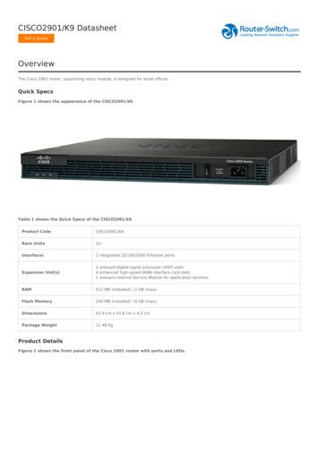
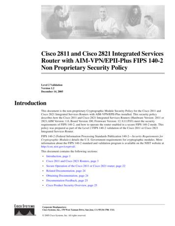
Cisco 2811 and Cisco 2821 RoutersCisco 2811 and Cisco 2821 RoutersBranch office networking requirements are dramatically evolving, driven by web and e-commerceapplications to enhance productivity and merging the voice and data infrastructure to reduce costs. TheCisco 2811 and Cisco 2821 routers provide a scalable, secure, manageable remote access server thatmeets FIPS 140-2 Level 2 requirements. This section describes the general features and functionalityprovided by the routers. The following subsections describe the physical characteristics of the routers.The Cisco 2811 Cryptographic Module Physical CharacteristicsFigure 1SYS AUXPWR PWR/ SYSACTThe Cisco 2811 router caseCFCOMPACTCONSOL1FLASHEOPTIONAL RPS INPUTDo Not Rem0ove During NetworkAUXOperation12V-48V11A4A95902100-240V 4A50/60 HzThe Cisco 2811 Router is a multiple-chip standalone cryptographic module. The router has a processingspeed of 350MHz. Depending on configuration, the installed AIM-VPN/EPII-Plus module or the IOSsoftware is used for cryptographic operations.The cryptographic boundary of the module is the device's case. All of the functionality discussed in thisdocument is provided by components within this cryptographic boundary.The interface for the router is located on the front and rear panels as shown in Figure 2 and Figure 3,respectively.Cisco 2811 Front Panel Physical Interfaces76543CONSOLESYS AUX/ SYSPWR PWR ACT21OPTIONAL RPS INPUT1CFCOMPACT FLASHAUX012V11A100-240 V 2A50/60 Hz95551Figure 2Do Not Remove During Network OperationCisco 2811 and Cisco 2821 Integrated Services Router with AIM-VPN/EPII-Plus FIPS 140-2 Non Proprietary Security PolicyOL-8664-013
Cisco 2811 and Cisco 2821 RoutersCisco 2811 Rear Panel Physical Interfaces786HWIC2HWIC3HWIC111AA ACTS SPEEDFE 0/14AFH SWI LC0SLPVDM15A FDXA LINKFE 0/0FPVDM03AIM1AIM0295556Figure 3The Cisco 2811 router features a console port, an auxiliary port, two Universal Serial Bus (USB) ports,four high-speed WAN interface card (HWIC) slots, two10/100 Gigabit Ethernet RJ45 ports, an EnhancedNetwork Module (ENM) slot, and a Compact Flash (CF) drive. The Cisco 2811 router supports onesingle-width network module, four single-width or two double-width HWICs, two slots forAIM-VPN/BPII-Plus cards1, two internal packet voice data modules (PVDMs), two fast Ethernetconnections, and 16 ports of IP phone power output. Figure 2 shows the front panel and Figure 3 showsthe rear panel. The front panel contains 4 LEDs that output status data about the system power, auxiliarypower, system activity, and compact flash busy status. The back panel consists of 12 LEDs: two Ethernetactivity LEDs, two duplex LEDs, two speed LEDs, two link LEDs, two PVDM LEDs, and two AIMLEDs.The front panel contains the following: (1) Power inlet (2) Power switch (3) Optional RPS input (4) Console and auxiliary ports (5) USB ports (6) CF drive (7) LEDs described in table 1.The back panel contains the following: (1) Ground connector (2) and (3) Ethernet ports and LEDs (4)-(7) HWIC slots (8) ENM slot.Table 1 and Table 2 provide more detailed information conveyed by the LEDs on the front and rear panelof the router:Table 1Cisco 2811 Front Panel IndicatorsNameStateDescriptionSystem PowerOffPower offBlinking GreenROMMON modeSolid GreenOperating normallySolid OrangeSystem Error Detected1. The security policy covers the configuration in which one AIM card is used.4Cisco 2811 and Cisco 2821 Integrated Services Router with AIM-VPN/EPII-Plus FIPS 140-2 Non Proprietary Security PolicyOL-8664-01
Cisco 2811 and Cisco 2821 RoutersTable 1Cisco 2811 Front Panel Indicators (Continued)Auxiliary Power OffActivityCompact FlashTable 2-48V PS and RPS not presentSolid Green-48V PS or RPS present and functionalSolid Orange-48V PS or RPS present and failure detectedOffNo interrupts or packet transfer occurringBlinking GreenSystem is servicing interruptsSolid GreenSystem is actively transferring packetsOffNo ongoing accesses, eject permittedSolid GreenDevice is busy, do not ejectCisco 2811 Rear Panel IndicatorsNameStateDescriptionPVDM1OffPVDM1 not installedSolid GreenPVDM1 installed and initializedSolid OrangePVDM1 installed and initialized errorOffPVDM0 not installedSolid GreenPVDM0 installed and initializedSolid OrangePVDM0 installed and initialized errorOffAIM1 not installedSolid GreenAIM1 installed and initializedSolid OrangeAIM1 installed and initialized errorOffAIM0 not installedSolid GreenAIM0 installed and initializedSolid OrangeAIM0 installed and initialized errorPVDM0AIM1AIM0Table 3 describes the meaning of Ethernet LEDs on the rear panel:Table 3Cisco 2811 Ethernet IndicatorsNameStateDescriptionActivityOffNot receiving packetsSolid/BlinkingGreenReceiving packetsOffHalf-DuplexSolid GreenFull-DuplexDuplexCisco 2811 and Cisco 2821 Integrated Services Router with AIM-VPN/EPII-Plus FIPS 140-2 Non Proprietary Security PolicyOL-8664-015
Cisco 2811 and Cisco 2821 RoutersTable 3Cisco 2811 Ethernet IndicatorsSpeedOne Blink Green10 MbpsTwo Blink Green100 MbpsOffNo link establishedSolid GreenEthernet link is establishedLinkThe physical interfaces are separated into the logical interfaces from FIPS 140-2 as described in theTable 4:Table 4Cisco 2811 FIPS 140-2 Logical InterfacesRouter Physical InterfaceFIPS 140-2 Logical Interface10/100 Ethernet LAN PortsData Input InterfaceHWIC PortsConsole PortAuxiliary PortENM Slot10/100 Ethernet LAN PortsData Output InterfaceHWIC PortsConsole PortAuxiliary PortENM Slot10/100 Ethernet LAN PortsControl Input InterfaceHWIC PortsPower SwitchConsole PortAuxiliary PortENM Slot10/100 Ethernet LAN Port LEDsStatus Output InterfaceAIM LEDsPVDM LEDsPower LEDActivity LEDsAuxiliary LEDCompact Flash LEDConsole PortAuxiliary PortMain Power PlugPower InterfaceRedundant Power Supply Plug6Cisco 2811 and Cisco 2821 Integrated Services Router with AIM-VPN/EPII-Plus FIPS 140-2 Non Proprietary Security PolicyOL-8664-01
Cisco 2811 and Cisco 2821 RoutersThere are two USB ports but they are not supported currently. The ports will be supported in the futurefor smartcard or token reader.The CF card that stored the IOS image is considered an internal memory module, because the IOS imagestored in the card may not be modified or upgraded. The card itself must never be removed from thedrive. Tamper evident seal will be placed over the card in the drive.The Cisco 2821 Cryptographic Module Physical CharacteristicsFigure 4The Cisco 2821 router caseSYS AUXPWR PWR/ SYSACTCFCOMPACTOPTIONALRPS12V-48VINPUTDo Not Remove DurinCONSOL1FLASHg NetworkE0AUXOperation11A4A95903100-240V 4A50/60 HzThe Cisco 2821 router a multiple-chip standalone cryptographic module. The router has a processingspeed of 350MHz. Depending on configuration, either the installed AIM-VPN/EPII-Plus card or the IOSsoftware is used for cryptographic operations.The cryptographic boundary of the module is the device's case. All of the functionality discussed in thisdocument is provided by components within this cryptographic boundary.The interfaces for the router are located on the front and rear panel as shown in Figure 5and Figure 6,respectively.Figure 5Cisco 2821 Front Panel Physical Interfaces7654321CONSOLESYS AUX/ SYSPWR PWR ACTCF1COMPACT FLASHAUX0Do Not Remove During Network OperationOPTIONAL RPS INPUT100-240 V 3A50/60 Hz18ACisco 2811 and Cisco 2821 Integrated Services Router with AIM-VPN/EPII-Plus FIPS 140-2 Non Proprietary Security PolicyOL-8664-019555312V7
Cisco 2811 and Cisco 2821 RoutersFigure 6Cisco 2821 Rear Panel Physical Interfaces2A ACTS SPEEDGE 0/1A61A FDXA LINKGE 0/04537AFFSSLLEVM 2 ONLYAIM1AIM095572PVDM2 PVDM1 PVDM0189The Cisco 2821 router features a console port, an auxiliary port, two Universal Serial Bus (USB) ports,four high-speed WAN interface card (HWIC) slots, two10/100 Gigabit Ethernet RJ45 ports, a EnhancedNetwork Module (ENM) slot, a Voice Network Module (VeNoM) slot, and a Compact Flash (CF) drive.The Cisco 2821 router supports one single-width network module, four single-width or twodouble-width HWICs, has two slots for AIM-VPN/BPII-Plus cards1, three internal packet voice datamodules (PVDMs), two fast Ethernet connections, and 16 ports of IP phone power output. Figure 5shows the front panel and Figure 6 shows the rear panel. The front panel contains 4 LEDs that outputstatus data about the system power, auxiliary power, system activity, and compact flash busy status. Theback panel consists of 13 LEDs: two Ethernet activity LEDs, two duplex LEDs, two speed LEDs, twolink LEDs, three PVDM LEDs, and two AIM LEDs.The front panel contains the following: (1) Power inlet (2) Power switch (3) Console and auxiliary ports (4) USB ports (5) CF drive (6) LEDs described in table 1. (7) Optional RPS inputThe back panel contains the following: (1) GE 0 port (2) GE 1 port (3) HWIC 0 slot (4) HWIC 1 slot (5) HWIC 2 slot (6) HWIC 3 slot (7) VeNoM slot (8) ENM slot (9) Ground connector1. The security policy covers the configuration in which one AIM card is used.8Cisco 2811 and Cisco 2821 Integrated Services Router with AIM-VPN/EPII-Plus FIPS 140-2 Non Proprietary Security PolicyOL-8664-01
Cisco 2811 and Cisco 2821 RoutersTable 5 and Table 6 provide more detailed information conveyed by the LEDs on the front and rear panelof the router:Table 5Cisco 2821 Front Panel IndicatorsNameStateDescriptionSystem PowerOffPower offBlinking GreenROMMON modeSolid GreenOperating normallySolid OrangeSystem Error DetectedAuxiliary Power OffActivityCompact FlashTable 6-48V PS and RPS not presentSolid Green-48V PS or RPS present and functionalSolid Orange-48V PS or RPS present and failure detectedOffNo interrupts or packet transfer occurringBlinking GreenSystem is servicing interruptsSolid GreenSystem is actively transferring packetsOffNo ongoing accesses, eject permittedSolid GreenDevice is busy, do not ejectCisco 2821 Rear Panel IndicatorsNameStateDescriptionPVDM2OffPVDM2 not installedSolid GreenPVDM2 installed and initializedSolid OrangePVDM2 installed and initialized errorOffPVDM1 not installedSolid GreenPVDM1 installed and initializedSolid OrangePVDM1 installed and initialized errorOffPVDM0 not installedSolid GreenPVDM0 installed and initializedSolid OrangePVDM0 installed and initialized errorOffAIM1 not installedSolid GreenAIM1 installed and initializedSolid OrangeAIM1 installed and initialized errorOffAIM0 not installedSolid GreenAIM0 installed and initializedSolid OrangeAIM0 installed and initialized errorPVDM1PVDM0AIM1AIM0Table 7 describes the meaning of Ethernet LEDs on the front panel:Cisco 2811 and Cisco 2821 Integrated Services Router with AIM-VPN/EPII-Plus FIPS 140-2 Non Proprietary Security PolicyOL-8664-019
Cisco 2811 and Cisco 2821 RoutersTable 7Cisco 2821 Ethernet IndicatorsNameStateActivityOffNot receiving packetsSolid/Blinking GreenReceiving packetsOffHalf-DuplexSolid GreenFull-DuplexOne Blink Green10 MbpsTwo Blink Green100 MbpsOffNo link establishedSolid GreenEthernet link is establishedDuplexSpeedLinkDescriptionThe physical interfaces are separated into the logical interfaces from FIPS 140-2 as described in theTable 8:Table 8Cisco 2821 FIPS 140-2 Logical InterfacesRouter Physical InterfaceFIPS 140-2 Logical Interface10/100 Ethernet LAN PortsData Input InterfaceHWIC PortsConsole PortAuxiliary PortENM SlotVeNoM Slot10/100 Ethernet LAN PortsData Output InterfaceHWIC PortsConsole PortAuxiliary PortENM SlotVeNoM Slot10/100 Ethernet LAN PortsControl Input InterfaceHWIC PortsPower SwitchConsole PortAuxiliary PortENM Slot10Cisco 2811 and Cisco 2821 Integrated Services Router with AIM-VPN/EPII-Plus FIPS 140-2 Non Proprietary Security PolicyOL-8664-01
Cisco 2811 and Cisco 2821 RoutersTable 8Cisco 2821 FIPS 140-2 Logical Interfaces (Continued)10/100 Ethernet LAN Port LEDsStatus Output InterfaceAIM LEDsPVDM LEDsPower LEDActivity LEDsAuxiliary LEDCompact Flash LEDConsole PortAuxiliary PortMain Power PlugPower InterfaceRedundant Power Supply PlugThere are two USB ports but they are not supported currently. The ports will be supported in the futurefor smartcard or token reader.The CF card that stored the IOS image is considered an internal memory module. The reason is the IOSimage stored in the card cannot be modified or upgraded. The card itself must never be removed fromthe drive. Tamper evident seal will be placed over the card in the drive.Roles and ServicesAuthentication to the Cisco 2811 and Cisco 2821 is role-based. There are two main roles in the routerthat operators can assume: the Crypto Officer role and the User role. The administrator of the routerassumes the Crypto Officer role in order to configure and maintain the router using Crypto Officerservices, while the Users exercise only the basic User services. The module supports RADIUS andTACACS for authentication. A complete description of all the management and configurationcapabilities of the router can be found in the Performing Basic System Management manual and in theonline help for the router.User ServicesUsers enter the system by accessing the console port with a terminal program or via IPSec protectedtelnet or SSH session to a LAN port. The IOS prompts the User for username and password. If thepassword is correct, the User is allowed entry to the IOS executive program.The services available to the User role consist of the following: Status Functions—View state of interfaces and protocols, version of IOS currently running. Network Functions—Connect to other network devices through outgoing telnet, PPP, etc. andinitiate diagnostic network services (i.e., ping, mtrace). Terminal Functions—Adjust the terminal session (e.g., lock the terminal, adjust flow control). Directory Services—Display directory of files kept in flash memory.Cisco 2811 and Cisco 2821 Integrated Services Router with AIM-VPN/EPII-Plus FIPS 140-2 Non Proprietary Security PolicyOL-8664-0111
Cisco 2811 and Cisco 2821 RoutersCrypto Officer ServicesDuring initial configuration of the router, the Crypto Officer password (the “enable” password) isdefined. A Crypto Officer can assign permission to access the Crypto Officer role to additional accounts,thereby creating additional Crypto Officers.The Crypto Officer role is responsible for the configuration and maintenance of the router. The CryptoOfficer services consist of the following: Configure the router—Define network interfaces and settings, create command aliases, set theprotocols the router will support, enable interfaces and network services, set system date and time,and load authentication information. Define Rules and Filters—Create packet Filters that are applied to User data streams on eachinterface. Each Filter consists of a set of Rules, which define a set of packets to permit or deny basedon characteristics such as protocol ID, addresses, ports, TCP connection establishment, or packetdirection. View Status Functions—View the router configuration, routing tables, active sessions, use gets toview SNMP MIB statistics, health, temperature, memory status, voltage, packet statistics, reviewaccounting logs, and view physical interface status. Manage the router—Log off users, shutdown or reload the router, manually back up routerconfigurations, view complete configurations, manage user rights, and restore router configurations. Set Encryption/Bypass—Set up the configuration tables for IP tunneling. Set keys and algorithmsto be used for each IP range or allow plaintext packets to be set from specified IP address.Physical SecurityThe router is entirely encased by a metal, opaque case. The rear of the unit contains HWIC/WIC/VICconnectors, LAN connectors, a CF drive, power connector, console connector, auxiliary connector, USBport, and fast Ethernet connectors. The front of the unit contains the system status and activity LEDs.The top, side, and front portion of the chassis can be removed to allow access to the motherboard,memory, AIM slot, and expansion slots.Once the router has been configured in to meet FIPS 140-2 Level 2 requirements, the router cannot beaccessed without signs of tampering. To seal the system, apply serialized tamper-evidence labels asfollows:To apply serialized tamper-evidence labels to the Cisco 2811:12Step 1Clean the cover of any grease, dirt, or oil before applying the tamper evidence labels. Alcohol-basedcleaning pads are recommended for this purpose. The temperature of the router should be above 10 C.Step 2The tamper evidence label should be placed so that one half of the label covers the front panel and theother half covers the enclosure.Step 3The tamper evidence label should be placed over the CF card in the slot so that any attempt to removethe card will show sign of tampering.Step 4The tamper evidence label should be placed so that the one half of the label covers the enclosure and theother half covers the port adapter slot.Cisco 2811 and Cisco 2821 Integrated Services Router with AIM-VPN/EPII-Plus FIPS 140-2 Non Proprietary Security PolicyOL-8664-01
Cisco 2811 and Cisco 2821 RoutersStep 5The tamper evidence label should be placed so that the one half of the label covers the enclosure and theother half covers the rear panel.Step 6The labels completely cure within five minutes.Figure 7 and Figure 8 show the tamper evidence label placements for the Cisco 2811.Figure 7Cisco 2811 Tamper Evident Label Placement (Back View)Figure 8Cisco 2811 Tamper Evident Label Placement (Front View)To apply serialized tamper-evidence labels to the Cisco 2821:Step 1Clean the cover of any grease, dirt, or oil before applying the tamper evidence labels. Alcohol-basedcleaning pads are recommended for this purpose. The temperature of the router should be above 10 C.Step 2The tamper evidence label should be placed so that one half of the label covers the front panel and theother half covers the enclosure.Step 3The tamper evidence label should be placed over the CF card in the slot so that any attempt to removethe card will show sign of tampering.Step 4The tamper evidence label should be placed so that the one half of the label covers the enclosure and theother half covers the port adapter slot.Cisco 2811 and Cisco 2821 Integrated Services Router with AIM-VPN/EPII-Plus FIPS 140-2 Non Proprietary Security PolicyOL-8664-0113
Cisco 2811 and Cisco 2821 RoutersStep 5The tamper evidence label should be placed so that the one half of the label covers the enclosure and theother half covers the rear panel.Step 6The labels completely cure within five minutes.Figure 9 and Figure 10 show the tamper evidence label placements for the Cisco 2821.Figure 9Cisco 2821 Tamper Evident Label Placement (Back View)Figure 10Cisco 2821 Tamper Evident Label Placement (Front View)The tamper evidence seals are produced from a special thin gauge vinyl with self-adhesive backing. Anyattempt to open the router will damage the tamper evidence seals or the material of the module cover.Since the tamper evidence seals have non-repeated serial numbers, they can be inspected for damage andcompared against the applied serial numbers to verify that the module has not been tampered. Tamperevidence seals can also be inspected for signs of tampering, which include the following: curled corners,bubbling, crinkling, rips, tears, and slices. The word “OPEN” may appear if the label was peeled back.Cryptographic Key ManagementThe router securely administers both cryptographic keys and other critical security parameters such aspasswords. The tamper evidence seals provide physical protection for all keys. All keys are alsoprotected by the password-protection on the Crypto Officer role login, and can be zeroized by the CryptoOfficer. All zeroization consists of overwriting the memory that stored the key. Keys are exchanged andentered electronically or via Internet Key Exchange (IKE).14Cisco 2811 and Cisco 2821 Integrated Services Router with AIM-VPN/EPII-Plus FIPS 140-2 Non Proprietary Security PolicyOL-8664-01
Cisco 2811 and Cisco 2821 RoutersThe routers support the following FIPS 140-2 approved algorithm implementations: Software (IOS) implementations– AES– DES (for legacy use only - transitional phase only – valid until May 19th, 2007)– 3DES– SHA-1– HMAC-SHA-1– X9.31 PRNG AIM module implementations– AES– DES (for legacy use only - transitional phase only – valid until May 19th, 2007)– 3DES– SHA-1– HMAC-SHA-1The routers also support the following algorithms which are not FIPS 140-2 approved: MD5,MD5-HMAC, RSA and DH.The router is in the approved mode of operation whenonly FIPS 140-2 approved algorithms are used(except DH which is allowed in the approved mode for key establishment despite being non-approved).Note: The module supports DH key sizes of 1024 and 1536 bits. Therefore, DH provides 80-bit and96-bit of encryption strength per NIST 800-57.The module contains a HiFn 7814-W cryptographic accelerator chip, integrated in the AIM card. Unlessthe AIM card is disabled by the Crypto Officer with the “no crypto engine aim” command, the HiFn7814-W provides the cryptographic implementations listed above. However, all RSA operations areprohibited by policy.The module supports two types of key management schemes: Pre-shared key exchange via electronic key entry. DES/3DES/AES key and HMAC-SHA-1 key areexchanged and entered electronically. Internet Key Exchange method with support for pre-shared keys exchanged and enteredelectronically.– The pre-shared keys are used with Diffie-Hellman key agreement technique to derive DES,3DES or AES keys.– The pre-shared key is also used to derive HMAC-SHA-1 key.The module supports the commercially available Diffie-Hellman method of key establishment. SeeDocument 7A, Cisco IOS Reference Guide.All pre-shared keys are associated with the CO role that created the keys, and the CO role is protectedby a password. Therefore, the CO password is associated with all the pre-shared keys. The CryptoOfficer needs to be authenticated to store keys. All Diffie-Hellman (DH) keys agreed upon for individualtunnels are directly associated with that specific tunnel only via the IKE protocol.Key Zeroization:Each key can be zeroized by sending the “no” command prior to the key function commands. This willzeroize each key from the DRAM, the running configuration.Cisco 2811 and Cisco 2821 Integrated Services Router with AIM-VPN/EPII-Plus FIPS 140-2 Non Proprietary Security PolicyOL-8664-0115
Cisco 2811 and Cisco 2821 Routers“Clear Crypto IPSec SA” will zeroize the IPSec DES/3DES/AES session key (which is derived usingthe Diffie-Hellman key agreement technique) from the DRAM. This session key is only available in theDRAM; therefore this command will completely zeroize this key. The following command will zeroizethe pre-shared keys from the DRAM: no set session-key inbound ah spi hex-key-data no set session-key outbound ah spi hex-key-data no set session-key inbound esp spi cipher hex-key-data [authenticator hex-key-data] no set session-key outbound esp spi cipher hex-key-data [authenticator hex-key-data]The DRAM running configuration must be copied to the start-up configuration in NVRAM in order tocompletely zeroize the keys.The following commands will zeroize the pre-shared keys from the DRAM: no crypto isakmp key key-string address peer-address no crypto isakmp key key-string hostname peer-hostnameThe DRAM running configuration must be copied to the start-up configuration in NVRAM in order tocompletely zeroize the keys.The module supports the following keys and critical security parameters (CSPs).Table 9Cryptographic Keys and CSPsNameAlgorithmDescriptionStoragePRNG SeedX9.31This is the seed for X9.31 PRNG. This CSP isstored in DRAM and updated periodically afterthe generation of 400 bytes – after this it isreseeded with router-derived entropy; hence, it iszeroized periodically. Also, the operator can turnoff the router to zeroize this CSP.DRAM(plaintext)Automatically every400 bytes, or turn offthe router.Diffie Hellman DHprivateexponentThe private exponent used in Diffie-Hellman(DH) exchange. Zeroized after DH shared secrethas been generated.DRAM(plaintext)Automatically aftershared secret generated.Diffie Hellman DHpublic keyThe public key used in Diffie-Hellman (DH)exchange as part of IKE. Zeroized after the DHshared secret has been generated.DRAM(plaintext)Automatically aftershared secret generated.skeyidKeyedSHA-1Value derived from the shared secret within IKEexchange. Zeroized when IKE session isterminated.DRAM(plaintext)Automatically after IKEsession terminated.skeyid dKeyedSHA-1The IKE key derivation key for non ISAKMPsecurity associations.DRAM(plaintext)Automatically after IKEsession terminated.skeyid aHMACSHA-1The ISAKMP security association authenticationkey.DRAM(plaintext)Automatically after IKEsession terminated.skeyid eDES/TDES The ISAKMP security association encryption key. DRAM/AES(plaintext)Automatically after IKEsession terminated.IKE sessionencrypt keyDES/TDES The IKE session encrypt key./AESAutomatically after IKEsession terminated.16DRAM(plaintext)ZeroizationMethodCisco 2811 and Cisco 2821 Integrated Services Router with AIM-VPN/EPII-Plus FIPS 140-2 Non Proprietary Security PolicyOL-8664-01
Cisco 2811 and Cisco 2821 RoutersTable 9Cryptographic Keys and CSPs (Continued)IKE sessionauthenticationkeyHMACSHA-1The IKE session authentication key.ISAKMPpresharedSecretThe key used to generate IKE skeyid duringNVRAMpreshared-key authentication. “no crypto isakmp (plaintext)key” command zeroizes it. This key can have twoforms based on whether the key is related to thehostname or the IP address.IKE hash keyHMACSHA-1This key generates the IKE shared secret keys.This key is zeroized after generating those keys.secret 1 0 0DRAM(plaintext)Automatically after IKEsession terminated.“# no crypto isakmpkey”DRAM(plaintext)The fixed key used in Cisco vendor ID generation. NVRAMThis key is embedded in the module binary image (plaintext)and can be deleted by erasing the Flash.IPSecDES/TDES The IPSec encryption key. Zeroized when IPSecencryption key /AESsession is terminated.DRAM(plaintext)Automatically whenIPSec text)Automatically whenIPSec sessionterminated.HMACSHA-1The IPSec authentication key. The zeroization isthe same as above.Configuration AESencryption keyThe key used to encrypt values of theNVRAMconfiguration file. This key is zeroized when the (plaintext)“no key config-key” is issued. Note th
Figure 1 The Cisco 2811 router case The Cisco 2811 Router is a multiple-chip standalone cryptographic module. The router has a processing speed of 350MHz. Depending on configuration, the installed AIM-VPN/EPII-Plus module or the IOS software is used for cryptographic operations. The cr