Transcription
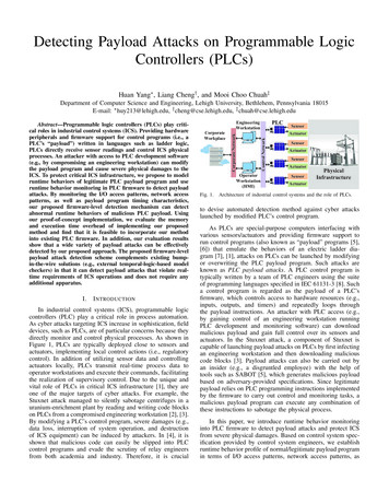
Detecting Payload Attacks on Programmable LogicControllers (PLCs)Huan Yang , Liang Cheng† , and Mooi Choo Chuah‡Department of Computer Science and Engineering, Lehigh University, Bethlehem, Pennsylvania 18015E-mail: huy213@lehigh.edu, † cheng@cse.lehigh.edu, ‡ chuah@cse.lehigh.eduI.I NTRODUCTIONIn industrial control systems (ICS), programmable logiccontrollers (PLC) play a critical role in process automation.As cyber attacks targeting ICS increase in sophistication, fielddevices, such as PLCs, are of particular concerns because theydirectly monitor and control physical processes. As shown inFigure 1, PLCs are typically deployed close to sensors andactuators, implementing local control actions (i.e., regulatorycontrol). In addition of utilizing sensor data and controllingactuators locally, PLCs transmit real-time process data tooperator workstations and execute their commands, facilitatingthe realization of supervisory control. Due to the unique andvital role of PLCs in critical ICS infrastructure [1], they areone of the major targets of cyber attacks. For example, theStuxnet attack managed to silently sabotage centrifuges in auranium-enrichment plant by reading and writing code blockson PLCs from a compromised engineering workstation [2], [3].By modifying a PLC’s control program, severe damages (e.g.,data loss, interruption of system operation, and destructionof ICS equipment) can be induced by attackers. In [4], it isshown that malicious code can easily be slipped into PLCcontrol programs and evade the scrutiny of relay engineersfrom both academia and industry. Therefore, it is crucialOperatorWorkstation(HMI)Fig. 1.SensorActuatorControl Corporate NetworkAbstract—Programmable logic controllers (PLCs) play critical roles in industrial control systems (ICS). Providing hardwareperipherals and firmware support for control programs (i.e., aPLC’s “payload”) written in languages such as ladder logic,PLCs directly receive sensor readings and control ICS physicalprocesses. An attacker with access to PLC development software(e.g., by compromising an engineering workstation) can modifythe payload program and cause severe physical damages to theICS. To protect critical ICS infrastructure, we propose to modelruntime behaviors of legitimate PLC payload program and useruntime behavior monitoring in PLC firmware to detect payloadattacks. By monitoring the I/O access patterns, network accesspatterns, as well as payload program timing characteristics,our proposed firmware-level detection mechanism can detectabnormal runtime behaviors of malicious PLC payload. Usingour proof-of-concept implementation, we evaluate the memoryand execution time overhead of implementing our proposedmethod and find that it is feasible to incorporate our methodinto existing PLC firmware. In addition, our evaluation resultsshow that a wide variety of payload attacks can be effectivelydetected by our proposed approach. The proposed firmware-levelpayload attack detection scheme complements existing bumpin-the-wire solutions (e.g., external temporal-logic-based modelcheckers) in that it can detect payload attacks that violate realtime requirements of ICS operations and does not require anyadditional alInfrastructureActuatorArchitecture of industrial control systems and the role of PLCs.to devise automated detection method against cyber attackslaunched by modified PLC’s control program.As PLCs are special-purpose computers interfacing withvarious sensors/actuators and providing firmware support torun control programs (also known as “payload” programs [5],[6]) that emulate the behaviors of an electric ladder diagram [7], [1], attacks on PLCs can be launched by modifyingor overwriting the PLC payload program. Such attacks areknown as PLC payload attacks. A PLC control program istypically written by a team of PLC engineers using the suiteof programming languages specified in IEC 61131-3 [8]. Sucha control program is regarded as the payload of a PLC’sfirmware, which controls access to hardware resources (e.g.,inputs, outputs, and timers) and repeatedly loops throughthe payload instructions. An attacker with PLC access (e.g.,by gaining control of an engineering workstation runningPLC development and monitoring software) can downloadmalicious payload and gain full control over its sensors andactuators. In the Stuxnet attack, a component of Stuxnet iscapable of launching payload attacks on PLCs by first infectingan engineering workstation and then downloading maliciouscode blocks [3]. Payload attacks can also be carried out byan insider (e.g., a disgruntled employee) with the help oftools such as SABOT [5], which generates malicious payloadbased on adversary-provided specifications. Since legitimatepayload relies on PLC programming instructions implementedby the firmware to carry out control and monitoring tasks, amalicious payload program can execute any combination ofthese instructions to sabotage the physical process.In this paper, we introduce runtime behavior monitoringinto PLC firmware to detect payload attacks and protect ICSfrom severe physical damages. Based on control system specification provided by control system engineers, we establishruntime behavior profile of normal/legitimate payload programin terms of I/O access patterns, network access patterns, as
well as payload program timing characteristics. When a newlyupdated payload program is downloaded into a PLC (eitherby an attacker or by a trusted control system engineer), itsruntime behavior data is collected by the PLC firmware. Whenabnormal behaviors are observed by the firmware, executionof the payload program is terminated so that abnormal controlsignals will not be sent to actuators. The contributions of ourwork are as follows: We introduce runtime behavior monitoring into PLCfirmware to enable automated detection of PLC payload attacks. In contrast to existing detection methodsbased on linear temporal logic, our proposed approachcan identify attacks that violate real-time requirementsof an ICS and does not require the introductionof bump-in-the-wire apparatus between engineeringworkstation and PLCs. We present a proof-of-concept implementation of thefirmware-level payload attack detection scheme onARM R Cortex R -M4F microcontrollers. Our evaluation results show that the proposed approach can detect a wide variety of payload attacks revealed by priorresearch [4] and reported cyber-security incidents. Furthermore, we evaluate the overhead of implementing the proposed detection method and find that it isfeasible to incorporate our scheme on microcontrollersused by existing PLCs to detect payload attacks.II.R ELATED W ORKA. Programmable Logic Controller (PLC) and Payload Program Execution ModelA programmable logic controller (PLC) is a specialpurpose computer designed to replace relay panels and controla physical process [7]. Figure 2 presents the general hardware and software architecture of PLCs. There are severalimportant characteristics that distinguish PLCs from personalcomputers [9]: PLCs are designed to operate in harsh industrialenvironments and are programmed in relay ladder logic orother PLC programming languages [8]. In addition, a PLC executes a simple payload program in a sequential fashion. Oncedeployed in an ICS, a PLC continuously collects readings fromsensors connected to its inputs, runs the PLC payload program,and generates outputs that control the physical process. Asshown in Fig. 1, PLC control program can be developedon engineering workstations using programming software thatsupports ladder logic or other PLC programming languagesand downloaded to target PLC for execution. Operator ofan ICS may monitor and control the physical process via ahuman-machine interface (HMI), which communicates withPLCs to receive real-time process data and issue controlcommands.To control and monitor physical process, a PLC’s firmwareimplements input and output image tables as well as a programscan cycle [7], [9]. A program scan cycle consists of inputscan, program scan, output scan, and housekeeping phases,which are shown in Fig. 3. After system start-up, a PLCrepeatedly walks through the four phases of the programscan cycle as follows: First, in the input scan phase, thePLC payload/control programInput image tableI/OFig. 2.Driver libraryTimer Counter CPUControllogicOutput image table FirmwareMemoryCommunicationPLCHardwareGeneral PLC hardware and software architecture.PLC firmware samples the I/O pin values and writes theminto the input image table. Then, in the program scan phase,instructions in the payload program are executed one by oneusing values stored in the input image table. Output values aregenerated during this phase and written into the output imagetable. Next, in the output scan phase, values in the outputimage table are transferred to the external output terminals,making control actions specified in the payload program takeeffect. Finally, in the housekeeping phase, internal checks onmemory and system operation are performed. Additionally,communication requests originated from other hosts (e.g., theHMI) or generated by the payload program itself are alsoserviced before the next program scan cycle starts.B. PLC Ladder LogicMany widely-used PLC programming languages are standardized in IEC 61131-3 [8] and ladder logic is the mostcommonly used one [9] since it is straightforward to controlsystem engineers who prefer to define control actions in termsof relay contacts and coils. Instructions specified by ladderlogic have their own symbolic representation. A PLC payloadprogram written in ladder logic has one or more ladderformatted schematic diagrams. Within each diagram, ladderlogic instructions are organized into rungs. Each rung maycontain multiple ladder logic instructions, which are evaluatedfrom left to right. Instructions on the left of a rung testinput conditions or outputs generated by other rungs, andinstructions on the right generate rung outputs. Multiple inputcondition checks can be placed in tandem, and the input logicevaluates to true if and only if all input conditions are true.Parallel branches can be used on a rung to accommodatemore than one input condition combinations. The rung logicis evaluated to true as long as one of the branches forms atrue logic path. When multiple output branches are present ona rung, a true logic path controls multiple outputs.Fig. 4 shows a sample subroutine of a ladder logic programconsisting of three rungs. The “XIC” instruction on the firstrung examines if an input is true. If so, the instruction evaluatesto true. The “OTE” instruction energizes a specified output bit.Input condition of the first rung first checks if input bit I:0/4 mstart-upFig. 3.PLC payload program execution model.
I:0/4I:0/0O:2/1XICI:0/3O:2/2OTEJSRJump To SubroutineSBR File Number U:7ENDFig. 4.A sample ladder logic program with three rungs.I:0/3 is true and then checks if I:0/0 bit is true. The output ofthis rung controls both output bits, i.e., O:2/1 and O:2/2. Thesecond rung’s input condition is always true, so the subroutinein file U:7 is executed. Note that the subroutine is essentiallyanother ladder logic diagram. When the subroutine returns, thesecond rung completes and the third rung is evaluated, whichsignals the end of the payload program. Note that hierarchicaladdressing is used in ladder logic program to specify thedata type, slot number, and bit position of PLC data andperipherals [9]. For example, I:0/4 is the fifth bit of binaryinput slot 0 (with the first bit being I:0/0). For analog I/Os, thehierarchical address is slightly different. For example, O:2.0is an analog output on the output module installed on slot 2,and the output value is written to the first (zero-indexed) wordof its allocated memory.Ladder logic provides a wide range of instructions forPLC engineers to specify control actions. Bit instructionsexamine status of individual input/internal bit or control asingle output bit. Word instructions, such as mathematicaloperations, data transfer, and logical operations, operate ondata words or registers. Program control instructions, suchas subroutine invocation and return, control the executionflow of the payload program. For control program of largeand complex ICS, subroutines are frequently used to betterorganize the instructions and enhancement maintainability. Inaddition, communication instructions allow a PLC to communicate with other hosts via a particular ICS network protocol.From the perspective of PLC control program development, amalicious payload is essentially a combination of legitimatePLC programming instructions causing disastrous impacts onan ICS. In this paper, we focus on detecting payload attacksimplemented via ladder logic, but the proposed techniques areapplicable to attacks written in other languages [8] as wellbecause different PLC programming languages can be used toimplement the same control system specifications [9].C. Firmware vs. Payload AttacksAs revealed by Fig. 2, both the PLC firmware and itspayload program can become the target of cyber attacks. Anattacker can reverse-engineer and modify the firmware on aPLC to launch firmware attacks. In this case, even thougha legitimate payload program is downloaded to the PLC, itsexecution will still be monitored and/or intercepted by themodified firmware. In [10], a rootkit is developed on theCODESYS PLC runtime to intercept I/O operations of thepayload program. When the payload wants to read or writea certain I/O pin, interrupt handler installed by the attackeris called first, within which the attacker can reconfigure theI/O pins or modify values to be read/written. In [6], a moreadvanced rootkit is developed for an Allen Bradley CompactLogix PLC firmware. In addition to intercepting PLC inputsand outputs at the firmware, it incorporates physical-processawareness and always presents modified sensor measurements,hoaxing ICS operator in front of the HMI to think that thesystem runs normally.Firmware attacks typically requires detailed knowledge ontarget PLC’s hardware components and reverse-engineeringof its firmware because PLCs are closed-source embeddeddevices [11]. An attacker needs to install the rootkit on PLCseither via the built-in remote firmware update mechanism orby loading it via JTAG interface [6]. For firmware updateprocess protected by cryptographic means (e.g., certificate inthe X.509 standard), it is hard to install a modified version ofthe firmware on the PLC. Alternatively, an attacker can loadmodified PLC firmware via JTAG interface. However, such anapproach will require physical access to the PLC and possiblydisassembling it.PLC payload attacks, on the other hand, are much easierto launch. An insider with proper privileges can easily download (e.g., a disgruntled control system engineer) a maliciouspayload program. As shown in Fig. 1, such an insider maydownload a malicious payload program via the engineeringworkstation to one or multiple PLCs. Integrity checks on PLCpayload program cannot effectively prevent such attackersfrom downloading malicious payload because warnings onpayload program changes can always be overridden onceproper privileges are acquired (e.g., a password allowingengineers to repeatedly download revised payload program fordevelopment and debugging purposes). Alternatively, sophisticated cyber attacks, such as Stuxnet [2], [3], may includepayload attack as a component to induce physical damageson ICS. Partial knowledge on the physical process can besufficient to create a malicious payload using automated toolssuch as SABOT [5]. In [4], a small-scale challenge showsthat malicious code snippets are likely to evade the scrutinyof code reviewers. Therefore, it is necessary to develop automated payload attack detection mechanisms to protect physicalinfrastructure from PLC payload attacks.D. Payload Attack DetectionAs payload attacks can easily be launched by insidersor from compromised engineering workstations, several techniques that detect payload attacks have been proposed. In [12],a bump-in-the-wire device, called PLC guard, is introduced tointercept the communication between an engineering workstation and a PLC, allowing engineers to review the codeand compare it against previous versions. Features of thePLC guard include various levels of graphical abstraction andsummarization, which makes it easier to detect malicious codesnippets. In [13], an external runtime monitoring device (e.g., acomputer or an Arduino microcontroller board) sits alongsidethe PLC, monitors its runtime behaviors (e.g., inputs, outputs,timers, counters), and verifies them against ICS specificationsconverted from a trusted version of the PLC payload programand written in interval temporal logic. It is shown that functional properties of payload program can be verified againstICS specifications, but the types of payload attacks that canbe detected by this approach remain to be explored.In [14], [15], a trusted safety verifier is introduced as abump-in-the-wire device that automatically analyzes payload
program to be downloaded onto a PLC and verifies whethercritical safety properties are met using linear temporal logic.However, linear temporal logic implicitly assumes that statesof the systems are observed at the end of a set of time intervals.In the case of PLC payload program, snapshot of system statesis taken at the end of each program scan cycle. As a result,real-time properties that does not span multiple program scancycles cannot be checked by the trusted safety verifier. Forexample, a legitimate payload program is required to energizeits output immediately when a certain input pin is energized.An attacker can inject malicious code and prolong the programscan cycle to cause real-time property violation while evadingcode analytics based on linear temporal logic. In [16], thetimer on-delay (TON) ladder logic instruction is modeledusing linear temporal logic. The TON instruction starts atimer when its input condition evaluates to true and energizesits output (i.e., the “Done” bit) when the timer reaches thepreset value. It is shown in [16] that TON behavior can beapproximated with the combination of liveness and fairnessproperties: Either TON instruction is not used or TON outputbit will eventually be energized. However, linear temporallogic cannot verify whether the TON output bit is energizedat the exact program scan cycle designated by control systemengineers. Therefore, such an approximation does not capturecritical real-time requirements of ICS.In this paper, we introduce runtime behavior modeling andmonitoring of PLC payload in PLC firmware. Our proposedapproach complements existing detection techniques and candetect violations of ICS real-time properties. In addition, ourproposed approach does not require the introduction of anyexternal apparatus that may introduce new vulnerabilities intoICS.E. Runtime Behavior Monitoring for Anomaly DetectionThe idea of detecting abnormal program behaviors bymonitoring its execution at runtime has been applied to anrich array of computer systems. Runtime behavior monitoringtechniques on operating systems such as Windows, Linux, andAndroid are reviewed in [17], [18]. However, these techniquescannot be directly applied to PLCs since PLCs are closedsource systems [11] running specialized firmware and payloadprograms. System calls utilized by existing techniques are notavailable in PLC systems. In [19], a runtime anomaly detectorhardware design is proposed for embedded systems, whichTABLE I.C ONTROL S YSTEM S PECIFICATIONS VS . L EGITIMATE PLCC ONTROL L OGICControl System SpecificationLegitimate Control System LogicDigital I/O pins, values &functionalityControl logic of binary inputs and outputsAnalog I/O pins, valueranges, & functionalitySensor output and actuator input ranges, controllogic of analog I/OsLegitimate sequences andtiming relationships of I/OoperationsControl logic of I/Os, possibly controlled bycounters and timersNetwork data packet andtiming relationshipsData from network for local control tasks or datarequired by remote hosts (e.g., HMI or othernetworked PLCs), and real-time requirements forthese network eventsNetwork commands andtiming relationshipsControl tasks mandated by operator workstationand their real-time requirementseliminates performance overheads incurred by software-basedruntime monitoring methods. In [20], a timing-based PLC program anomaly detector is designed. An external data collectoris deployed to collect program execution time measurementsand detect unauthorized modifications to the PLC system.In [21], runtime behaviors are monitored via dedicated hardware performance counters, which are not widely available inmicrocontrollers utilized by PLCs. To detect payload attacksin existing ICS, runtime behavior monitoring technique mustutilize only the resources available on microcontrollers usedin existing PLCs and does not require external apparatus (e.g.,data collector proposed in [20]).III.S YSTEM OVERVIEWA. Adversary ModelA malicious payload may be directly downloaded by aninsider with PLC programming privilege. For instance, theinsider can be a PLC programmer responsible for deployingtested PLC payload program. However, he/she downloads adifferent payload, which may be written anew or modifiedfrom the tested version. Since such an attacker has properprivilege to program PLCs, integrity checks on PLC payloadprogram can be overridden and will not prevent maliciouspayload from being downloaded. For an external attacker,security flaw of other ICS components may be exploitedto gain access to an engineering workstation, which allowshe/she to download malicious payload. For example, in theStuxnet attack [2], many potential attack vectors, including thePLC programming environment, are exploited to eventuallycompromise a PLC-connected engineering workstation.We assume that the attacker is not capable of changingthe PLC firmware, which requires either attacking the cryptographically protected firmware image or loading modifiedfirmware directly via JTAG interface. Therefore, firmwarelevel detection mechanism proposed in this paper is nottampered by the attacker. The goal of a payload attack is notlimited to blocking legitimate outputs, causing system interruption, and destruction of system equipment. Sophisticatedattacks such as the PLC blaster worm [22] which replicatesitself to other PLCs can also be launched. However, suchattacks download a payload program that are significantlydifferent from the legitimate version in terms of program sizeand functionality, which can be identified by human operatormonitoring the control system. In this paper, we considerstealthy payload attacks that are modified from legitimatepayload programs. Such attacks preserve certain legitimatepayload properties (e.g., always sending sensor readings requested by HMI) while carrying out malicious tasks.B. PLC Program Development Process and Control SystemSpecificationsTo develop PLC payload program for an ICS, the followingprocess is typically adopted by PLC engineers:1)Specification Formulation. Control tasks to be carriedout by a PLC are identified and input/output signalsrequired by these tasks are defined. The logicalsequence of operations for the PLC are specified,
4).AnaloginputterminalsI:1.00 3VActuator batteryneeds to be charged12 15VActuator batterylevel is normalC. Payload Attack Detection at PLC FirmwareUsing control system specifications, runtime behaviormodel of legitimate PLC payload program is established andstored in the PLC firmware. The timing relationships betweeninputs and outputs, the number of network packets generatedafter different control actions, as well as timing relationshipsbetween I/O and network events, are modeled. By modifyingthe PLC firmware, runtime behaviors of the payload programDigital outputterminalsNetwork PortPacket counts1, 3(sending)Packet counts(receiving)O:3.0Charge actuatorbatteryAnalogoutputterminals1O:2/8Energize circuitHIGH breaker (CB)trip coilLOWDe-energizeCB trip coilFig. 5. PLC wiring diagram with sample control system specifications forI/O and network events. Note that wiring of I/O terminals is simplified (digitalground terminal as well as terminal pairs for each analog I/O are not shown).(e.g., I/O and network access patterns) are time-stamped andcompared against the established runtime behavior model.In addition, a backup version of the output image table isseparately stored by the firmware at the beginning of eachprogram scan cycle. If a certain abnormal runtime behavior isdetected, the backup output image table is loaded to overwritethe output generated by the payload. As a result, any outputrelated to the detected abnormal runtime behavior will notaffect the physical system. For PLC payload sending/receivingnetwork packets, network requests are also blocked when aruntime behavior anomaly is detected by the firmware.IV.In this paper, we assume that control system specifications,such as the number of I/Os, functionality of each I/O pin, andpossible ranges of I/O values, are available. Such specifications are usually provided by the control system engineeringteam that develops the legitimate payload program. Table Isummarizes the control system specifications required by ourdetection mechanism and the corresponding legitimate controlsystem actions. For instance, when designing the legitimatepayload, a digital output pin may be used to control a circuitbreaker to trip. The engineering team knows whether a “0”or a “1” corresponds to the “trip” signal, so it is straightforward to generate control system specifications describingthe functionality of this output pin. To implement controloperation sequences (e.g., tripping a circuit breaker and thenre-closing it), timers and counters are generally used. When thelegitimate payload program is created, timers and counter mustbe properly configured to control the temporal behaviors of thepayload program. These configurations can then be convertedinto timing relationships among I/O and network events.Manual resetLOW de-energized12 15V.3)Digital inputterminalsI:0/0HIGH Manual resetenergized.2)e.g., in the form of sequence table, flow chart, orrelay schematic [9].PLC Program Development. At this step, PLC program is developed based on the formulated specifications. Although an engineering team usually hasits own set of guidelines and best practices on program organization and documentation, the generatedPLC payload always aims to accurately implementthe specifications. At this stage, an attacker (e.g.,a disgruntled control system engineer) may collectlegitimate payload program and modify it to generatemalicious payload.Testing. Before deploying the PLC program, PLCengineers need to test the program via simulationor under some test environment. Safety properties(e.g., a circuit breaker must trip if a fault is detected)can be provided by system operators and/or identified during specification formulation. In addition,different combinations of input values are fed to thePLC to ensure that correct responses are taken underdifferent system operation scenarios. Although thetest cases may not be exhaustive (e.g., it is hardto implement all test cases when analog inputs areused), important system properties, such as safety andreal-time requirements, should always be validated.Maintenance. After an initial version of the PLCcontrol program is deployed, the ICS may go throughhardware upgrades and design improvements. Accordingly, the specifications should be updated andthe PLC program should be revised. After necessarytesting, the new payload is downloaded to the PLC.S YSTEM D ESIGNA. PLC Payload Runtime Behavior ModelGiven the control system specifications, it is possible tocreate a runtime behavior model for legitimate PLC payload.Suppose that we need to create control system specificationsfor the PLC shown in Fig. 5. In this figure, sample specifications for I/O terminals and the network port is provided.We note that timing relationships are not shown in Fig. 5.The information categorized in Table I allows us to createthe runtime behavior model as follows: First, the numberof (analog and digital) I/Os and their feasible values aredetermined. For instance, for digital input I:0/0 in Fig. 5,its legitimate values are “1” and “0”. For analog input I:1.0(note that the notation for analog I/Os is different from thatfor digital I/Os as mentioned in Sec. II-B), the legitimatevalue ranges are 0 3V and 12 15V. In the PLC firmware,such information can be stored as a table (see Fig. 6 for anexample), with each row storing the legitimate values/rangesof a particular pin. We call this table the I/O event table.Next, the number of network packets received or sent bythe legitimate payload is extracted from the specifications.Since PLC payload program is designed to control physicalprocess, network packets are typically associated to specificI/O conditions. For instance, when an alarm signal is energizedto sound a horn, the same alarm signal is usually transmittedvia a network packet to the HMI at the same time. Whena process data request from the HMI is received, the PLCgenerates process data response(s) to transmit the requested
I/O Event TableLegitimateValues/Ranges1(HIGH),0 (LOW)I:0/0Timing Behavior MatrixI/O Event.I:1.00:3 (0 3V), 12:15 (12 15V).O:2/81 (HIGH), 0 (LOW).O:3.012:15 (12 15V).Network Event TableLegitimatePacket Countsreceiving1Network Eventsending1, 3Fig. 6. A sample runtime behavior model established based on control systemspecifications in Fig.5. The model consists of two tables and a sparse matrix.data. In the PLC firmware, network event information can bestored as a table with two rows (see Fig. 6 for an example).The first row lists the nu
A. Programmable Logic Controller (PLC) and Payload Pro-gram Execution Model A programmable logic controller (PLC) is a special-purpose computer designed to replace relay panels and control a physical process [7]. Figure 2 presents the general hard-