Transcription
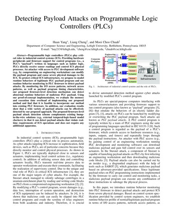
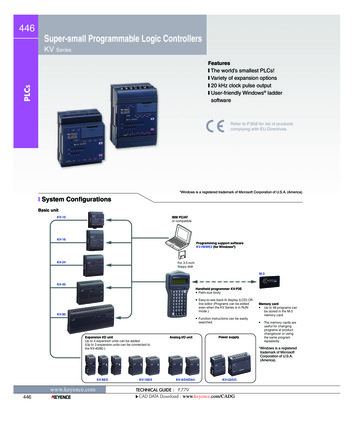
446Super-small Programmable Logic ControllersKV SeriesPLCsFeaturesy The world’s smallest PLCs!y Variety of expansion optionsy 20 kHz clock pulse outputy User-friendly Windows laddersoftwareRefer to P.858 for list of productscomplying with EU Directives.*Windows is a registered trademark of Microsoft Corporation of U.S.A. (America).y System ConfigurationsBasic unitKV-10IBM PC/ATor compatibleKV-16Programming support softwareKV-H6WE2 (for Windows )KV-24For 3.5 inchfloppy diskM-3KV-40Handheld programmer KV-P3E Palm-size body Easy-to-see back-lit display (LCD) Offline editor (Programs can be editedeven when the KV Series is in RUNmode.)KV-80 Function instructions can be easilysearched.Expansion I/O unitUp to 4 expansion units can be added.(Up to 3 expansion units can be connected tothe KV-40/80.)KV-8EXwww.keyence.com446KV-16EXAnalog I/O unitPower supplyMemory card Up to 48 programs canbe stored in the M-3memory card. The memory cards areuseful for changingprograms at productchangeover or usingthe same programrepeatedly.* Windows is a registeredtrademark of MicrosoftCorporation of U.S.A.(America).KV-AD4/DA4KV-U2/U3TECHNICAL GUIDE : P.779CAD DATA Download : www.keyence.com/CADG
Super-small Programmable Logic ControllersKV447y DescriptionConvenient analog timerThe KV-10 (with 10 I/Os) is about the same size as threegeneral-purpose relays. The KV-80 (with 80 I/Os) is as smallas a VHS videotape. KV Series PLCs require little space on acontrol panel.KV-10Useful during startup, the analog timer trimmer enables theadjustment of the values for timers and counters, in real time,based on actual operating conditions, with a range from 0 to249. There are 2 analog timers in the KV-80, KV-40, andKV-24, and 1 in the KV-16 and KV-10.PLCsSmallest PLCs in the world20 kHz clock pulse output (KV-80)The 20 kHz clock pulse output enables positioning at varyingspeeds. The KV Series is useful as a pulse generator forstepping motors.(The KV-10/16/24/40 has a maximum clock frequency of2 kHz.)The KV-10 can be mounted in two-thirds thespace required by conventional 10 I/O PLCs.Several expansion options available toincrease the number of I/OsExample of trapezoidal control(ramp up/down control)20 kHz max. (frequency)1500Up to 4 expansion units can be added.500Basic unitExpansion I/O unitsI/O 4 each8 inputs16 inputs8 outputsTimeSpeed- Constant Speedupspeeddowntimetimetime16 outputsBuilt-in DisplayVisual V-16EXKV-300KV-16EYT/RKVWith the KV Series, it’s easy to expand the number of I/Os. Toachieve the input/output ratio that suits your needs, KV-16E orKV-8E expansion units can be added in any combination of 3to the KV-80 or KV-40. Any combination of 4 expansions unitscan be added to the other models.Analog I/O units with 12-bit resolutionOther useful featuresThe KV-DA4 (D/A connector) and KV-AD4 (A/D converter) with4 channel I/O are available. Built-in 1 ms timer Memory capacity of up to 3000 steps(500 steps: KV-10/16) Serial communication function Relay replacement is possible. (KV-80R, KV-16EYR) Programs are stored in EEPROM, eliminating the need forbackup battery.Support software for Windows The new Ladder Builder support software enables a programto be debugged on a PC screen without connecting a PLC orother device.* Windows is a registered trademark of Microsoft Corporation of U.S.A.(America).Interrupts and countersThe interrupt input instruction receives pulse signals as shortas 25 µs regardless of the program cycle time, thus allowingreal time processing.The KV Series also provides two 10 kHz counters that aresuitable for counting pulses with a high frequency.TECHNICAL GUIDE : P.779CAD DATA Download : www.keyence.com/CADGwww.keyence.com447
448y Input/Output CircuitsInput circuitBJT photocoupler Applicable to all KV models. *Values in ( ) used only for terminalsconnected to relays other than 0000through 0005. Input from both NPN [( ) connectedto COM] and PNP [(-) connected toCOM] transistors are applicable.XKLCompactKV-300KVBJTphotocouplerCOM Internal circuitAnalog-I/OL Applicable only to KV-80T (terminalsother than 0500), KV-10T, KV-8ET,KV-8EYT, and KV-16EYT A separate power supply is requiredfor the load.Output circuit (terminal 0500 on KV-80T only)LCOM Applicable only to the KV-80R,KV-40R, KV-24R, KV-16R, KV-10R,KV-8ER, KV-8EYR, and KV-16EYR. A separate power supply is requiredfor the load.OUTInternal circuitBuilt-in DisplayL Relay is suppliedwith 24 VDC byinternal circuit.Output circuit (MOS-FET)Visual KVCOMInternal circuit OUTInsulation circuit560 Ω*(510 Ω)Internal circuitPLCs24 VDCCOMOutput circuit (BJT)OUT3 kΩ*(4.3 kΩ)Internal circuitINOutput circuit (relay contact) MOS-FET photocouplerOUTLCOM A separate power supply is requiredfor the load. Applicable only to the KV-40T, KV-24T,and KV-16T. A separate power supply is requiredfor the load.y SoftwareThe Ladder Builder for KV creates sequence programs in Windows KV-H6WE2User-friendly operation and high-level programming capabilities make the Ladder Builder for KV [KV-H6WE2] ideal for beginnersand experienced programmers alike.* Windows is a registered trademark of Microsoft Corporation of U.S.A.(America).y EditorEasy editing using Windows functionsMulti-file editingMultiple files can be edited simultaneously on theLadder Builder for KV. You can freely cut and pastefrom one file to another.www.keyence.com448TECHNICAL GUIDE : P.779CAD DATA Download : www.keyence.com/CADG
Super-small Programmable Logic ControllersInstruction selection windowUNDO functionThe user-friendly design allows data entry from a keyboard ora mouse. You can select and specify a device or commandfrom a list provided by device type.This ensures error-free entry of target symbols. For fastprogramming, you can also enter the symbol directly by typingthe command from the keyboard.The Ladder Builder for KV enables efficient editing. If youaccidentally delete an instruction, you can undo the actionsimply by clicking the “Undo” button. “Redo” button cancels“Undo”.KV449PLCsAuto-save functionUsage listWhen creating Ladder diagrams, it can be difficult to keeptrack of addresses already used. The usage list displayswhich ones are used/available.The Ladder Builder for KV automatically backs up yourprogram at predetermined intervals. This protects your datafrom being lost due to PC power loss or system crash.Built-in DisplayVisual KVAnalog-I/OKLCompactKV-300y SimulatorKVQuick debugging without a PLCForward/reverse single step executionEven without a PLC connected, the Ladder Builder for KV cansimulate program execution. The execution can be checkedwithout transferring the program to the PLC. By providing asingle-step execution function (forward or reverse) in additionto a regular scan execution function, debugging efficiency isincreased.You can easily find a problem in complex operations bychecking the operation process one step at a time.Ladder Simulator enables direct checkingof the ladder diagram executionBy clicking an element in the ladder diagram, the simulatorscreen quickly appears, allowing element setting/resetting.Monitors All functionTimers, counters and data memories can be checkedsimultaneously in multiple windows. For effective debugging,you can check devices at one time, which don’t directlyappear in the ladder diagram.Registration MonitorThe Ladder Builder for KV can display multiple timing chartsof any devices simultaneously. This enables convenientchecking of all element on/off timing.y MonitorReal time monitoring without stopping the machineLadder diagram and element on/off stands can be monitored real time.Timing charts can be monitored simultaneously.TECHNICAL GUIDE : P.779CAD DATA Download : www.keyence.com/CADGwww.keyence.com449
450y SpecificationsInput/Output specificationsPLCsTypeModelNo. of inputsCommon inputInput ratingNo. of outputsCommon outputType of outputKV-10RKV-10T641RelayBJTRated loadTypeModelNo. of inputsCommon inputInput ratingNo. of outputsCommon outputType of outputRated loadKV-8ERRelayBasic unitKV-24RKV-24TKV-40RKV-40T101624124 VDC, Current consumption 7 mA (Input 000 to 005) 5 mA: TRelay: 250 VAC/30 VDC, 2 A, peak load current 5 A, Transistor: 30 VDC, 0.3 AMOS-FET: 30 VDC, 0.6 A (Output 0500), 30 VDC, 0.5 A (Others) peak load current 1 AKV-16RKV-16TExpansion ��16—12—4—24 VDC, Current consumption 7 mA (Input 000 to 005) 5 mA: JTRelay: 250 VAC/30 VDC, 2 A, peak load current 5 A, Transistor: 30 VDC, 0.3 AMOS-FET: 30 VDC, 0.6 A (Output 0500), 30 VDC, 0.5 A (Others) peak load current 1 AKV-8ETBuilt-in DisplayVisual KVAnalog-I/OKLCompactKV-300Power supply unit specificationsModelOperation systemPower supply voltageOutput voltageOutput currentWeight (brackets not included)KV-U2KV-U3Switching type100 to 240 VAC (50/60 Hz) 10%24 VDC 10% (Ripple: 240 m Vp-p max.)0.8 AApprox. 170 g1.4 AApprox. 300 gKVAnalog I/O specifications (Input: KV-AD4, Output: KV-DA4)TypeAnalog I/O rangeInput impedanceOutput impedanceNumber of I/OResolutionwww.keyence.com450Voltage-10 to 10 V1 MΩ0.5 Ω min.Current4 to 20 mA300 Ω—4 channels of inputs or outputs5 mV (1/4000)TECHNICAL GUIDE : P.779CAD DATA Download : www.keyence.com/CADG4 µA (1/4000)KV-80RKV-80T483214RelayBJT
Super-small Programmable Logic ControllersKV451General specifications (R and T in model names indicate relay output and transistor output)Timer/CounterHigh-speed counterHigh-speed counter comparatorDirect clock pulseMemory backupSupply voltageMaximum current consumptionAmbient temperatureRelative humidityWithstand voltageWeightKV-10 (R/T)KV-16 (R/T)KV-24 (R/T)KV-40 (R/T)Ladder diagram and expanded ladder diagramBasic: 16, application: 34, arithmetic:26, interrupt: 41.0 µs min., 1.92 µs averageKV-80 (R/T)1.4 µs min., 3.12 µs average500 steps/program3000 steps/program6 inputs (70 max.)10 inputs (74 max.)16 inputs (80 max.)4 outputs (68 max.)6 outpus (70 max.)8 outputs (72 max.)748024 inputs (72 max.)48 inputs (80 max.)16 outputs (64 max.)32 outputs (80 max.)88PLCsModelProgramming languageNumber of instructionsExecution time(basic I/O instructions)Avg. number of stepsInput (Maximum extendable numberof inputs)Output (Maximum extendablenumber of outputs)Maximum extendable number of I/OsInternal utility relays(with latching function)Special utility relaysData memory (16 bits)Temporary memory (16 bits)1281608001601,000 words2,000 words32 wordsA total of 64 timers, up, and up-downcounters are provided:0.1-s timer (0 to 6553.5 s)0.01-s timer (0 to 655.35 s)1-ms timer (0 to 65.535 s)1 analog timer(0 to 24.9 s, 0 to 2.49 s, or 0 to 0.249 s)A total of 120 timers, up, and up-down counters are provided:0.1-s timer (0 to 6553.5 s)0.01-s timer (0 to 655.35 s)1-ms timer (0 to 65.535 s)2 analog timers (two of 0 to 24.9 s, 0 to 2.49 s, or 0 to 0.249 s)2 auto-reset up-counters (max. input response frequency: 10 kHz)42 channels, 2 kHz max. (output from 0500), 1.5 kHz max. (output from 0501)2 channels, 20 kHz max.(output from 0500),1.5 kHz max.(output from 0501)Program memory: EEPROM, programs retained for 10 years min., rewritable 50,000 times min.Data memory: data retained for 2 months min. by capacitors (at 25 C (77 F))24 VDC 10% to -20%KV-10R: 75 mAKV-16R: 105 mAKV-24R: 130 mAKV-40R: 220 mAKV-80R: 400 mAKV-10T: 65 mAKV-16T: 70 mAKV-24T: 75 mAKV-40T: 115 mAKV-80T: 300 mA0 to 50 C (32 to 122 F), No condensation35 to 85%, No condensation1500 VAC applied between power terminal and I/O terminal, and between terminals and housing (1 min.)KV-10R: approx. 130 gKV-16R: approx. 200 gKV-24R: approx. 250 gKV-40R: approx. 340 gKV-80R: approx. 600 gKV-10T: approx. 120 gKV-16T: approx. 180 gKV-24T: approx. 220 gKV-40T: approx. 270 gKV-80T: approx. 500 gTECHNICAL GUIDE : P.779CAD DATA Download : www.keyence.com/CADGBuilt-in DisplayVisual KVAnalog-I/OKLCompactKV-300KVwww.keyence.com451
452y InstructionsBasic instructionsInstructionLOADLDBConnects N.C. contact to bus.ANDConnects N.O. contact in series with previous contact.ANBConnects N.C. contact in series with previous contact.ORConnects N.O. contact in parallel with previous contact.ORBConnects N.C. contact in parallel with previous contact.AND LOADANLConnects in series blocks made of one or more contacts.OR LOADORLConnects in parallel blocks made of one or more contacts.OUTOutputs input ON/OFF status to R coil.OUBOutputs inverted input ON/OFF status to R coil.SETForces R ON and holds this status when input is ON.PLCsAND BAROROR BAROUTOUT BARVisual KVKLCompactKV-300KVFunctionConnects N.O. contact to bus.ANDAnalog-I/OMnemonicLDLOAD BARBuilt-in ET(SET)RESET(RES)RESForces R/T/C OFF when input is ON.0.1-s TIMER#dddddT xxxTMR16-bit on-delay T that counts down in 0.1-s decrements.TMH (FNC49)16-bit on-delay T that counts down in 0.01-s decrements.TMS (FNC51)16-bit on-delay T that counts down in 1-ms decrements.0.01-s TIMER1-ms TIMERCOUNTERnnnn#dddddT xxxH#dddddT xxxS#dddddC xxxnnnnCSets 16-bit up-counter.Application instructionsInstructionUP-DOWN COUNTERMnemonicFunctionUDC (FNC52)Sets a 16-bit up-down counter.DIFFERENTIATE UPnnnnDIFUDIFU (FNC10)Turns ON R for 1 scan time at rising edge of input.DIFFERENTIATE DOWNnnnnDIFDDIFD (FNC09)Turns ON R for 1 scan time at falling edge of input.KEEP (FNC22)Turns ON R and holds this status when SET input is ON. Turns OFF R whenRESET input is ON.KEEPKEEPSETRESSHIFTUP nnnnDWRES mmmmHIGH SPEEDMASTER CONTROLMASTER CONTROL RESETMEMORY SWITCHSTAGEwww.keyence.com452SymbolUDC xxxUP #dddddDWRESnnnnSFTHSPnnnnMCMCRMEMSWnnnnSTGSFT (FNC39)Sets shift register.HSP (FNC18)Reduces input relay time constant to 25 µs for higher input response.MC (FNC24)Selects ON/OFF status of R coils, Ts, or Cs.MCR (FNC25)Represents end of MC.MEMSW (FNC26)Sets memory switches.STG (FNC 44)Executes instructions between STG & JMP when R (operand) is ON.TECHNICAL GUIDE : P.779CAD DATA Download : www.keyence.com/CADG
Super-small Programmable Logic ControllersKV453Application instructionsJUMPnnnnJMPJMP (FNC 21)Turns current stage OFF and next stage ON when input is ON.END STAGEENDSENDS (FNC 14)Turns current stage OFF when input is ON.NOPNOP (FNC30)ENDHEND HIApplication instructionsInstructionSTEPSTEP ENDINTERVAL TIMER8 BIT COUNTER8 BIT COUNTER COMPARATORSUBROUTINE CALLSUBROUTINE ENTRYSUBROUTINE RETURNREPEAT STARTREPEAT END16 KEY INPUTWAIT ONWAIT OFFWAIT UP EDGEWAIT DOWN EDGECONNECTPUSHREADPOPIndicates end of each routine of program.ENDHIndicates end of entire program.Arithmetic EXTHKEYW-ONW-OFFW-UEW-DECONMPSMRDMPPInterrupt instructionsINTERRUPT DISABLEDINTERRUPT ENABLEDINTERRUPTRETURN INTERRUPTENDPLCsENDENDPerforms no operation.DIEIINTRETIDATA MEMORY WRITETRIMMER SETINGLOAD ASTORE ACOMPAREADDSUBTRACTMULTIPLYDIVIDEAND AOR AEXCULSIVE OR ASHIFT RIGHT ASHIFT LEFT AROTATE RIGHT AROTATE LEFT ACOMPLEMENTINCREMENT MEMORYDECREMENT MEMORYMULTIPLEXERDEMULTIPLEXERTRANSFER BCDTRANSFER BINASCII CONVERTREVERSE ASCII CONVERTSQUARE ARLACOMINCDECMPXDMXTBCDTBINASCRASCROOTBuilt-in DisplayVisual KVAnalog-I/OKLCompactKV-300KV* Differentiation instructions can be used for all arithmetic instructions other than DATAMEMORY WRITE.TECHNICAL GUIDE : P.779CAD DATA Download : www.keyence.com/CADGwww.keyence.com453
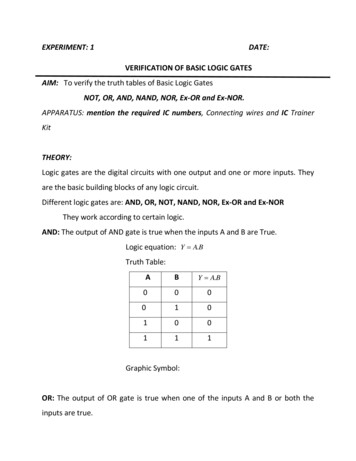
454y DimensionsUnit: mm inchBasic unitsKV-80R/TKV-40R/TPLCsø0.20"4 x ø5 mounting holeø0.20"2 x ø5 mounting 33"431.69"11190 4.37"3.54"Built-in DisplayVisual KVAnalog-I/OKV-24R/TKV-16R/TKLø0.20"2 x ø5 mounting holeø0.20"2 x ø5 mounting 93.90"90 1113.54" 31.69"KV-10R/Tø0.20"2 x ø5 mounting w.keyence.com454702.76"913.58"TECHNICAL GUIDE : P.779CAD DATA Download : www.keyence.com/CADG90 1113.54" 4.37"
Super-small Programmable Logic ControllersKV455Unit: mm inchExpansion 20"2 x ø5 mounting holeø0.20"2 x ø5 mounting hole35.41.39"1.22"311.54"39652.60"431.69"993.90"90 1113.54" .75"431.70"381.50"Handheld programmerPower suppliesKV-P3EKV-U2Built-in Display3.54"90Visual KVø0.20"2 x ø5 mounting .54"KV1.38"35391.54"KV-U3ø0.20"2 x ø5 mounting hole993.90"35.41.39"1.97"503.07"781104.33"11190 4.37"3.54"1.54"39431.70"TECHNICAL GUIDE : P.779CAD DATA Download : www.keyence.com/CADGwww.keyence.com455
Super-small Programmable Logic Controllers KV General specifications (R and T in model names indicate relay output and transistor output) Model KV-10(R/T) KV-16(R/T) KV-24(R/T) KV-40(R/T) KV-80(R/T) Programming language Ladder diagram and expanded ladder diagram Number of instruction