Transcription
MechatronicsProgrammable Logic ControllerBasic ProgrammingCourseware Sample52281-F0
Order no.:52281-10First EditionRevision level: 08/2015By the staff of Festo Didactic Festo Didactic Ltée/Ltd, Quebec, Canada 2015Internet: www.festo-didactic.come-mail: did@de.festo.comPrinted in CanadaAll rights reservedISBN 978-2-89747-462-1 (Printed version)ISBN 978-2-89747-464-5 (CD-ROM)Legal Deposit – Bibliothèque et Archives nationales du Québec, 2015Legal Deposit – Library and Archives Canada, 2015The purchaser shall receive a single right of use which is non-exclusive, non-time-limited and limitedgeographically to use at the purchaser's site/location as follows.The purchaser shall be entitled to use the work to train his/her staff at the purchaser's site/location andshall also be entitled to use parts of the copyright material as the basis for the production of his/her owntraining documentation for the training of his/her staff at the purchaser's site/location withacknowledgement of source and to make copies for this purpose. In the case of schools/technicalcolleges, training centers, and universities, the right of use shall also include use by school and collegestudents and trainees at the purchaser's site/location for teaching purposes.The right of use shall in all cases exclude the right to publish the copyright material or to make thisavailable for use on intranet, Internet and LMS platforms and databases such as Moodle, which allowaccess by a wide variety of users, including those outside of the purchaser's site/location.Entitlement to other rights relating to reproductions, copies, adaptations, translations, microfilming andtransfer to and storage and processing in electronic systems, no matter whether in whole or in part, shallrequire the prior consent of Festo Didactic GmbH & Co. KG.Information in this document is subject to change without notice and does not represent a commitment onthe part of Festo Didactic. The Festo materials described in this document are furnished under a licenseagreement or a nondisclosure agreement.Festo Didactic recognizes product names as trademarks or registered trademarks of their respectiveholders.All other trademarks are the property of their respective owners. Other trademarks and trade names maybe used in this document to refer to either the entity claiming the marks and names or their products.Festo Didactic disclaims any proprietary interest in trademarks and trade names other than its own.
Safety and Common SymbolsThe following safety and common symbols may be used in this manual and onthe equipment:SymbolDescriptionDANGER indicates a hazard with a high level of risk which, if notavoided, will result in death or serious injury.WARNING indicates a hazard with a medium level of risk which,if not avoided, could result in death or serious injury.CAUTION indicates a hazard with a low level of risk which, if notavoided, could result in minor or moderate injury.CAUTION used without the Caution, risk of danger sign ,indicates a hazard with a potentially hazardous situation which,if not avoided, may result in property damage.Caution, risk of electric shockCaution, hot surfaceCaution, risk of dangerCaution, lifting hazardCaution, hand entanglement hazardNotice, non-ionizing radiationDirect currentAlternating currentBoth direct and alternating currentThree-phase alternating currentEarth (ground) terminal Festo Didactic 52281-10III
Safety and Common SymbolsSymbolDescriptionProtective conductor terminalFrame or chassis terminalEquipotentialityOn (supply)Off (supply)Equipment protected throughout by double insulation orreinforced insulationIn position of a bi-stable push controlOut position of a bi-stable push controlIV Festo Didactic 52281-10
Table of ContentsPreface . XIAbout This Manual . XIIITo the Instructor . XVExercise 1Familiarization with the PLC Trainer and RSLogix Micro . 1DISCUSSION. 1Introduction . 1PLC Hardware . 3Power Supply section . 3Input section . 3Output section . 4Central Processing Unit . 4Memory section (Input and Output) . 4Status Indicators . 6The PLC Trainer . 7The RSLogix Micro Software . 10Running RSLogix Micro . 10Projects . 12Configuring System Communications . 14Editing System Preferences . 15PROCEDURE . 16Running RSLogix Micro. 16Editing the Project Files Search Path. 16Configuring System Communications . 16Creating a New Project . 17The Project Tree . 17The Instruction Toolbar . 18The Online Section . 18Saving a Project to a File . 18Exercise 2Online Operations and Monitoring I/O Data Files. 21DISCUSSION. 21Data file organization . 21Input and output data files . 22PLC input and output interfaces . 24PLC input interface . 24PLC output interface . 25PLC modes of operation. 26PROCEDURE . 28Set up and connections . 28Downloading a ladder program to the PLC processor . 31Input data file . 32Output data file . 35Word level. 37Clearing the PLC Memory . 41 Festo Didactic 52281-10V
Table of ContentsExercise 3Relay Instructions Part 1 . 43DISCUSSION . 43Introduction . 43Input instructions . 43Examine if Closed (XIC) . 43Examine if Open (XIO) . 44Output instruction . 45Output Energize (OTE) . 46PROCEDURE . 47Set up and connections . 47Ladder program using XIC and OTE instructionscontrolled by an NO push button . 49Ladder program using XIC, XIO, and OTE instructionscontrolled by NO push buttons . 51Ladder program using XIC, XIO, and OTE instructionscontrolled by NC push buttons . 54Developing a program to control an output using two pushbuttons . 56Developing a program to control an output using fourpush buttons . 57Series (AND) and parallel (OR) logics . 58Developing a program to control three outputs using onepush button . 60Developing a program to control three outputs using twopush buttons . 61Exercise 4Relay Instructions Part II . 65DISCUSSION . 65Introduction . 65Latching instructions . 65Output Latch (OTL) . 65Output Unlatch (OTU) . 66Latching instruction operation . 66PROCEDURE . 67Set up and connections . 67Ladder program using latching instructions . 67Developing a program acting as a single Start/Stopstation using latching instructions. 70Developing a program acting as a multiple Start/Stopstation using latching instructions. 71Developing a program acting as a Forward/Reversecontrol circuit using holding contacts . 72Developing a program acting as a Forward/Reversecontrol circuit using latching instructions . 74VI Festo Didactic 52281-10
Table of ContentsExercise 5Timer Instructions. 77DISCUSSION. 77Introduction . 77Timer instruction parameters. 78Timer. 78Time base . 78Preset . 78Accumulator (Accum). 78Timer status bits . 79Timer Enable (EN) . 80Timer Timing (TT) . 80Done (DN) . 80Timer instructions . 80Timer-on-Delay (TON) . 80Timer-off-Delay (TOF). 81Retentive Timer-on-Delay (RTO) . 81Reset (RES) instruction . 82PROCEDURE . 83Set up and connections . 83The Timer-on-Delay (TON) instruction . 83The Timer-off-Delay (TOF) instruction . 87The Retentive Timer-on-Delay (RTO) instruction . 89Developing a flasher circuit using two timer instructions . 91Developing a flasher circuit using three timer instructions . 92Exercise 6Counter Instructions. 97DISCUSSION. 97Introduction . 97Counter instructions parameters . 97Address. 97Preset . 98Accumulator (Accum). 98Counter status bits . 98Count Up Enable (CU) . 99Count Down Enable (CD) . 99Done (DN) . 99Overflow (OV) . 100Underflow (UN) . 100Counter instructions . 100Count Up (CTU) . 100Count Down (CTD) . 100Reset (RES) instruction . 101PROCEDURE . 101Set up and connections . 101The Count Up (CTU) instruction . 102The Count Down (CTD) instruction . 107 Festo Didactic 52281-10VII
Table of ContentsExercise 7Comparison Instructions . 113DISCUSSION . 113Introduction . 113Comparison instruction parameters . 114Source A .114Source B .114Low Limit .114High Limit .114Test .114Comparison instructions . 114Equal (EQU) .114Not Equal (NEQ) .115Less Than (LES) .115Less Than or Equal (LEQ) .115Greater Than (GRT) .115Greater Than or Equal (GEQ) .116Limit (LIM) .116Using comparison instructions to perform sequentialcontrol . 116PROCEDURE . 117Set up and connections . 117The Equal (EQU) instruction . 117The Not Equal (NEQ) instruction . 121The Greater Than (GRT) instruction . 124The Greater Than or Equal (GEQ) instruction . 127The Less Than (LES) instruction . 129The Less Than or Equal (LEQ) instruction . 131The Limit (LIM) instruction . 133Counter-driven comparison instructions . 135Timer-driven comparison instructions . 137Developing a traffic light simulation program usingcomparison instructions. 139Exercise 8Move Instructions . 143DISCUSSION . 143Introduction . 143Move instruction parameters . 143Source .143Destination .144Mask .144Move instructions . 144Move (MOV) .144Move with Mask (MVM) .144VIII Festo Didactic 52281-10
Table of ContentsPROCEDURE . 145Set up and connections . 145The Move (MOV) instruction using a constant as sourcevalue . 146The Move (MOV) instruction using a value from anaddressed word as source value . 149Developing a program using move instructions to controloutputs . 152Developing a program using comparison and moveinstructions to control six outputs . 157Developing a traffic light simulation program using moveinstructions . 159The Move with Mask (MVM) instruction . 161Exercise 9Sequencer Instructions . 167DISCUSSION. 167Introduction . 167Sequencer instruction parameters . 168File . 168Mask . 168Source . 168Destination . 168Control . 168Length of the sequencer file . 168Position . 169Sequencer status bits . 169Enable (EN) . 169Done (DN) . 169Error (ER) . 169Found (FD) . 170Sequencer instructions . 170Sequencer Output (SQO) . 170Sequencer Compare (SQC) . 172Reset instruction . 174PROCEDURE . 174Set up and connections . 174The Sequencer Output (SQO) instruction . 174The Sequencer Compare (SQC) instruction . 179Developing a program using SQO and TON instructions . 183Appendix A Equipment Utilization Chart . 187Appendix B Glossary of New Terms . 189Appendix C Conversion Table . 191 Festo Didactic 52281-10IX
Table of ContentsAppendix D Boolean Algebra and Digital Logic . 193Appendix E PLC Trainer, Model 3240-A . 197Appendix F PLC Trainer, Model 3240-D . 205Appendix G PLC Trainer, Model 3240-3 . 213Index. 217Acronyms . 219Bibliography . 221X Festo Didactic 52281-10
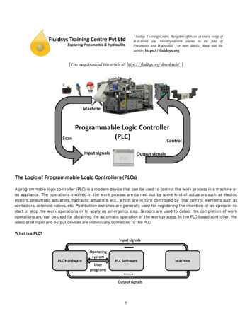
PrefaceProgrammable logic controllers (PLCs) are at the center of a multitude ofautomated systems. Some industries that benefit from these systems includemanufacturing plants, breweries, wastewater treatment plants, mining facilities,and automotive assembly plants.This manual, Programmable Logic Controller - Basic Programming, introducesstudents to PLC ladder program editing using the most common PLCinstructions: relay instructions, timer instructions, counter instructions,comparison instructions, move instructions, and sequencer instructions. Thesoftware used to edit the ladder programs is the RSLogix Micro software fromRockwell. The edited programs are downloaded to an Allen-Bradley PLC andtested by activating PLC inputs and monitoring the PLC outputs status indicators.We invite readers of this manual to send us their tips, feedback, andsuggestions for improving the book.Please send these to did@de.festo.com.The authors and Festo Didactic look forward to your comments. Festo Didactic 52281-10XI
About This ManualManual objectivesWhen you have completed this manual, you will be able to navigate through theRSLogix Micro software from Rockwell and use the online resources. You willknow how to develop ladder programs and use the most common PLCinstructions.Utilization of this manual with various PLC trainersThis manual was written specifically for the PLC Trainer, Model 3240-4, whichuses an Allen-Bradley MicroLogix 1200 controller.However, the manual can also be used with the PLC Trainer, Model 3240-A, thatuses an Allen-Bradley MicroLogix 1100 controller, the PLC Trainer,Model 3240-D, that uses an Allen-Bradley MicroLogix 1100 controller, or thePLC Trainer, Model 3240-3, that uses an Allen-Bradley MicroLogix 1500controller. If you are using the PLC Trainer, Model 3240-A, skip the DISCUSSIONsection entitled The PLC Trainer of Exercise 1, and refer to Appendix Einstead for a description of Model 3240-A. If you are using the PLC Trainer, Model 3240-D, skip the DISCUSSIONsection entitled The PLC Trainer of Exercise 1, and refer to Appendix Finstead for a description of Model 3240-D. If you are using the PLC Trainer, Model 3240-3, skip the DISCUSSIONsection entitled The PLC Trainer of Exercise 1, and refer to Appendix Ginstead for a description of Model 3240-3.Safety considerationsSafety symbols that may be used in this manual and on the equipment are listedin the Safety Symbols table at the beginning of the manual.Safety procedures related to the tasks that you will be asked to perform areindicated in each exercise.Make sure that you are wearing appropriate protective equipment whenperforming the tasks. You should never perform a task if you have any reason tothink that a manipulation could be dangerous for you or your teammates.Reference materialThe Programmable Logic Controllers from Frank D. Petruzella (McGraw-Hill Ed.,2010) is a reference to complement and expand on PLCs.The User's manuals provided with the Allen-Bradley PLC is also anotherreference. Festo Didactic 52281-10XIII
About This ManualPrerequisiteAs a prerequisite to this course, you should have a basic understanding ofelectricity. It is assumed that you have a general understanding of the followingconcepts: DC and ac voltage, current, power Series and parallel circuits NO and NC contacts Push buttons, toggle switches, relaysSystems of unitsUnits are expressed using the International System of Units (SI) followed by theunits expressed in the U.S. customary system of units (between parentheses).XIV Festo Didactic 52281-10
To the InstructorYou will find in this Instructor Guide all the elements included in the StudentManual together with the answers to all questions, results of measurements,graphs, explanations, suggestions, and, in some cases, instructions to help youguide the students through their learning process. All the information that appliesto you is placed between markers and appears in red.Accuracy of measurementsThe numerical results of the hands-on exercises may differ from one student toanother. For this reason, the results and answers given in this manual should beconsidered as a guide. Students who correctly performed the exercises shouldexpect to demonstrate the principles involved and make observations andmeasurements similar to those given as answers.Software requirementsIn order for students to be able to perform the exercises in this manual, theRSLogix Micro, and the RSLinx Classic software must have been previouslyinstalled on the student's computer, according to the manufacturer's instructions.Configuration of RSLinx ClassicIn RSLinx Classic, configure the driver for an AB DF1 device (communicationdevice for a Micrologix PLC) at station 0. Select the serial or com port of thecomputer to which the Micrologix PLC will be connected through the serial1761-CBL cable. Set the baud rate to 19 200. The recommended protocol for theMicrologix PLCs is full-duplex.aIf the PLC used on your trainer is the Allen-Bradley Micrologix 1100controller , and you are using an Ethernet communication link, configure thedriver for an Ethernet/IP device. The system must be configured via theBOOTP (bookstrap protocol). (Refer to the section “Connecting to network viaEthernet Interface” of the Allen-Bradley User Manual.)You are now ready to use RSLogix Micro to program and control the PLC. Tostart RSLogix Micro, select the corresponding command in the RockwellSoftware program group. Festo Didactic 52281-10XV
Sample ExerciseExtracted fromthe Student Manualand the Instructor Guide
Exercise5Timer InstructionsEXERCISE OBJECTIVEWhen you have completed this exercise, you will be familiar with the timerinstructions and their use in PLC programs. Throughout this exercise, you willdevelop programs using these instructions to control various operations.DISCUSSION OUTLINEThe Discussion of this exercise covers the following points: IntroductionTimer instruction parameters Timer status bits Timer instructionsTimer. Time base. Preset. Accumulator (Accum). DISCUSSIONTimer Enable (EN). Timer Timing (TT). Done (DN).Timer-on-Delay (TON). Timer-off-Delay (TOF). Retentive Timer-on-Delay(RTO).Reset (RES) instructionIntroductionThe Timer instructions are frequently used in programs to control processesbased on time constraints to achieve a specific operation. Such instances maybe one of the following: To allow a specific amount of time to occur before an operation To allow a specific amount of time to occur after an operation To allow an operation to occur for a specific amount of timeIn order to correctly use these instructions, we must investigate their operationand use in ladder logic programs.Timer instruction parametersThe timer instructions have the following parameters: Timer, Time base, Preset,and Accumulator. These parameters must be programmed when entering a timerinstruction.TimerThe Timer parameter is the address of the timer file; it is located in the timer datafile. The default timer file is T4 and it is created automatically at the time theprogram is developed. Figure 54 show
Programmable logic controllers (PLCs) are at the center of a multitude of automated systems. Some industries that benefit from these systems include manufacturing plants, breweries, wastewater treatment plants, mining facilities, and automotive assembly plants. This manual, Programmable Logic Co
