Transcription
Programmable Logic Controllers:Programming Methodsand ApplicationsbyJohn R. HackworthandFrederick D. Hackworth, Jr.
Table of ContentsChapter 1 - Ladder Diagram FundamentalsChapter 2 - The Programmable Logic ControllerChapter 3 - Fundamental PLC ProgrammingChapter 4 - Advanced Programming TechniquesChapter 5 - Mnemonic Programming CodeChapter 6 - Wiring TechniquesChapter 7 - Analog I/OChapter 8 - Discrete Position SensorsChapter 9 - Encoders, Transducers, and Advanced SensorsChapter 10 - Closed Loop and PID ControlChapter 11 - Motor ControlsChapter 12 - System Integrity and Safety
PrefaceMost textbooks related to programmable controllers start with the basics ofladder logic, Boolean algebra, contacts, coils and all the other aspects of learning toprogram PLCs. However, once they get more deeply into the subject, they generallynarrow the field of view to one particular manufacturer's unit (usually one of the morepopular brands and models), and concentrate on programming that device with it'scapabilities and peculiarities. This is worthwhile if the desire is to learn to program thatunit. However, after finishing the PLC course, the student will most likely be employedin a position designing, programming, and maintaining systems using PLCs of anotherbrand or model, or even more likely, many machines with many different brands andmodels of PLC. It seems to the authors that it would be more advantageous toapproach the study of PLCs using a general language that provides a thoroughknowledge of programming concepts that can be adapted to all controllers. Thislanguage would be based on a collection of different manufacturer types with generallythe same programming technique and capability. Although it would be impossible toteach one programming language and technique that would be applicable to each andevery programmable controller on the market, the student can be given a thoroughinsight into programming methods with this general approach which will allow him or herto easily adapt to any PLC encountered.Therefore, the goal of this text is to help the student develop a good generalworking knowledge of programmable controllers with concentration on relay ladder logictechniques and how the PLC is connected to external components in an operatingcontrol system. In the course of this work, the student will be presented with real worldprogramming problems that can be solved on any available programmable controller orPLC simulator. Later chapters in this text relate to more advanced subjects that aremore suitable for an advanced course in machine controls. The authors desire thatthis text not only be used to learn programmable logic controllers, but also that this textwill become part of the student’s personal technical reference library.Readers of this text should have a thorough understanding of fundamental acand dc circuits, electronic devices (including thyristors), a knowledge of basic logicgates, flip flops, and Boolean algebra, and college algebra and trigonometry. Althougha knowledge of calculus will enhance the understanding of PID controls, it is notrequired in order to learn how to properly tune a PID.ii
Chapter 1 - Ladder Diagram FundamentalsChapter 1 - Ladder Diagram Fundamentals1-1.ObjectivesUpon completion of this chapter, you will be able to” identify the parts of an electrical machine control diagram including rungs,branches, rails, contacts, and loads.” correctly design and draw a simple electrical machine control diagram.” recognize the difference between an electronic diagram and an electrical machinediagram.” recognize the diagramming symbols for common components such as switches,control transformers, relays, fuses, and time delay relays.” understand the more common machine control terminology.1-2.IntroductionMachine control design is a unique area of engineering that requires the knowledgeof certain specific and unique diagramming techniques called ladder diagramming.Although there are similarities between control diagrams and electronic diagrams, manyof the component symbols and layout formats are different. This chapter provides a studyof the fundamentals of developing, drawing and understanding ladder diagrams. We willbegin with a description of some of the fundamental components used in ladder diagrams.The basic symbols will then be used in a study of boolean logic as applied to relaydiagrams. More complicated circuits will then be discussed.1-3.Basic Components and Their SymbolsWe shall begin with a study of the fundamental components used in electricalmachine controls and their ladder diagram symbols. It is important to understand that thematerial covered in this chapter is by no means a comprehensive coverage of all types ofmachine control components. Instead, we will discuss only the most commonly used ones.Some of the more exotic components will be covered in later chapters.Control TransformersFor safety reasons, machine controls are low voltage components. Because theswitches, lights and other components must be touched by operators and maintenancepersonnel, it is contrary to electrical code in the United States to apply a voltage higher than1-1
Chapter 1 - Ladder Diagram Fundamentals120VAC to the terminals of any operator controls. For example, assume a maintenanceperson is changing a burned-out indicator lamp on a control panel and the lamp is poweredby 480VAC. If the person were to touch any part of the metal bulb base while it is incontact with the socket, the shock could be lethal. However, if the bulb is powered by120VAC or less, the resulting shock would likely be much less severe.In order to make large powerful machines efficient and cost effective and reduce linecurrent, most are powered by high voltages (240VAC, 480VAC, or more). This means theline voltage must be reduced to 120VAC or less for the controls. This is done using acontrol transformer. Figure 1-1 shows the electrical diagram symbol for a controltransformer. The most obvious peculiarity here is that the symbol is rotated 90 with theprimaries on top and secondary on the bottom. As will be seen later, this is done to makeit easier to draw the remainder of the ladder diagram. Notice that the transformer has twoprimary windings. These are usually each rated at 240VAC. By connecting them inparallel, we obtain a 240VAC primary, and by connecting them in series, we have a480VAC primary. The secondary windings are generally rated at 120VAC, 48VAC or24VAC. By offering control transformers with dual primaries, transformer manufacturerscan reduce the number of transformer types in their product line, make their transformersmore versatile, and make them less expensive.H1H3H2X1H4X2Figure 1-1 - Control TransformerFusesControl circuits are always fuse protected. This prevents damage tothe control transformer in the event of a short in the control circuitry. The Figure 1-2 electrical symbol for a fuse is shown in Figure 1-2. The fuse used in controlFusecircuits is generally a slo-blow fuse (i.e. it is generally immune to currenttransients which occur when power is switched on) and must be rated at a current that isless than or equal to the rated secondary current of the control transformer, and it must beconnected in series with the transformer secondary. Most control transformers can bepurchased with a fuse block (fuse holder) for the secondary fuse mounted on thetransformer, as shown in Figure 1-3.1-2
Chapter 1 - Ladder Diagram FundamentalsFigure 1-3 - Control Transformer withSecondary Fuse Holder(Allen Bradley)SwitchesThere are two fundamental uses for switches. First, switches are used for operatorinput to send instructions to the control circuit. Second, switches may be installed on themoving parts of a machine to provide automatic feedback to the control system. There aremany different types of switches, too many to cover in this text. However, with a basicunderstanding of switches, it is easy to understand most of the different types.PushbuttonThe most common switch is the pushbutton. It is also the one that needs the leastdescription because it is widely used in automotive and electronic equipment applications.There are two types of pushbutton, the momentary and maintained. The momentarypushbutton switch is activated when the button is pressed, and deactivated when the buttonis released. The deactivation is done using an internal spring. The maintained pushbuttonactivates when pressed, but remains activated when it is released. Then to deactivate it,it must be pressed a second time. For this reason, this type of switch is sometimes calleda push-push switch. The on/off switches on most desktop computers and laboratoryoscilloscopes are maintained pushbuttons.1-3
Chapter 1 - Ladder Diagram FundamentalsThe contacts on switches can beof two types. These are normally open(N/O) and normally closed (N/C).Whenever a switch is in it’s deactivatedposition, the N/O contacts will be open Figure 1-4 - Momentary Pushbutton Switches(non-conducting) and the N/C contactswill be closed (conducting). Figure 1-4 shows the schematic symbols for a normally openpushbutton (left) and a normally closed pushbutton (center). The symbol on the right ofFigure 1-4 is a single pushbutton with both N/O and N/C contacts. There is no internalelectrical connection between different contact pairs on the same switch. Most industrialswitches can have extra contacts “piggy backed” on the switch, so as many contacts asneeded of either type can be added by the designer.The schematic symbol for the maintained pushbutton is shownin Figure 1-5. Note that it is the symbol for the momentarypushbutton with a “see-saw” mechanism added to hold in the switchactuator until it is pressed a second time. As with the momentaryswitch, the maintained switch can have as many contacts of eithertype as desired.Figure 1-5 Maintained SwitchPushbutton Switch ActuatorsThe actuator of a pushbutton is the part that you depress to activate the switch.These actuators come is several different styles as shown in Figure 1-6, each with aspecific purpose.The switch on the left in Figure 1-6 has a guarded or shrouded actuator. In thiscase the pushbutton is recessed 1/4"-1/2" inside the sleeve and can only be depressed byan object smaller than the sleeve (such as a finger). It provides protection against thebutton being accidentally depressed by the palm of the hand or other object and istherefore used in situations where pressing the switch causes something potentiallydangerous to happen. Guarded pushbuttons are used in applications such as START,RUN, CYCLE, JOG, or RESET operations. For example, the RESET pushbutton on yourcomputer is likely a guarded pushbutton.The switch shown in the center of Figure 1-6 has an actuator that is aligned to beeven with the sleeve. It is called a flush pushbutton. It provides similar protection againstaccidental actuation as the guarded pushbutton; however, since it is not recessed, the levelof protection is not to the extent of the guarded pushbutton. This type of switch actuatorworks better in applications where it is desired to back light the actuator (called a lightedpushbutton).1-4
Chapter 1 - Ladder Diagram FundamentalsThe switch on the right is an extended pushbutton. Obviously, the actuator extendsbeyond the sleeve which makes the button easy to depress by finger, palm of the hand, orany object. It is intended for applications where it is desirable to make the switch asaccessible as possible such as STOP, PAUSE, or BRAKES.Figure 1-6 - Switch ActuatorsThe three types of switch actuators shown in Figure 1-6 are not generally used forapplications that would be required in emergency situations nor for operations that occurhundreds of times per day. For both of these applications, a switch is needed that is themost accessible of all switches. These types are the mushroom head or palm headpushbutton (sometimes called palm switches, for short), and are illustrated in Figure 1-7.Figure 1-7 - Mushroom Head PushbuttonsAlthough these two applications are radically different, the switches look similar. Themushroom head switch shown on the left of Figure 1-7 is a momentary switch that may beused to cause a machine run one cycle of an operation. For safety reasons, they areusually used in pairs, separated by about 24", and wired so that they must both be pressedat the same time in order to cause the desired operation to commence. When arrangedand wired such as this, we create what is called a 2-handed palming operation. By doing1-5
Chapter 1 - Ladder Diagram Fundamentalsso, we know that when the machine is cycled, the operator has both hands on thepushbuttons and not in the machine.The switch on the right of Figure 1-7 is a detent pushbutton (i.e. when pressed in itremains in, and then to return it to its original position, it must be pulled out) and is calledan Emergency Stop, or E-Stop switch. The mushroom head is always red and the switchis used to shutoff power to the controls of a machine when the switch is pressed in. Inorder to restart a machine, the E-Stop switch must be pulled to the out position to applypower to the controls before attempting to run the machine.E-STOPRUNMushroom head switches have specialschematic symbols as shown in Figure 1-8. Notice thatthey are drawn as standard pushbutton switches buthave a curved line on the top of the actuators to indicate Figure 1-8 - Mushroom Switchesthat the actuators have a mushroom head.Selector SwitchesSTOPRUNA selector switch is also known as a rotaryswitch.An automobile ignition switch, and anoscilloscope’s vertical gain and horizontal timebaseswitches are examples of selector switches. SelectorFigure 1-9 - Selectorsswitches use the same symbol as a momentarypushbutton, except a lever is added to the top of the actuator, as shown in Figure 1-9. Theswitch on the left is open when the selector is turned to the left and closed when turned tothe right. The switch on the right side has two sets of contacts. The top contacts areclosed when the switch selector is turned to the left position and open when the selectoris turned to the right. The bottom set of contacts work exactly opposite. There is noelectrical connection between the top and bottom pairs of contacts. In most cases, welabel the selector positions the same as the labeling on the panel where the switch islocated. For the switch on the right in Figure 1-9, the control panel would be labeled withthe STOP position to the left and the RUN position to the right.Limit SwitchesLimit switches are usually not operator accessible.Instead they are activated by moving parts on themachine. They are usually mechanical switches, but canalso be light activated (such as the automatic door Figure 1-10 - Limit Switchesopeners used by stores and supermarkets), or magnetically operated (such as themagnetic switches used on home security systems that sense when a window has beenopened). An example of a mechanically operated limit switch is the switch on the1-6
Chapter 1 - Ladder Diagram Fundamentalsrefrigerator door that turns on the light inside. They are sometimes called cam switchesbecause many are operated by a camming action when a moving part passes by theswitch. The symbols for both types of limit switches are shown in Figure 1-10. The N/Oversion is on the left and the N/C version is on the right. One of the many types of limitswitch is pictured in Figure 1-11.Figure 1-11 - Limit SwitchIndicator LampsAll control panels include indicator lamps. They tell the operatorwhen power is applied to the machine and indicate the present operatingstatus of the machine. Indicators are drawn as a circle with “light rays”extending on the diagonals as shown in Figure 1-12.Figure 1-12 LampAlthough the light bulbs used in indicators are generallyincandescent (white), they are usually covered with colored lenses. The colors are usuallyred, green, or amber, but other colors are also available. Red lamps are reserved forsafety critical indicators (power is on, the machine is running, an access panel is open, orthat a fault has occurred). Green usually indicates safe conditions (power to the motor isoff, brakes are on, etc.). Amber indicates conditions that are important but not dangerous(fluid getting low, machine paused, machine warming up, etc.). Other colors indicateinformation not critical to the safe operation of the machine (time for preventivemaintenance, etc.). Sometimes it is important to attract the operator’s attention with alamp. In these cases, we usually flash the lamp continuously on and off.RelaysEarly electrical control systems were composed of mainly relays and switches.Switches are familiar devices, but relays may not be so familiar. Therefore, before1-7
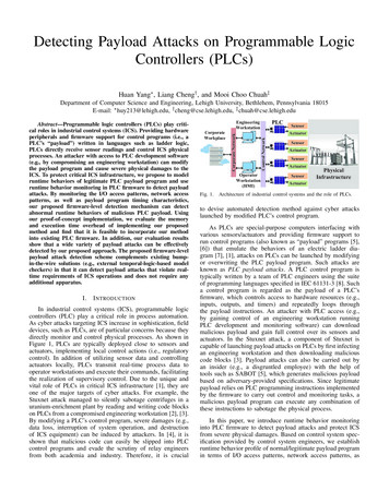
Chapter 1 - Ladder Diagram Fundamentalscontinuing our discussion of machine control ladder diagramming, a brief discussion ofrelay fundamentals may be beneficial. A simplified drawing of a relay with one contact setis shown in Figure 1-13. Note that this is a cutaway (cross section) view of the relay.NORMALLY CLOSED(N/C) CONTACTCONDUCTORINSULATORNORMALLY CLOSED(N/C) CONTACTINSULATORMOVABLE CONTACTNORMALLY OPEN(N/O) CONTACTNORMALLY OPEN(N/O) CONTACTINSULATORPLUNGERCORESPRINGCOILFigure 1-13 - Relay or ContactorA relay, or contactor, is an electromagnetic device composed of a frame (or core)with an electromagnet coil and contacts (some movable and some fixed). The movablecontacts (and conductor that connects them) are mounted via an insulator to a plungerwhich moves within a bobbin. A coil of copper wire is wound on the bobbin to create anelectromagnet. A spring holds the plunger up and away from the electromagnet. Whenthe electromagnet is energized by passing an electric current through the coil, the magneticfield pulls the plunger into the core, which pulls the movable contacts downward. Two fixedpairs of contacts are mounted to the relay frame on electrical insulators so that when themovable contacts are not being pulled toward the core (the coil is de-energized) theyphysically touch the upper fixed pair of contacts and, when being pulled toward the coil,touches the lower pair of fixed contacts. There can be several sets of contacts mountedto the relay frame. The contacts energize and de-energize as a result of applying powerto the relay coil (connections to the relay coil are not shown). Referring to Figure 1-13,when the coil is de-energized, the movable contacts are connected to the upper fixedcontact pair. These fixed contacts are referred to as the normally closed contactsbecause they are bridged together by the movable contacts and conductor whenever therelay is in its "power off" state. Likewise, the movable contacts are not connected to thelower fixed contact pair when the relay coil is de-energized. These fixed contacts arereferred to as the normally open contacts. Contacts are named with the relay in the deenergized state. Normally open contacts are said to be off when the coil is de-energizedand on when the coil is energized. Normally closed contacts are on when the coil is deenergized and off when the coil is energized. Those that are familiar with digital logic tendto think of N/O contacts as non-inverting contacts, and N/C contacts as inverting contacts.1-8
Chapter 1 - Ladder Diagram FundamentalsIt is important to remember that many of the schematic symbols used in electricaldiagrams are different than the symbols for the same types of components in electronicdiagrams. Figure 1-14 shows the three most common relay symbols used in electricalmachine diagrams. These three symbols are a normally open contact, normally closedcontact and coil. Notice that the normally open contact on the left could easily bemisconstrued by an electronic designer to be a capacitor. That is why it is important whenworking with electrical machines to mentally “shift gears” to think in terms of electricalsymbols and not electronic symbols.CR1CR101CR1Figure 1-14 - Relay SymbolsNotice that the normally closed and normally open contacts of Figure 1-14 eachhave lines extending from both sides of the symbol. These are the connection lines which,on a real relay, would be the connection points for wires. The reader is invited to refer backto Figure 1-13 and identify the relationship between the normally open and normally closedcontacts on the physical relay and their corresponding symbols in Figure 1-14.The coil symbol shown in Figure 1-14 represents the coil of the relay we have beendiscussing. The coil, like the contacts, has two connection lines extending from either side.These represent the physical wire connections to the coil on the actual relay. Notice thatthe coil and contacts in the figure each have a reference designator label above thesymbol. This label identifies the contact or coil within the ladder diagram. Coil CR1 is thecoil of relay CR1. When coil CR1 is energized, all the normally open CR1 contacts will beclosed and all the normally closed CR1 contacts will be open. Likewise, if coil CR1 is deenergized, all the normally open CR1 contacts will be open and all the normally closed CR1contacts will be closed. Most coils and contacts we will use will be labeled as CR (CR isthe abbreviation for “control relay”). A contact labeled CR indicates that it is associatedwith a relay coil. Each relay will have a specific number associated with it. The range ofnumbers used will depend upon the number of relays in the system.Figure 1-15 shows the same relay symbols as in Figure 1-14, however, they havenot been drawn graphically. Instead they are drawn using standard ASCII printercharacters (hyphens, vertical bars, forward slashes, and parentheses). This is a commonmethod used when the ladder diagram is generated by a computer on an older printer, orwhen it is desired to rapidly print the ladder diagram (ASCII characters print very quickly).This printing method is usually limited to ladder diagrams of PLC programs as we will seelater. Machine electrical diagrams are rarely drawn using this method.1-9
Chapter 1 - Ladder Diagram FundamentalsCR1---- ----CR101---- / ----CR1----()----Figure 1-15 - ASCII Relay SymbolsRelays can range in size from extremely small reed relays in 14 pin DIP integratedcircuit-style packages capable of switching a few tenths of an ampere at less than 100 voltsto large contactors the size of a room capable of switching thousands of amperes atthousands of volts. However, for electrical machine diagrams, the schematic symbol fora relay is the same regardless of the relay’s size.Time Delay RelaysIt is possible to construct a relay with a built-in time delay device that causes therelay to either switch on after a time delay, or to switch off after a time delay. These typesof relays are called time delay relays, or TDR’s. The schematic symbols for a TDR coiland contacts are the same as for a conventional relay, except that the coil symbol has theletters “TDR” or “TR” written inside, or next to the coil symbol. The relay itself looks similarto any other relay except that it has a control knob on it that allows the user to set theamount of time delay. There are two basic types of time delay relay. They are thedelay-on timer, sometimes called a TON (pronounced Tee-On), and the delay off timer,sometimes called a TOF (pronounced Tee-Off). It is important to understand the differencebetween these relays in order to specify and apply them correctly.Delay-On Timer (TON) RelayWhen an on-timer is installed in a circuit, the user adjusts the control on the relayfor the desired time delay. This time setting is called the preset. Figure 1-16 shows atiming diagram of a delay-on time delay relay. Notice on the top waveform that we aresimply turning on power to the relay’s coil and some undetermined time later, turning it off(the amount of time that the coil is energized makes no difference to the operation of therelay). When the coil is energized, the internal timer in the relay begins running (this canbe either a motor driven mechanical timer or an electronic timer). When the time valuecontained in the timer reaches the preset value, the relay energizes. When this happens,all normally open (N/O) contacts on the relay close and all normally closed (N/C) contactson the relay open. Notice also that when power is removed from the relay coil, the contactsimmediately return to their de-energized state, the timer is reset, and the relay is ready tobegin timing again the next time power is applied. If power is applied to the coil and thenswitched off before the preset time is reached, the relay contacts never activate.1-10
Chapter 1 - Ladder Diagram ContactFigure 1-16 - Delay-On Timer RelayDelay-on relays are useful for delaying turn-on events. For example, when themotor is started on a machine, a TON time delay relay can be used to disable all the othercontrols for a few seconds until the motor has had time to achieve running speed.Delay-Off Timer (TOF) RelayFigure 1-17 shows a timing diagram for a delay off timer. In this case, at the instantpower is applied to the relay coil, the contacts activate - that is, the N/O contacts close, andthe N/C contacts open. The time delay occurs when the relay is switched off. After poweris removed from the relay coil, the contacts stay activated until the relay times-out. If therelay coil is re-energized before the relay times-out, the timer will reset, and the relay willremain energized until power is removed, at which time it will again begin the RN/CContactFigure 1-17 - Delay-Off Timer RelayDelay-off time delay relays are excellent for applications requiring time to be“stretched”. As an example, it can be used to operate a fan that continues to cool themachine even after the machine has been stopped.1-4.Fundamentals of Ladder Diagrams1-11
Chapter 1 - Ladder Diagram FundamentalsBasic Diagram FrameworkAll electrical machine diagrams are drawn using a standard format. This format iscalled the ladder diagram. Beginning with the control transformer, we add a protectivefuse on the left side. As mentioned earlier, in many cases the fuse is part of thetransformer itself. From the transformer/fuse combination, horizontal lines are drawn toboth sides and then drawn vertically down the page as shown in Figure 1-18. Thesevertical lines are called power rails or simply rails or uprights. The voltage differencebetween the two rails is equal to the transformer secondary voltage, so any componentconnected between the two rails will be powered.H1H3H2H4T1F12X1X21Figure 1-18 - Basic Control CircuitNotice that the right side of the control transformer secondary is grounded to theframe of the machine (earth ground). The reason for this is that, without this ground,should the transformer short internally from primary to secondary, it could apply potentiallylethal line voltages to the controls. With the ground, an internal transformer short will causea fuse to blow or circuit breaker to trip farther “upstream” on the line voltage side of thetransformer which will shutdown power to the controls.WiringThe wires are numbered. In our diagram, the left rail is wire number 2 and the rightrail is wire number 1. When the system is constructed, the actual wires used to connectthe components will have a label on each end (called a wire marker), as shown inFigure 1-19, indicating the same wire number. This makes it easier to build, troubleshoot,and modify the circuitry. In addition, by using wire markers, all the wires will be identified,making it unnecessary to use more than one color wire to wire the system, which reducesthe cost to construct the machine. Generally, control circuits are wired with all black, red,1-12
Chapter 1 - Ladder Diagram Fundamentalsor white wire (do not use green - it is reserved for safety ground wiring). Notice that inFigure 1-18 the wire connecting T1 to F1 is not numbered. This is because in our designwe will be using a transformer with the fuse block included. Therefore, this will be apermanent metal strap on the transformer and will not be a wire.The wire generally used within the controls circuitryis AWG14 or AWG16 stranded copper, type MTW or THHN.MTW is an abbreviation for “machine tool wire” and THHNindicates thermoplastic heat-resistant nylon-coated. MTWhas a single PVC insulation jacket and is used inapplications where the wire will not be exposed to gas or oil.It is less expensive, more flexible, and easier to route,bundle, and pull through conduits. THHN is used in areaswhere the wire may be exposed to gas or oil (such as Figure 1-19 - Wire Markerhydraulically operated machines). It has a transparent, oilresistant nylon coating on the outside of the insulation. The drawback to THHN is that itis more expensive, is more difficult to route around corners, and because of its largerdiameter, reduces the maximum number of conductors that can be pulled into tight places(such as inside conduits). Since most control components use low currents, AWG14 orAWG16 wire is much larger than is needed. However, it is generally accepted for paneland controls wiring because the larger wire is tough, more flexible, easier to install, and canbetter withstand the constant vibration created by heavy machinery.Reference DesignatorsFor all electrical diagrams, every component is given a reference designator. Thisis a label assigned to the component so that it can be easily located. The referencedesignator for each component appears on the schematic diagram, the mechanical layoutdiagram, the parts list, and sometimes is even stamped on the actual component itself.The reference designator consists of an alphabetical prefix followed by a number. Theprefix identifies what kind of part it is (control relay, transformer, limit switch, etc.), and thenumber indicates which particular part it is. Some of the most commonly used referencedesignator prefixes are as follows:TCR
working knowledge of programmable controllers with concentration on relay ladder logic techniques and how the PLC is connected to external components in an operating control system. In the course of this work, the student will be presented with real world programming problems that can be solved on any avai