Transcription
MECH 420Design of Machine Elements Major ProjectFall, 2013Dr. Xiaobin Le, P.E.Associate ProfessorDepartment of Mechanical Engineering and TechnologyWentworth Institute of Technology550 Huntington AvenueBoston, MA 02115Dear Professor Le,Enclosed is the report on the design of a single-stage gear box, including the Excel, andSolidWorks verification of its feasibility. This reports has five parts that were analyzed and theyare gear design, shaft design, mechanical key design, bearing design, and housing design. Thiswas then put into a final report with recommendations and conclusions.After designing the gear box, it was concluded that the gear box design meets all thedesign specifications and it is safe for production. This can be verified with the Excelspreadsheets and SolidWorks. We look forward to your review and honest criticism.Sincerely,Michael LindsayAbraham ParedesPatricia SantanaRichard Sweeney
DESIGN OF MACHINE ELEMENTSMECH420 Major ProjectSingle-stage Gear BoxBy: Michael Lindsay, Abraham Paredes, Patricia Santana,Richard SweeneyDepartment of Mechanical Engineering and TechnologyCollege of Engineering and TechnologyWentworth Institute of Technology550 Huntington Ave, Boston, MA 02115
Executive SummaryEarlier this fall of 2013, engineers were able to hone their design skills by completing adesign verification on a car jack. Now for the closure of this fall 2013, engineers were presentedwith another task. Along with the help of Dr. Le, engineers were required to use their mechanicsof materials skills and statics knowledge in order to design a single-stage gear box that meets thedesign specifications. The design specifications were a delivered power of 20 hp, gear ratio of7.2, 1% variation, input speed of 1800 rpm, pressure angle of the gear of 20 degrees, design lifeof 4,000 hours, factor of safety of 3.25 for the static design, factor of safety of 1.25 for thefatigue design, and reliability index of 0.90. By meeting the design specifications one wouldhave the opportunity of reproducing one’s gear box.Using Excel, the engineers were able to do a gear analysis in order to come up with twogears that transfer power from one gear to another. Moreover, one did a shaft design byperforming static and fatigue analysis through Excel in order to work with the bearing and keydesign. In addition, a mechanical key design was performed in order to transfer the power fromthe gears to the shaft or vice versa. Furthermore, a bearing analysis was performed in order tosupport the shaft and provide less friction when the shaft rotated. Finally, a housing design wascreated in order to hold all the parts.After the analysis was made, the gears, shafts, bearings, mechanical key, and housingwere created through SolidWorks in order to get a visual understanding how the gear box wasput together. In addition, free body diagrams were developed in order to demonstrate theknowledge of structural analysis. The forces on each component were identified so that themaximum load was able to be determined. This helps identify if anything goes wrong, thelocation in which it failed.
Finally, a Finite Element Analysis was performed on the shaft in order to verify where inthe parts the stress was most concentrated. While this seemed to be a simple design, thefollowing sections show detailed descriptions on what was performed in order to ensure that thegear box could be put into the production lineTable of Contents3. Introduction . 54. Design Specifications. 65. Design and Analysis . 65.1. Gear Design . 65.2 Shaft Analysis . 165.3 Mechanical Key Design . 25Add your part here Patricia. . 255.4 Bearing Design. 255.4 Housing Design . 277. Findings, Discussion and Conclusions . 428. References . 42
3. IntroductionA gear box is one of the most important designs that a Mechanical Engineer must learnupon graduation. The purpose of a gear box is to transfer energy from one device to another inorder to increase torque while reducing speed. Mechanical Engineers must learn this because agearbox contains several components that on a daily basis most Mechanical Engineers will haveto deal with. For example, one of the components Mechanical Engineers deal with is determiningthe types of gears that transfer the power from one gear to another. This is important to know inorder to come up with a design that could sustain the power delivered. After designing the gearsMechanical Engineers are then presented with the problem of modifying the gears based on thesize of shaft. This means that given the dimensions of the gear and shaft one has to compromiseby making either the shaft or the gears smaller than they were initially intended to be.Afterwards, a bearing analysis was created in order to prevent any type of friction from occurringwhen the shaft rotates. This is important to know in order to make the gear box long lasting andefficient. This now give rise to developing a mechanical key that would help transfer the powerfrom the gears to the shaft or vice versa. This is important to know so that Mechanical Engineersare able to understand that if any goes wrong one would be able to identify where the problem islocated. Not only are these concepts important to understand, but it is also important tounderstand what are design specifications. The following are the design specifications that werefollowed in order to create the design.
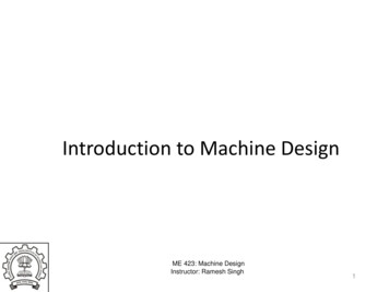
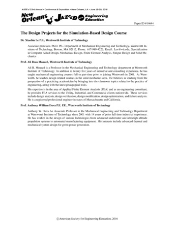
4. Design Specifications Delivered power of 20 hp with driven device that is treated as “light-shock” loadings Input speed of 1800 rpm Gear Ratio of 7.2 with 1% variation Pressure Angle of 200 Design Life of 4,000 hours Factor of safety of 3.25 for the static design of the shaft Factor of safety of 1.25 for the fatigue design of the shaft Reliability index of 0.9These design specifications were the guidelines that indicated if the design was being designedas specified. The design specifications affected how the gears, shafts, mechanical key, bearings,and housing designs were created. The following sections have detail descriptions of thedifferent parts that create a gearbox.5. Design and Analysis5.1. Gear DesignThe first component in creating a gear box are the gears. Gears are rotating objects thattransfer energy from one place to another. In order to create a gear one must analyze the way itlook so that it close to the gearbox layout. The figure (Appendix: Major Project WorksheetInstructions) shows that there are two gears present. One is the pinion which is a small size gearthat is next to a large gear. The gears would transfer power from one gear to another. Thefollowing is a spreadsheet created through Excel in order to determine the shape of the gears:
Figure 1.0: Gear Analysis
The first parameter in determining the size of the gear is the designated power (PDes). Thefollowing equation was used in order to solve for Pdes:Pdes K0 PWhere K0 is the designed factor and P is the power delivered. This would help determinethe diametrical pitch using Table From Lecture 16 Slide 26. Based on the calculationsobtained, it was concluded that the diametrical pitch Pd was 8 tooth/inch for each gear.Another parameter that was used was the tooth thickness t and that was calculated byusing the following formula:𝑡 𝜋2 𝑃𝑑Furthermore, the face width, which is the width of the tooth, was calculated using thefollowing equation:𝐹 12𝑃𝑑This was then followed by verifying the gear ratio so that one could determine thenumber of teeth for each gear. Based on the minimum gear ratio of 7.128, it was concluded thatthe pinion gear had to have 17 teeth (NP). Whereas, the larger gear had maximum gear ratio of7.272 which means the larger gear had about 122 teeth (NG). Based on the number of teeth thefollowing equations were used in order to determine the pitch diameter of each gear:𝐷𝑃𝑖𝑛𝑖𝑜𝑛 𝑁𝑃𝑃𝑑
𝐷𝐺𝑒𝑎𝑟 𝑁𝐺𝑃𝑑By determining the dimensions of the gears the next question that arises is what thematerial the gears are made out of? The next part of the gear analysis analyzes the AGMABending Stress, Allowable Bending Stress, AGMA Contact Stress, Allowable Contact Stress,and Hardness so that the material is determined.Mike add your excel spread sheet here.AGMA Bending Stress:In order to choose the material the gears were made out of, the AGMA bending stress andthe AGMA contact stress first had to be calculated. The required hardness was then calculatedaccording to the required bending and contact stress in order to determine the proper materialwith the proper heat treatment to satisfy the required hardness. The AGMA bending stress wascalculated using the equation:𝜎 𝑊𝑡 𝐾𝑂 𝐾𝑉 𝐾𝑆 𝑃𝑑𝐹 𝐾𝑀 𝐾𝐵𝐽,Where 𝑊𝑡 is the tangential force, 𝐾𝑂 is the overload factor, 𝐾𝑉 is the dynamic factor, 𝐾𝑆 is thesize factor, 𝑃𝑑 is the diametral pitch, 𝐹 is the face width of the gear, 𝐾𝑀 is the load distributionfactor, 𝐾𝐵 is the rim thickness factor and 𝐽 is the geometry factor for bending stress for both thepinion and the gear.The first part of the equation is the tangential force on the gear, 𝑊𝑡 . This was calculatedby dividing the power supplied to the gears, 𝑃 by the pitch-line velocity, 𝑉𝑡 with the pitch-linevelocity being equal to pi multiplied by the pitch diameter and by the input pinion speed.
𝑉𝑡 (𝜋 𝐷𝑝 𝑛𝑝 )/12𝑊𝑡 33000 𝑃𝑉𝑡With 12 and 33000 being conversion factors from inches to feet and horsepower to feet perminute respectively.𝐾𝑂 is the overload factor which is the probability that application-specific conditions suchas vibrations or shocks would cause peak loads to be greater than the tangential force, 𝑊𝑡 beingapplied to the teeth on the gears. They are determined by the power source and for this gearbox,the overload factor was given as 1.5.𝐾𝑉 is the dynamic factor which is based upon the fact that the actual load is high than thetransmitted load alone and determined by the gear quality and pitch line velocity values. Thedynamic factor was calculated by the equation:𝐾𝑉 [𝐴 𝑉𝑡𝐴𝐵]With A and B being values that are calculated through other equations with the gear qualitynumber. A was calculated by the equation:𝐴 50 56(1 𝐵)And B was calculated by the equation:2𝐵 0.25(12 𝑄𝑣 )3In this equation, 𝑄𝑣 is the gear quality number and for this gearbox the given gear qualitynumber is 5.
𝐾𝑆 is the size factor and as the AGMA indicates, it can be taken as 1 for most gears butfor gears with a large face width, a value greater than 1 is recommended. For this gearbox, theface width was relatively small so a size factor of 1 was used.𝑃𝑑 is the diametral pitch of the gears and a value of 8 teeth per and inch was given as adesign specification for the gearbox.𝐹 is the face width which is the surface of a gear tooth from the pitch circle to theoutside circle of the gear. For this gear box, the face width was calculated using the equation:12𝐹 𝑃𝑑Which gave the face width a value of 1.5 inches.𝐾𝑀 is the load distribution factor. The load distribution factor was calculated using theequation:𝐾𝑀 1.0 𝐶𝑝𝑓 𝐶𝑚𝑎Where 𝐶𝑝𝑓 and 𝐶𝑚𝑎 are the pinion proportion factor and the mesh alignment factor respectively.𝐶𝑝𝑓 is calculated using the equation:10𝐶𝑝𝑓 𝑃 .025, 𝑤ℎ𝑒𝑛 𝐹 1𝑑And by:10𝐶𝑝𝑓 𝑃𝑑 .0375 .0125𝐹 , 𝑤ℎ𝑒𝑛 1 𝐹 15𝐶𝑚𝑎 was calculated using the equation:𝐶𝑚𝑎 .247 .0167𝐹 .765 10 4 𝐹 2
𝐾𝐵 is the rim-thickness factor which Accounts for bending of rim on a gear that is not solid. Theequation for calculating the rim-thickness factor is:2.242 𝑚 𝐵 1.21.6ln()𝐾𝐵 {𝑚𝐵𝑚 𝐵 1.21𝐽 is the geometry factor for bending stress for both the pinion and the gear which is amodification factor that is based upon both the tooth geometry and the stress concentration. Inorder to calculate it for the pinion and the gear, Figure 14-6 (lecture 14 slide 45) was used inconjunction with the number of teeth for both the pinion and gear.Allowable Bending Stress:The allowable bending stress number equations for both the pinion and gear are used tocalculate the allowable bending stress number, 𝑆𝑡𝑝 and 𝑆𝑡𝑔 , for the material that the gears will bemade out of in order to make sure that the material is able to withstand the bending stress causedby the pinion and gear. The equation for the allowable bending stress for the pinion is:𝑆𝑡𝑝 (𝑆𝐹 𝐾𝑅 𝐾𝑇 𝜎𝑃 )/𝑌𝑁𝑃And the equation for the allowable bending stress for the gear is:𝑆𝑡𝑔 (𝑆𝐹 𝐾𝑅 𝐾𝑇 𝜎𝐺 )/𝑌𝑁𝐺Where 𝑆𝑡𝑝 and 𝑆𝑡𝑔 are the allowable bending stress numbers for the pinion and gearrespectively, 𝑆𝐹 is the factor of safety for bending, 𝐾𝑅 is the reliability factor, 𝐾𝑇 is thetemperature factor, 𝜎𝑃 and 𝜎𝐺 are the bending stresses for the pinion and gear respectively, and𝑌𝑁𝑃 and 𝑌𝑁𝐺 are the stress cycle factors for the pinion and the gear respectively.
𝑆𝐹 is the first variable in the equation for the allowable bending stress number and is thefactor of safety for bending for the pinion and the gear. For this gearbox, the factor of safety waschosen to be 1.25.𝐾𝑅 is the reliability factor and it was calculated to be .85 from table in the appendixusing the reliability of .90 which was specified in the design specifications.𝐾𝑇 is the temperature factor and was gives as a value of 1.𝜎𝑃 and 𝜎𝐺 are the bending stresses for the pinion and gear respectively and werecalculated using the bending stress equation shown above.𝑌𝑁𝑃 and 𝑌𝑁𝐺 are the stress cycle factors for the pinion and the gear respectively. Theywere calculated using the equation:𝑌𝑁 1.3558(𝑁) .0178Where 𝑁 is the number of cycles of loading and was be calculated using the equation:𝑁 60 𝐿 𝑛 𝑞Where 𝐿 is the design life in hours, 𝑛 is the rotational speed in rpm, 𝑞 is the number ofload applications per revolution which for this gear box is 1 and 60 is the conversion factor fromhours to minutes. The equation for the stress cycle factors for the pinion and the gear wasobtained from Figure 14-14 (lecture 14 slide 27) in the appendix.AGMA Contact Stress:The AGMA contact stress is calculated in a similar manner to the AGMA bending stressbut not exactly. It was calculated using the equation:
𝐾𝑀𝜎 𝐶𝑝 𝑊𝑡 𝐾𝑂 𝐾𝑉 𝐾𝑆 (𝑑𝑝) 𝐹𝐶𝑓𝐼Where 𝜎𝑃 is the contact stress for the pinion, 𝐶𝑝 is the elastic coefficient, 𝑊𝑡 is the tangentialforce, 𝐾𝑂 is the overload factor, 𝐾𝑉 is the dynamic factor, 𝐾𝑆 is the size factor, 𝐾𝑀 is the loaddistribution factor, 𝑑𝑝 is the pitch diameter of the pinion, 𝐹 is the face width, 𝐶𝑓 is the surfacecondition factor, and 𝐼 is the geometry factor for pitting resistance.𝐶𝑝 is the elastic coefficient and for this gearbox, steel was chosen based on the calculatedvalues for the bending stress and from the data from table in the appendix .𝐶𝑓 is the surface condition factor which accounts for detrimental surface finish. Thevalue of 1 was used for it based on the fact that the value of 1 is used for normal commercialgears.𝐼 is the geometry factor for pitting resistance which was determined to be .108 by usinggraph Figure 9-23 (lecture 14 slide 46) in the appendix in conjunction with the gear ratio of 7.2and the number of teeth on the pinion which is 17.Allowable Contact Stress:The allowable contact stress number equation for both the pinion and gear are used tocalculate the allowable contact stress number, 𝑆𝐶𝑃 and 𝑆𝐶𝐺 , for the material that the gears will bemade out of in order to make sure that the material is able to withstand the bending stress causedby the pinion and gear. The equation for the allowable contact stress for the pinion is:𝑆𝐶𝑃 𝑆𝐻 𝐾𝑇 𝐾𝑅𝑍𝑁𝑃 𝐶𝐻And the allowable contact stress for the gear is:
𝑆𝐶𝐺 𝑆𝐻 𝐾𝑇 𝐾𝑅𝑍𝑁𝐺 𝐶𝐻Where 𝑆𝐶𝑃 and 𝑆𝐶𝐺 are the allowable contact stress numbers for the pinion and gear respectively,𝑆𝐻 is the factor of safety for contact, 𝐾𝑇 is the temperature factor, 𝐾𝑅 is the reliability factor, 𝑍𝑁𝑃and 𝑍𝑁𝐺 are the stress cycle factors for Contact Stress for the pinion and the gear respectivelyand 𝐶𝐻 is the hardness-ratio factor.𝑆𝐻 is the factor of safety for contact for the pinion and the gear and for this gearbox, thefactor of safety was chosen to be 1.25.𝑍𝑁𝑃 and 𝑍𝑁𝐺 are the stress cycle factors for Contact Stress for the pinion and the gearrespectively. They were calculated using the equation:𝑍𝑁 1.4488(𝑁) .023Where 𝑁 is the number of cycles of loading and was be calculated using the equation:𝑁 60 𝐿 𝑛 𝑞Where 𝐿 is the design life in hours, 𝑛 is the rotational speed in rpm, 𝑞 is the number of loadapplications per revolution which for this gear box is 1 and 60 is the conversion factor fromhours to minutes. The equation for the stress cycle factors for the pinion and the gear wasobtained from graph Figure 14-15 (lecture 14 slide 28)in the appendix.𝐶𝐻 is the hardness-ratio factor which accounts for the increase in the gear capacity withregards to the pitting resistance. For the gearbox, the hardness-ratio factor was determined to be1.
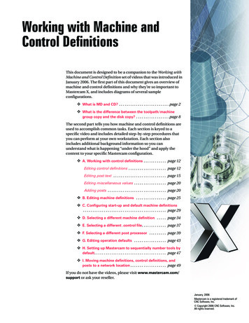
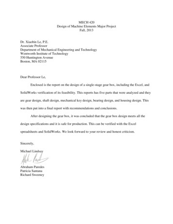
Hardness:After all these values were calculated, the hardness was then determined for the pinion and thegear by the equation:𝑆𝐶 349𝐻𝐵 34300From graph Figure 14-5 (lecture 14 slide 20).Based on the hardness the material of both the pinion and the gear is AISI 1030 Q&T at400 degrees Fahrenheit.5.2 Shaft AnalysisFor the design of the shaft, the first step was to choose a layout. One of the shaft layoutsthat was considered for the gearbox design was the shoulder layout. In this layout, there are twobearings and two shoulders on each side which block axial movement. Moreover the designlayout has a rotating ring which is used in order to keep the gear in place.Another shaft layout is the Shoulder Shoulder Spacers layout. In this layout there are twobearings on each side and one shoulder and spacer on one side. This varies from layout 1 ashaving a spacing enables the gear to move at a faster rate thus transfer power quicker.Based on an extensive analysis it was concluded that shaft design layout #2 was the layoutchosen for the final design as the group concluded that more power transfer would create a moreefficient gearbox. This layout was used for both the input and output shafts. The chosen materialfor the shafts is AISI 1030 steel quenched and tempered at 400 Fahrenheit. The final layout ofthe shaft is shown below:
Figure: Shaft layout
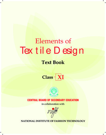
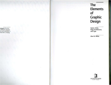
The next step in designing the shaft was to create torsion, shear force, and momentdiagrams of the shaft. To do this, the velocity was calculated based on the pitch diameter andinput speed:Vt d p n 2.125 1800 1001.383(ft/min)1212The velocity and output power were used to calculate the radial and tangential force onthe shaft:Wt 33000P20 33000 659.0887(lbs)Vt1001.383Wr Wt tan 659.0887 tan 200 239.8887(lbs)The radial and tangential force on the shaft were then used to calculate the total force andtorque on the shaft at point E:FR Wt 2 Wr 2T Wtdp2 659.0887 659.0887 2 239.8887 2 701.3876(lb)2.125 700.2817(lb in)2The numbers used in the above calculations are for the input shaft, but the output shaftwas analyzed using the same method and equations. The final torsion, shear force, and momentdiagrams for both shafts are shown below:
Figure: Input shaft torsion, shear force, and moment diagrams
Figure: Output shaft torsion, shear force, and moment diagrams
Using these diagrams, the required minimum shaft diameters were determined based onstatic analysis. This was done using the following equation: 16ns 4( K t M a ) 2 3( K ts Tm ) 2 d S y 1/3In this equation, ns is the factor of safety, Kt is the stress concentration for bendingmoment under static loading, Ma is the bending moment, Kts is the stress concentration fortorsion, Tm is torsion, and Sy is the yield strength of the material. For the static analysis, a factorof safety of 3.25 was used. The values of Kt and Kts were determined using Table 7-1, which canbe found in the appendix.d1 was analyzed at two critical areas: the keyseat at A and the fillet at C. d2 had to be atleast 1/8th of an inch larger than d1 and d3. d3 was analyzed at critical areas D and E. d4 only hadto be analyzed at the fillet at F. The minimum diameters based on static analysis are as follows:d1 Criticalarea Ad1 Criticalarea Cd21.992168 in1.496316 inlargerthan d1and d3ind3 criticalarea D1.318042 ind3 criticalarea E1.663651 ind40.532286 inFigure: Input shaft diametersd1Criticalarea Ad1Criticalarea Cd21.031688 in0.777858 inlargerthan d1and d3ind3 criticalarea D0.705596 ind3 criticalarea E0.95277 in0.542939 ind4Figure: Output Shaft Diameters
The next step in designing the shaft was to calculate the minimum diameter based onfatigue analysis. This was done using the following equation: 16n fd 2K f M a3K fs T m Se Sut 1/ 3In this equation, nf is the factor of safety, Kf is the fatigue stress concentration factor forbending, Kfs is the fatigue stress concentration factor for torsion, Se is the endurance limit of thecomponent for cyclic bending stress, and Sut is the ultimate strength of the material. For thefatigue analysis, the factor of safety is 1.25.In order to calculate Se, the following set of equations was used:Se ka kb kc kd ke k f Se' ;Se' 0.5Sut ;k a 2.70 Sut 0.265 ;kb 0.879d 0.107 ;kc 1;k d 1;k e 0.814 ;k f 1;
Here, ka is the surface factor for machined surface, kb is the size factor, kc is the loadfactor, kd is the temperature factor, ke is the reliability factor, and kf is the miscellaneous factor.Kf and Kfs were calculated using the following equations:K f 1 q( Kt 1) ;K fs 1 q(Kts 1) ;For the analysis at the keyseats, Kt and Kts are the same as those used for the staticanalysis, and q is equal to 0.8. For the analysis at the fillets, Kt and Kts are found using a stressconcentration resource called eFatigue, and q was determined using the following equations: a ; where r is fillet radiusq 1 1 r a bending 0.246 3.08(10 3 )S ut 1.51(10 5 )S ut2 2.67(10 8 )S ut3 ;a torsion 0.190 2.51(10 3 )S ut 1.35(10 5 )S ut2 2.67(10 8 )S ut3 ;The equation fora bending is used when calculating Kf, and the equation fora torsion isused when calculating Kfs.Determining the final dimensions of the input and output shafts was an iterative process.First, the fatigue analysis was done using the diameters determined by static analysis. The newdiameters found in this fatigue analysis were then used to determine the keyseat dimensions andwhich bearings to use. When this was done, the shaft was modified according to the keyseat andbearing analysis. The static and fatigue analysis were then repeated using these modifications.This entire process was repeated until a set of diameters was found for the shafts which satisfied
static, fatigue, bearing, and keyseat analysis. This process was done in excel to keep thecalculations organized and to save time.The final diameters of the shaft are as follows:d1d2d3d41.5 in1.635 in1.25 in1.000 inFigure: Input shaft diametersd12.25 ind22.375 ind31.687 ind41.125 inFigure: Output shaft diametersThese diameters were then used in order to determine the size of the mechanical key.
5.3 Mechanical Key DesignAdd your part here Patricia.5.4 Bearing DesignBefore starting with the bearing analysis, one must define the application of bearings.The main design purpose of the bearings is to locate the shaft and provide less friction shaftrotation. Since there is an input and output shaft, and the shaft layout required two bearings foreach shaft, meaning one had to pick four bearings from the website McMaster-Carr. To choosethe proper bearings, it was recommended to use the bearings using the ABEC 1 tolerances.ABEC 1 are “dimensional tolerance standards in hard-to-find inch sizes, these quiet-running,electric-motor-quality bearings handle radial (perpendicular to the shaft) loads and smallamounts of angular misalignment. Temperature range is –40 to 248 F” (Mc-Master-Carr). Forboth shafts one ended up choosing 2/4 bearings using the ABEC 1 tolerances. The following is adetailed analysis that describes how one came to the conclusion that different kinds of bearingsare needed to be introduced in order for the design specifications to be met (Note: This procedureis the same for the input bearings and output bearings).The first equation used was to determine the design life (LD) of the bearings. Thefollowing equation was used to determine the design life:𝐿𝐷 60 ℎ 𝑛Where h is the design life of the gears and bearings, and n is the input speed. Not onlywas LD determined, but the department head informed one that LD LD10 making it simpler tosolve for other necessary parameters. For example, now was able to calculate the design life ratioof LD and L10 named xD. The following equation was used in order to calculate xD:
𝑥𝐷 𝐿𝐷𝐿10This was followed by selecting either a tapered or ball and straight roller bearing. Basedon the choice of the bearing, the values from the table on Lecture 18 Slide 26 was used in orderto obtain the values L10,x0, ɵ, and b. Another parameter that the department gave to criticismwas af and based on the fact that af had to be in between 1.25-1.50, 1.35 seemed to be the bestoption for af as it was the average of the expected af. This was then followed by selecting a,which consisted of either 10/3 for roller bearings or 3 for ball bearings. Furthermore, now onewas presented with the two most important concepts that would ultimately determine the bearingand they are the dynamic loading C10 and the minimum diameter dminimum shaft. To find thedynamic loading C10 one had to use the following formula:1/𝑎𝐶10 𝑎𝑓 𝐹𝐷 [𝑥𝐷𝑥0 (ɵ 𝑥0 )(1 1]𝑏𝑅𝐷 )The only variable in the above formula that has not been defined is RD with is the indexreliability of 0.9. Not only is C10 is an important factor, but CD10 is important to consider in orderto prove that if CD10 C10 then the design specifications are being met. The following is theequation for CD10:𝐶𝐷10 𝑎𝑓 𝑉 𝐹𝐷 [𝐿𝐷 1/𝑎]𝐿10After measuring the dynamic load, one had to compare the diameter of the static (dminimumshaft)loading with the diameters from the bearings McMaster provided. In order to make a final
decision, the dynamic loading C10 had to be more than the calculated value. Not only was C10analyzed, but the diameter of the shaft also had to be greater than dbore.Based on the calculations for determining the size of the bearings, one used an openbearing of R24 and a high load open 2780T26 for the input shaft. Whereas, for the output shafthad a steel tapered-roller bearings, and an open bearing of size R18. These equations give rise tothe concept of creating a housing for the assembly.5.4 Housing DesignThe housing is the part of the gear box that holds everything together. For our design, wepicked a simple design in which the shaft bearings of the shaft rest on top of the housing. Inorder to determine the proper dimensions of the housing, some rough sketches were made, whichcan be found in the appendix.The distance between both shafts must be the half the pitch diameter of the input shaftplus half the pitch diameter of the output shaft. This ensures that the gears come together in theright position so that they can work efficiently. One requirement for our design was that thewalls of the housing must be at least 0.5 inches away from the moving parts of the gear.Therefore, the each shaft had to be half of the pitch diameter plus 0.5 inches away from thewalls.For the top view, the dimensions of the bearing holders were determined based on thedimensions of the chosen bearings. The width of the housing was determined by the lengths ofthe shafts. The SolidWorks model for the housing can be found in the next section.
6. Drawings for components and assemblies6.1. Part DrawingsFigure: Pinion Drawing
Figure: Output gear drawing
Figure: Input shaft drawing
Figure: Output shaft drawing
Figure: Input key
Figure: Output key
Figure: R24 Bearing
Figure: R18 Bearing
Figure: 387A Bearing
Figure: 2780T260 Bearing
Figure: Housing SolidWorks Model
Figure: Gearbox Assembly
Figure: Gearbox Assembly exploded view
Figure: Gearbox Bill of Materials
7. Findings, Discussion and ConclusionsBased on the presented calculations, graphs, and tables it is found that the current designdoes not meet the all the major design specifications. This means the design specifications weremet for all parts of the carjack except the link bar. This could be due to the shape of the link ormaterial.While this project did not required a redesign, what could have been done was to use amaterial such as Alloy Steel and used the FEA Simulation through SolidWorks in order todetermine if the material was the problem.Moreover, this shows that the project was limite
DESIGN OF MACHINE ELEMENTS MECH420 Major Project Single-stage Gear Box By: Michael Lindsay, Abraham Paredes, Patricia Santana, Richard Sweeney Department of Mechanical Engineering and Technology College of Engineering and Technology Wentworth Institu