Transcription
Computational Fluid Dynamics-BasedStudy of an Oilfield Separator—Part I: A Realistic SimulationAli Pourahmadi Laleh and William Y. Svrcek, University of Calgary, and Wayne D. Monnery, Chem-Pet Process Tech LimitedSummaryA realistic computational fluid dynamics (CFD) simulation of afield three-phase separator has been developed. This realistic CFDsimulation provides an understanding of both the microscopic andmacroscopic features of the three-phase separation phenomenon.For simulation purposes, an efficient combination of two multiphase models of the commercial CFD software, Fluent 6.3.26(ANSYS 2006a), was implemented. The flow-distributing bafflesand wire mesh demister were also modeled using the porous mediamodel. Furthermore, a useful approach to estimating the particlesize distribution in oilfield separators was developed. The simulated fluid-flow profiles are realistic and the predicted separationefficiencies are consistent with oilfield experience.IntroductionOnce a crude oil has reached the surface, it must be processedso that it can be sent either to storage or to a refinery for further processing. In fact, the main purpose of the surface facilitiesis to separate the produced multiphase stream into its vapor andliquid fractions. On production platforms, a multiphase separatoris usually the first equipment through which the well fluid flows,followed by other equipment such as heaters, exchangers, and distillation columns. Consequently, a properly sized primary multiphase separator can increase the capacity of the entire facility.CFD simulation is routinely used to modify the design and toimprove the operation of most types of chemical process equipment, combustion systems, flow measurement and control systems, material handling equipment, and pollution control systems(Shelley 2007). There are two approaches to developing CFDmodels of a multiphase flow: the Euler-Lagrange approach and theEuler-Euler approach. In the Euler-Lagrange approach, the continuous fluid phase is modeled by solving the time-averaged NavierStokes equations, and the dispersed phase is simulated by trackinga large number of droplets through the flow field based on Newton’s second law. The Euler-Euler approach, on the other hand,deals with the multiple phases as continuous phases that interactwith each other. Because the volume of a phase cannot be occupied by the other phases, phase-volume fractions are assumed to becontinuous functions of space and time, and their sum is equal to 1.The literature on the critical unit operation of multiphase separators abounds with macro studies and design methodologies for twoand three-phase vertical and horizontal separators. However, thereare very few papers that focus on the micro details of the actual separation process. The most important features of these studies havebeen reviewed as follows. Hansen et al. (1993) presented the simulation results of the developed CFD code, FLOSS, for an industrialCopyright 2012 Society of Petroleum EngineersOriginal SPE manuscript received for review 29 November 2010. Revised manuscriptreceived for review 10 February 2011. Paper (SPE 161212) peer approved 22 March 2011.scale three-phase separator. The separator of interest, with diameterof 3.33 m and length of 16.30 m, was the first stage of the threestage-dual-train production process installed on Gullfaks-A offshore platform. The production on the Gullfaks-A platform startedsuccessfully in 1986–87. However, because of a projected increasein the water production, several separation inefficiencies such aswater-level control, emulsion problems, and increased impuritieswere experienced in the following years. In order to develop an indepth understanding of this complex three-phase separation process, Hansen et al. (1993) developed a CFD model of the separator.Because of the problem scale and importance, and also becausealmost all of the operating and physical parameters required forCFD simulations have been provided by Hansen et al. (1993), thissignificant case was selected for comprehensive CFD studies inthe present work. Hallanger et al. (1996) developed a CFD modelfor a three-phase (free gas, oil dispersed water, and free water)separator by extension of the two-fluid model. The mixture modelwas used for modeling the oil phase while the water droplets weredistributed through different droplet size classes. The momentumequation for the mixture phase together with the continuity equations for each class was solved. Interaction between disperseddroplets, such as coalescence and breakup, was neglected. Thepressure-correction approach with some adjustments for the mixture phase was used to obtain the numerical solution of the system.The model was used to simulate a first-stage separator equippedwith a deflector baffle, two perforated baffles, a demister, and aweir plate. The CFD results indicated that most of the smaller waterdroplets would remain in the oil phase. The CFD results in terms ofconcentrations of water droplets in the oil outlet vs. oil-residencetime compared well with empirical data. The effects of inlet distributors and distributing baffles on reducing the size and weight ofseparation trains were reviewed by Frankiewicz et al. (2001). Thesensitivity of the installed vortex cluster to the inlet flow rate hasalso been demonstrated. This paper did not include any information on the developed CFD models. Frankiewicz and Lee (2002)studied the influence of inlet nozzle configuration, flow distributors, perforated plates, and outlet nozzles on the flow pattern in twoand three-phase oilfield separators. They used Fluent 6.0 softwareand took the inlet nozzle, the inlet momentum breaker, perforatedplates, weir or bucket plates, and outlet nozzles as the key affectingcomponents. To increase the effective liquid retention time, CFDstudies indicated that a second perforated plate just upstream of theoutlet nozzle was required. Moreover, the use of composite plateelectrodes and the shrouded pipe distributors increased the capacityof the operating separator to some 67% owing to an improved plugflow regime. Lee et al. (2004) evaluated the design of internals fora three-phase separator to mitigate sloshing of liquid phases causedby the offshore platform location. In order to prevent the waterphase from being pulled up toward the oil weir, on the basis of theperformed CFD simulations, a perforated baffle was designed andplaced near the oil weir, the open areas of two preceding baffleswere decreased, and the configuration of the oil weir was modified.December 2012 Oil and Gas Facilities57
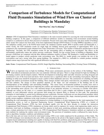
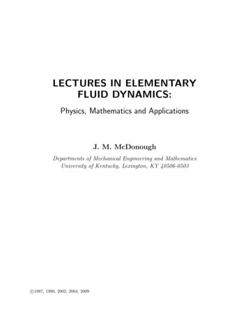
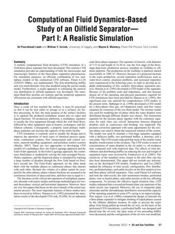
1630.1 cm380 cm303 cmInletzGasOulet338.6 cm332.8 cm295.05 cmyx123.4 cm60 cm92.5 cm87.5 cmWaterOuletOilOuletFig. 1––Geometrical specifications of the Gullfaks-A separator (Hansen et al. 1993).TABLE 1—QUALITY OF THE MESH PRODUCED FOR THE GULLFAKS-A SEPARATORIN THE GAMBIT ENVIRONMENTNumber of CellsMaximum SquishMaximum SkewnessMaximum Aspect Ratio8848470.7481820.89587344.1708Skewness of the Produced MeshSkewness rangeDensity of cells0–0.2079.0416%0.20–0.4015.4785%These improvements led to eliminating the water spillover problem.Unfortunately, the details of the CFD simulations and the obtainedsolutions were not presented in the paper.A vertical two-phase separator equipped with a deflector baffleand a vane-type demister was modeled by Swartzendruber et al.(2005) using Fluent software. They focused on the quality of gasflow distribution through the demister. Again, unfortunately, details of the developed CFD model are missing from the paper. Onthe basis of the resulting fluid-flow streamlines, two changes weredevised to mitigate the uneven flow distribution in the vane demister. Thus, the deflector baffle was moved away from the inlet andinstalled parallel to vane demister, and a 90 elbow with turningvanes was installed between the inlet and the deflector baffle. Luet al. (2007) studied the effectiveness of perforated plate baffles forimproving the separation performance of a FWKO separator. TheFluent 6.2 software was used for simulation, but the multiphasemodeling was based only on a balance between available computational resources and model capabilities. The velocity contours offluid flows visually confirmed that the previous large flow circulations were broken into small ones by installing the perforated platebaffles. Furthermore, the mean residence time of fluid particles wascalculated and showed an increase from 630 to 980 seconds for thewater phase and from 520 to 745 seconds for the oil phase becauseof the installed distributing baffles. Lee et al. (2009) discussed several engineering judgments and the corresponding CFD verifications to revamp the phase-separation inefficiencies experienced ina major oil production facility. Their debottlenecking studies ledto some suggestions for the weir height, liquid levels, and configuration and position of distribution baffles. Again, details of theCFD models, developed through the Fluent 6.3.26 software, havenot been provided in the paper. The simulation results showed thatthe applied improvements mainly influenced the water phase, andthe fluid-flow streamlines visually confirmed that the large flowcirculations were broken into small weak ones by implementing thesuggested modifications.58Oil and Gas Facilities December 20120.40–0.603.8489%Developed CFD Model0.60–0.801.6285%0.80–1.00.0025%Physical Model. Fig. 1 provides the geometrical specifications ofthe Gullfaks-A separator as provided by Hansen et al. (1993). AsFig. 1 shows, a spherical deflector baffle was used to break themomentum of the inlet three-phase fluid flow entering the vessel asa high-momentum jet. The upper part of the vessel was equippedwith internals, including flow-distribution baffles and a demister, toenhance the separation of liquid droplets from gas.In this study, building the physical model and generating thecorresponding mesh system were performed in the Gambit 2.4.6(ANSYS 2006b) environment. In order to have a discretized modelwith “good” grid quality, the mesh-generation process was completed in a step-by-step sequence. The vessel was split into areasand the inlet nozzle, deflector baffle, splash plate, weir, and outletnozzles were first discretized. In doing so, the edges of nozzles andother internals were discretized before the mesh generation for theseparator surfaces and volumes. Then, the cylindrical part of thevessel was discretized such that some cells in this part were separated and referred to as the porous media, and did include meshfor distribution baffles and the demister pad. The horizontal surrounding surfaces of each baffle (with thickness of 0.02 m) andthose of demister pad (with thickness of 0.15 m) were assumed tobe flat surfaces. Therefore, in the cylindrical part of the vessel, thegrids must be fine enough and arranged horizontally in regular andconstant intervals. After generating the mesh for the cylindrical partof the vessel, the remaining parts of the vessel were “swept” by theGambit mesh generation tool. Mesh elements were generally hexahedral. However, for regions with complex geometry (i.e., the inletand outlet nozzles), tetrahedral elements were necessarily used.The global quality of the produced mesh in terms of number ofcells, maximum cell squish, maximum skewness, and maximumaspect ratio are presented in Table 1, and Fig. 2 includes screenshots of the generated model in the Gambit environment. Furthermore, to ascertain the quality of the generated mesh, the cell skewness was evaluated and, as shown by the mesh results of Table 1,only a negligible fraction of cells (0.0025%) was of poor quality.However, the grids with a cell skewness factor greater than 0.8 were
Fig. 2––Physical model and mesh generated for the Gullfaks-A separator in the Gambit environment.TABLE 2—PHYSICAL PARAMETERS OF FLUIDS IN GULLFAKS-A SEPARATORPROVIDED BY HANSEN ET AL. (1983)1988 Production Rate(m3/h)GasOilWaterOperating ConditionsFuture Production Rate(m3/h)16401640138118401244287Temperature 55.4 C; pressure 6870 kPaconverted to polyhedral grids. Although this minor modificationdid not reduce the maximum values reported in Table 1, the numberof cells was reduced from 884,847 to 884,805.Material Definition. The physical parameters for the fluids inthe Gullfaks-A separator are taken from Hansen et al. (1993) andpresented in Table 2. Because interfacial surface tensions werenot given in the original paper, estimated values were used. Forthis purpose, a hydrocarbon mixture was defined in HYSYS 3.2(AspenTech 2003) to simulate the oil phase. The criterion for 0e–55.25e–34.30e–4ting the composition of the mixture was the accuracy of the mixture density and viscosity at operating temperature and pressurecompared to the values given in the original study. Using the PRequation of state and the TRAPP model, the density and viscosityof the mixture were estimated to be 783.59 kg/m3, and 0.005296Pa·s, respectively, with an estimation error for the oil density andviscosity of 5.76 and 0.88%, respectively. Thus, it was assumed thatthe oil/gas surface tension estimated by HYSYS was reasonable,and a surface tension of 0.0238 N/m was assumed for the oil/gasinterface. The assumed value compared well with the oil surfaceDecember 2012 Oil and Gas Facilities59
tension range of 0.023 to 0.038 N/m at 20 C proposed by Streeterand Wylie (1985). HYSYS 3.2 was also used for estimation of water/gas surface tension of 0.0668 N/m. Using the chart provided byHeidemann et al. (1987), the surface tension of pure water is 0.067N/m at 55.4 C, which is in agreement with the HYSYS estimate.Finally, the empirical study of Kim and Burgess (2001) was used toestimate the oil/water surface tension of 0.052 N/m at 25 C. Theynoted that although oil is a mixture of various hydrocarbons, eachone constituting hydrocarbon in contact with water has almost thesame interfacial surface tension. Thus, it was assume
CFD models, developed through the Fluent 6.3.26 software, have not been provided in the paper. The simulation results showed that the applied improvements mainly influenced the water phase, and the fluid-flow streamlines visually confirmed that the large flow circulations were broken into small weak ones by implementing the suggested modifications.File Size: 484KBPage Count: 12