Transcription
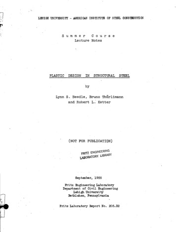
L.LmIGH UNIVERSITY - AMERICAN INSTITU'I!Bl OF STEEL CONSTBDCTlONI·'l Sum merC0 u r s eLecture NotesPLASTICDESIGNINSTRUCTURALSTEELbyLynn S. Beedle, Bruno Th rlimannand Robert L. Ketter(NOT FOR PUBLICATION)fRlTl ENG\NEER\NGlbABORATORY LIBRARYSeptember, 1955Fri tz Engineering LaboratoryDepartment of Civil EngineeringLehigh University:Bethlehem, PennsylvaniaFri tz Laboratory :Report No . 205.32
Copyright 1955byLynn S. BeedleBruno ThurlimannRobert L. KetterLehigh UniversityBethlehem,' Pennsylvania.:
.205.32"oTAB L EIntroduction0CON TEN T SF0 0 0 Page0.1 1. Fundamental Concept1.12. Flexure of Beams . .2.13. Upper andTheoremsLow r Bou d4. Equilibrium Method of Analysis4.15., Mechanisrp. Method of Analysis . . . . . . . . . . 5.16. Application of Mechanism Method6.17. Application of Mechanism Method7.18. Calculation 0f Deflections8.19. Modifications to Simple Plastic Theory. . . . . . .9.110. Connections, Design Details10.1,11. Problem of Structural ,Safety11.112. Rulesof Des'lgnI . 0 13. Analysis and Design Examples 00 00 12.1 0 14.114. Analysis and Design ExamplesNomencla ture .0 0013.1 0 0 0 0 0 15.1
0.1205·32I N T ROD U C T IONDuring the past twenty to twenty-five years a considerabl amount of research has been conducted on the ultimatestrength of ste,el structures.The'se studies have reve,aledpossibilities for the use of maximum (plastic) strength as abasis for structural design.on ynew, it issize"str oturalWhile the subject is by no meansin recent yearstha sufficient tests of large-members and frames have been performed andadequate analytical techniques developed to make the method ofpractical use.Many investigators have contributed prominently tothe application of plastic analysis to structural design.Some of the more recent advancements are due to the efforts ofJ. F. Baker, J. W. Roderick, M. R. Horne, and B. G. Near atCambridge University, England;and W. Prager, P. S. Symonds,and D. C. Drucker at Brown University in this country.Since 1946 a program of research has been underwayat Lehigh University under the sponsorship of the AmericanInstitute of Steel Construqtion, the American Iron and Steeli nst1tute,the Welding Research Council and the Navy Department(Office of Naval Research, Bureau of Ships, Bureau of Yardsand Docks).This program has included studies of the componentparts of rigid frames, an examination of possible modificationsto the "simple plastic theory I!, and development of practicaldesign procedures-- the program being supplemented where necessary by suitable tests using as-delivered rolled structuralshapes.
0.2205·32Vih2reastlv traditional basis of design for construc-tion purposes has been the lI e l as tic limit ll load, it has longbeen known that rigidly connected members possess a much greaterload-carrying capacity.The capacity of structural steel todeform. plastically allows an indeterminate structure to drawupon the reserve strength of its less heavily stressed portions.The application of plastic design is justified, firstof all, since it offers a satisfactory explanation of theobserved ultimate strength of steel structures.By plasticanalysis the engineer is able to determine the true loadcarrying capacity of the structure.On the other hand, byconventional elastic methods the true factor of safety againstultimate strength can and does vary significantly from onestructure to another.In the second place, plastic design has an appealon the basis of its simplicity.Most of the time-consuminganalysis of equations necessary for an elastic solution iseliminated.Further, lIimperfections ll that seriously affectelastic limit strength of a structure (such as spreading ofsupports, sinking Of supports, differences in flexibility ofconnections, residual stresses) have little or no effect uponthe maximum plastic strength.Finally, these techniques promise to produce substantial savings through the more economic and efficient useof steel and the savings in design office time.
205·32Plasticdesi nwill not replace all other designprocedures, since in some instances .criteria other than maximumplastic strength (such as fatigue, -instability, limiting deflection, etc.) may actually constitute the basis for design.In ordinary building construction, however, this is usuallynot the case.Therefore it can be expected that plastic designwill find considerable application, particularly in continuousbeams, industrial frames, and also in tier buildings.As amatter of fact, it has been reported that upwards of 175industrial frames have been designed in England by the plasticmethod -- also a school building and a five-story officebuilding.* * * * * * *In the following fourteen lectures the fundamentalconcepts of plastic analysis are presented.Specific plasticdesign techniques are described together with examples toillustrate their application.These lectures are supplementedby a series of demonstration tests of actual structures toillustrate the principles.At the end of each lecture areas are appropriate to the topic.giv nsuch referencesA list of general referencesis also included at the end of the notes.The authors wish to express their sincere appreciation for the helpfulness and cooperation of all members of theFritz Laboratory staff in the preparation of these lecture. notes.
205.32I'i.c'.0.4Geor'ge Heimberger prepared the drawings., Miss PatriciaTorres typed the manuscript and Miss Lucille Fox and Mrs. R.Walther reproduced and assembled the notes.The review of the manuscript by Mr. T. R. Higgins.,Director of Engineering and Research., and Mr. E. R. Estes.,Research Engineer., of the American Institute of Steel Construction was most helpful and is gratefully acknowledged.The demonstrations which supplement these notes wereprepared by members of the staff at Fritz Laboratory.Amongthese were George C. Driscoll (who had immediate charge of thedemonstrations)., S. J. Errera (Engineer of Tests)., Kenneth R.Harpel (Foreman) and his staff., I . J. Taylor (Instrumentation);A. W. Huber., Y. FUjita., G. Haaijer., M. W. White., B. C. Chapmantook charge of individual tests.Final y.,the authors wish to thank the AmericanInstitute of Steel Construction for making possible the offeringof this summer course and to acknowledge the helpful assistanceof Professor W. J. Eney., Head of the Civil Engineering Departl·.\ ntand. D:Lrector of Fritz Engineering Laboratory.
1.1205·32Lecture No'. 1FUN DAM E N TALSCOPE:CON C E P T SThe ductility of steel (basis for plastic analysis)is illustrated.Conventional (elastic) designdescribed and examples given to show that even theseprocedures are often based on implicit assumptionof plastic action under overstress.Ultimatestrength of several types of structures computed.Historical notes given on development of plasticdesign.OUTLINE:1.11. illCHANICALfROrERTIES OF STEEL2.CONVENTIONAL ELASTIC DESIGN3.CARRYING CAPACITY OF STRUCTURES4.HISTORICAL NOTESMECHANICAL PROPERTIES OF STEELSFig. 1.1 sho\i-lS typical tens"iJ.e; s t'res s ,;st'ra.in 'cu:c;/esof different types of steels which have structural applications:1.Carbon (A-7)2.r"layari - R3.otiscoloy4.Tiva5.Silicon6.T-lThe Figure is self-explanatory.from elastic range to yield level.Note sudden changeExtension bet't'Jeen
Fi9' 1.\l'Jote A yieid level;5 verypronounced. est 7tlJTYPICAL (J-E CUI2VES'\IScommon J.--.1\)1--'0 V1I--' ----wI\)100 ---Silicon (crult, :. 92.5 k.si)E/1'10.1(,. 1(00)(.10- 3f2A 4G %Tiva ( J"Ult. :: 50.S K.S',)Emo)(. I OOx 10- 360------ --\0QA :(00 10J.-.--.-- - - - - ----.-----40Corbon (OUIt: :: 57.5 k.si)CmaxQA :(03 c. 20o lGO){IO-3411.20.I-'I\)
1.3205.32(1.1)yielding and strain hardening varies from about 6 to 16times elastic strain at yielding.Remarkable is theductility (varies from 16% to 26%) at fracture.Ordinaryelastic design does not make a Itconsciousll use of thisremarkable property.llPlastic Design lt proposes to makeuse of the. ductility up to the point at which strainhardening commences (E Est).It may be mentioned thatexperimental evidence is almost exclusively collectedfor structural carbon steel.But. other types of steels,as shown in Fig,. ·l.l should lead essentially to the sameresult.1.2CONVENTIONAL ELASTIC DESIGNtt--- -------'Z/ LExample r:Elastic Analysis:l-:::p ---- ::"'" J Y3 L 8Ml 8I PLM2Maximum StressAllowable Load: (1.1) 2 PL27Allowable (working) StressLoad Producing Yielding:
1.4205·32(1.2)Factor of Safety:F Yield StressAllowable StressWhat does ordinary factor of safety,F mean?If the applied allowable load Pw' acting on theidealized structure (assumed dimensions, simplifiedstress distribution, material with minimum prescribed yield point etc.) is increased to F x Pw,the most stressed fiber has just reached the yieldstress cry.What is know about the actual carrying capacity?Before answering this question let us examinewhether or not elastic design actually adheresto the principle that no yielding should everoccur.Some examples:1. Connections:/' AS5uFr:med forces in rivets (eCJuol)Actual force in rl velsThe same 'is true for welded connections.Basis of design is not maximum stress but the strengthof connection as a wholel
205.32(1.2 Y2. Residual Stresses: (Cooling residuals)Possibility: crr from 1/3 to /3cryBending produces yielding of rlangetips at loads less than workingload 1 .Welded specimens show crr up to 80% of yield stress.3. Cambering, Straightening, Cold Bending*.,,-----. . .-r. Residualco::: - '"Stressesl-.: Loading*Loadingstresses Residual Stressf shape factor.See Lecture No.2.(.
1.6205.32(1.2)4. "Erection" Stresses:Forcing-in of ' members during ereqtion causes stresses not:accounted for in analysis.-100Many moreas stresscases longconcentrations secondarystresses etc. could be cited./Conclusions:1.Maximum stresses are very often larger than crw ' AyrUj2.Design of connections is actually based on failureload not on elastic concept. Pn. )lVe ,73.Asjustification ductility of material is advo-. cated. 5 t( vok.4.Why not take the nextstep and introduce ductility·in main member design in a "conscious" manner?These examples should be sufficient to cause readersome concern about adequacy of present elastic methods.However no real concern is necessary.Future lectureswill show that elastic design constitutes a "possible
,1.7205.32(1.2)equilibrium solution"which solution is always less than"eq l(or at mostto) the true ultimate load.{This iscalled a 1Ilower bound 11 of the ultimate "loa'Si . l.In the meanwhile it should now 'be evident that ,theactual carrying capacity of a structure is best describedby considering the ductility of the material.Such isthe basis for the fOllov'ling' section.,1.3,CARRYING CAPACITY OF STATICALLY DETERMINATE AND STAT:rcALLYINDETERJ.VlINATE:iSlJffiUCTlJRES ,',;Neglect purposely any possibility of instability ;rbrittlefracture.(See Lecture No.9)Simple schematic examples:1. Tension Bar:(Determinate System)Stress:(JALElongation PA(1.4)PL-EA-(1.5)P-Unrestricted Plastic rlowI:I5frain(e)Elostic Range
205.321.8(1.3)2. 3-Bar Truss:(Indeterminate System)Areas: Al A2 A3Lengths': Ll' L3 A'f2L2 12La) Elastic Solution:2Tl cos 45 0 T2Equilibrium:Compatibility:6. Lli2 PT2 (1.6)6. L2Solving:Tl P2 12?2 1/22PElastic Limit"':T2 AcryYield Load:Py 2 'V2Acry2 2P(1.9)2 "(2 (1.8)1.707 Acry(1.10)b) Elastic-Plastic Solution:Like statically deterniiilate- system but with constant ,.force of Acry,p
1·9205·32(1.3)c) Ultimate Load:Forces:Equilibrium:Note:Pu V2Acry Acry (1 '(2)Acry 2.4l4AOy (1.11)Compatibility condition dropped!!d) Load-deflection Curve:tI------'--- r---------"--n:6'2Unrestricfed plastic Flow! r--r-- ------- :I.Contained p/asfio Flowt ? ,E.lostiC l20ngeI!,.10(1.12)Yield Deflection:Deflection at Ultimate Load':'(6L 2)-y 2cry L(1.13)EUltimate Load Load at which unrestricted plastic flowsets in!Note.that deflection at ultimateload is same as yielddef ectionof
205.32(1.3)1.103. Rectangular, Simple Beam in Bending:t fLIz.fLiZPLMmax crmaxPL -4s4ca) Yield Load:Py 4 S cryL. (1.14)nAt Pgh:4f PuStress DistributionCross SectionWith further load increase, yielding penetrates towardcorresponding.internal moment is called the "pl as tic moment",and for the rectangular section is defined by the equation.bh2M ---wherecry zcry stiCModulusb) Ultimate Load:Pu. 4 z cryL(1.15)
1.11205.32(103)c) Ratio:"Plastification 11 *of cross section resulted in an increasein load of 50%.Note that this ratio depends only oncross-sectional dimensionSl4. Statically - Indeterminate Beam:RectangularCross sectionElastic Analysis:a) YieldLoad See Eq. (1.1)Eq. (1.2)(1.2)If P is increased further section(g)starts to yield andsimultaneously will rotate at a much faster rate thanpreviously.(Se - - - - - - - -Lecture No.2) Section will pick-up- - - - - - - - - - - -* The term "pl as tification"!· means attainment of yield stresson the entire cross-section. .),
1.12205·32(1.3)more moment until a final state is reached with plastic(M l M2 Mp )*':.,moments at Sections 1 and 2Z3 MpMz MpZ9 Pl/Lb) Ultimate Load:The corresponding ultimate load Pu can directly be obtainedfrom the-, above Figure:2Pu L (1 ) Mp9-3P 15 Mp 15 bh 2 cru2L 8 L y(1.16)c) Ratio:.Pu 25 2 08Py12This increase is due to two effects:1. PlastificatioR ofcross section(as in statically-determinate cases)2. Redistribution of Moments (possible only inindeterminate cases)*See "Nomenclature" for .momentconvent:i:on: :};).st tically
1.13205·32(1.3)In the following lectures general methods for determiningthis ultimate load-carrying capacity will be given.It may be of interest to indicate how "Plastic Design"developed to its present state.1.4HISTORICAL NOTES1914Kazinczy - Tests on indeterminate beams, conceptof "yield', hinge 1,1.1917U" " ., -n-IKist - Design procedures utilizing ultimate loadcapacity.1926Gr ning Difficulties with general loading(Shake-down problem).1928Maier-Liebnitz - Tests, Elastic-Plastic Analysis -General Interest.1931Girkmann - Discusses Portal Frames.1932Bleich H. -:' "Shake-down" Problem.1936,:IABSE - Congress,1936Cambridge University, Prof. Baker and1941Van den BroekBerl n.Co1le gues.
1.14205.32(1.4)1946Brown University, Prof. Prager and Colleagues.1946Lehigh University, Investigations. leading to designapplications.1948Hrennikoff - Theory of inelastic bending.
2.1205.32Lecture No.2FLEXURESCOPE:oFB E A M SObjective is to determine how a beam deforms beyondelastic limit under the action of bending moments,i.e., what is Moment-Curvature (M- ) relationship?It is shown how procedures of plastic analysis arebased on the formation of plastic hinges and subsequent redistribution of moment.Since structuralmembers and frames are usually acted upon by shearand direct forces (in addition to bending moments),the resulting stress-distributions are described.Since their effect on ordinary engineering structuresisusu llysmall, they are treated later as modifi-cations to Simple Plastic Theory (Lecture No.9).OUTLINE:2.11.ASSUMPTIONS AND CONDITIONS2.BENDING OF RECTANGULAR BEAM3.BENDING OF WF BEAM4.PLASTIC HINGE CONCEPT5.REDISTRIBurION OF MOMENT'6.SHEAR AND DIRECT STRESSESASSUMPTIONS AND CONDITIONS1.Strains proportional to distance from neutral axis(','plane" sectior'.s).
· 205' 322.2(2.1) .Idealized stress-strain relationship:2.-:::::-rn '--'"4.0r- ----b : 30I/):2 : ZO\.II: 10tf)I:r:-' r COM PLETE 5TJ2ESS - 5T12AI N')?19·DIAGRAM .c.,;'II*20IL.L.J,.I t(Al STEEL).I.-roL .? J10---;;} - 2 x'O-25tra in E n./in.)IFIg-'l.qIDE LIZED 5TQESS, AN DIAGQAM -r- P 'O s t; C f2 0n 9 l--e - - - 1-1--.: - :'::;:E.,::. : :I---- Actuo' 5tAssumedIo L-Jo.l1.,----I-o. -5----,.L.o----:-A:'5 ----""'O""';Z;;-".::"o---::":x10-1.StrQln E: (In·/In.) l§. 2. iJcr E (0 : cr cry( yPropert1 s y) 00)(2.1),1IfJ.:compresai!ron:::aFe::lthe same as:these ;,in.,tetmion.Behavior of fibres in bending is the same as in tension.
205.322.3(2.1)3.Equilibrium donditions:Normal Force:fM Moment:(JA y . dA(J"'StressSection4.Deformations sufficiently small so that tan (0' curvature).2.2l ;BENDING OF RECTANGULAR BEAMElastic Bending L\Deformation:Q.1- 1IIr,-X .aUnitLength II1\LbIII II.-.SectionDeformed BeamCurvature:1 (J p y EyStrain(Def.ormation in Unitlength)(2.4)
2.4205.32 .(2.2)Moment %a.-eY2M J.y . dAMoment-curvature relationship (Eq. 2.4 and 2.5):(2.6)Graph of Eq. 2.6:II1MIIvIlPy -Yield Moment (Eq. 2.5):2. Plastic Bending.The following sketches show the development of strain,stress, and yield distribution as a rectangular beam isbent in successive stages beyond the elastic limit and upto plastic limit.'llie,:sitvad-n distribution is first selected
2.5205.3 (2.2)or assumed and this fixes the stress-distribution.Strain Distributions:CD (Assumption No.1)@Resulting Stress Distributions:(Assumption No.2)Yield Distributions:IFig, 2.4-J2:)5.:r?(2,.'?:;The express'ions for curvature and moment (and, thus, theresulting M- curve) follow:directly from Fig. 2.4.p,ur "Cl: .,a5Curva-givE3n stage is obtained froJ:Tl part;1.p:ular. stress-distribution .*",?,Corresponding moment-value is obtained byintegration of stress-areas.--*- - - - - - - - - - - - - - - - - - -' - - - - - - - - - ---Even though curvature is a measure of strain distribution, thestress-distribution diagram is used since in the elastic range,the stress varies linearly with strain.-
.-2 . 6005,3,2(2.2)a)'Curv -ture:.( D1P e:- -tage 2)d- .!!:L -EY(2.8)oblMoment:(Fig. 2.B)M fA a -y dA'(2.5)Moment, of stress-areas of Fig. 2.5 atneutral axis·- y- ' -., 2-',1- 0, 0, ,%,c-01byc ' 2 f' '2cy d/2 fYoy2bdy G" , 4Y,%Gy.SeS'l1bsoX'1ptd notes,f -2y bdy'"yo-' ,tfe tt denoteselastlc part ','t/fcro &-sectlon;."'pftplastic part ot cross-section., " (Plas.t1'e: 'inodulUibS section modulus"Thus:,(.2.9) tIbe" t4 :Pe81il'tarm.e', 'a-plast1c paJrt ;( 1g.'M'-, ,'-,1.8:2.6):-111ade:up aneJ#stic part
205.32(2.2)Section modulus, S, and Plastic modulus, Z:222by 0 - Ze33 -Zp Z - ZeZbd 2(2.10) 4Moment in terms of Z:M cry(z - Ze)3 (2.11)J(2.12)Maximum Moment:IMp cry---., Z("Plastic Moment ll ).c) Moment-curvature Relationship:2M cry (Z byo .)3 .bcr 2 )M cry (Z - :::.:::.1L.3E 2 2In terms of Yo:In terms of :(Eq.'1,,4- )(2.13)(2.14)( y 00)Non-dimensional relationship is obtained by dividing bothsides of Eq. 2.14 by [1 - (%") d cry S and by r.efer enc;e. to ,diagram below: /i(2.15)( y 00)
2.8205·32(2.2).Me.I.St-.M.r M!JL - - ---:.:-:.::-:. -:. - ET -------- @1.0NON DIMENSIONAL( E .2.t5M- CURVE (f2ECTANG-LE)M oNote:2.9410in strength above computedThere is aelastic limit (Stage 1) due to plastification ofcross -section.(Numbers in circles in Fig.2' 7correspond to "stages II of Fig. 2. 4). Stage 4, approached as a limit, represents complete plasticyield of cross-section.3. Shape Factorf Rectangle:2.3BENDING OF"(!JFMyzS(2.16)f bd 2 /4 bd 2 /6 1.50BEAM1. -Elastic BendingSame as rectangular beam.See Eqs. 2.6, 2.7.2. Plastic BendingDevelopment e'ssentially the same as for rectangle.Due tovariation of width of section with depth, separate expressions are necessary when yielding is limited to the flanges(case 1) and when yielding has penetrated to the web (case 2).Also, two approaches are possible: one is to compute M ancf ' .
205.32(2.3)2·9at certain discrete strain stages(2.2) the other is toobtain general expressions for M in terms of for the twoabove-mentioned cases.The latter approach will be usedin this discussion.a) Successive stages of plastic yield(Assumptions 1 and 2)Strain Distributions:See Fig. 2.4Stress Distribution:See Fig. 2.4Yield Distribution:-1- -I- -I- -I--II Fig. 2:8]CD@CDInitialYieldFlangeYieldYield 'to 4 depthYield to 8 depthCompleteYield.b) Curvature:See Fig . 2.5 and Eq. 2.8. .5!1LEyo. y cryE V2 d/2Yo yc) Moment:(2.8)(2.17)See Fig. 2.6 and Eq. 2.9'.M crySeMp cryZ cry Zp(2.9)(2.12)
2.10205·32(2.3)d) Moment-curvature relationship:Case 1: Yielding in Flanger-L1L. --ld,tFor use in Eq. 28:SeIeI - Ip YoYoISdkYo- I bd 3 b (2yo)31212py. t- -Z bd 2 by 2P40In terms of Yo:M cry23d/2S- - -bd- bd-Yo12yo4[b 02](2.18)dd(2 - t) ::yo 2In terms of : (Eqs. 2.18 and 2.8)M E d 2(S) cryb ( 2cry 2 )3E2 2d/2 )( y y (d- t).2In non-dimensional terms:(Eq. 2.18., 2.8., 2.7., 2.6)(2.20) (l W; d/2)(d - t)2
2.11205·32(2.3)Case 2: Yielding in Web- "32 wy 0 22 3" Ze(2.21)(yield within web)Note: Due to uniform web thickness, these expressionsare similar to those for rectangular section.(Eq. 2.11)In terms of Yo:M cry (Z wY02)(2.22)3(o Yo - k)In terms of :M cry (2 w )(2.23)3 E2 2(Eq. 2.8)( d/2y (d k) : - »2Non-dimensional:MZ w d2My , 3 - 123( \T) 2 (Eq.2 .22 and 2 17)(Eq. 2.16)-M ,Myf(2.24)
205.322.12(2.3)Plot of M- relationship for WF shape:Equ, l.20Equ.(Example: 8WF13)Z.2t'-----------t--J--1-F '.IJi 14--)te --t F o--- e -------------MbQ'MyIIIIIIdCIIi i iJI3'2.54- . 4jNON DI ME.NSIONAL M- CUI2VE (w 5HAPE).1 1011.II, Fi'3. 1. .11-1Note: 1.Sha.pe factor is smaller than rectangle(Compare Fig. 2.7).2.Average value of IIfll for all WF beams 1.14.3.". . ds:a,e.IS,Rapid approach to Mp ( Compare Fig. 2.7-J;.w elosIr.t:L.3. Calculation of ZThe plastic modulus, Z, equals twice the static moment aboutthe neutral axis of thesection)ltq. ( 2 .5) :. Mp 2fAcry dA Y2Mp cry 2 fAydA Z(2.25)4.
205·32(2.3)2.13From split-tee properties (given in AISC Handbook)Z 2 Ast . Y(2.26)An approximation thatZ n glectsfillets:bt (d - t) *(d - 2t)2-(2.27)An approximation that makes use of the average shapefactor (f) for WF IS:IZ(from Eq. 2.16):2.4 1.14-;-1(2.27a)PLASTIC HINGE CONCEPTThe reason a structure will support the computed ultimateload is that plastic hinges are formed at certain criticalsections.What is the plastic hinge?its formation?What factors influenceWhat is its importance?1. Features1) M- curve is characteristic of plastic hinge (Fig. 2.11)2) Rapid approach to M Mp cry Z3) Indefinite increase in at constant M.a) Idealized M- curveAssume material concentrated in flanges; idealized stress-
i2.14205.32,t2.4 )strain relationship (Fig. 2.2):Plastic HingeMpt M iDEALIZEDMM- CUI2VEActuol Hinge' 't Qototion,UnLI --!:FJ(} 1.1. iJYl EI (0 ' . p)r'l ( p :Mp ). -::.:I2.00'n )Up - EI1(2.28)\JNote.: The behavior shown in Fig. 2.12 is basic to plasticanalysis. ntilAccording to it, member remains elastic00 reaches Mp .Thereafter, rotation occurs atconstant moment; i.e., member acts as ir it werehing dexcept with constant restraining moment, Mp 2. Factors Affecting Bending Strength and Stiffness (M- curve)Several factors influence the ability of members to formplastic hinges.In certain cases, some are important fromthe design point of view and are treated in Lecture 9.a) Shape FactorRatio Mp depends on shape of crossMysection.Examples: -oL::-:"'-- -D1-------1Fig. 2.13 y-'[Y . J
2.15205·32(2.4)b) Material Properties (Refs. 2.1,2.2,2.7)Variation instrength directVariation in proportionalc) Residual Stresseffect.limit negligibleeffect.(Refs. 2.1, 2.7)AnnealedResidual stresses due toc061 ng,cold-bending, welding, reduce pro-"M-/t WithResidualsportional limit in bending and tendto increas.e' deflections.They havenegligible effect on bending strength.d) Stress-Concentrations(Ref. 2.7)Similar to residual stresses.e) Strain-Hardening(Ref. 2.9)Beneficial Ef.fect.Hardening at st 15 y (Fig. 2.2) preventshinge fromllrunning away".Fig. 2.15 is an approximation.f) Shearg) Axial Load1IImportant factors, all tending toreduce carrying capacity.h) Local Buckling!!i) Lateral BucklingJTreated as "modifications".See.Lectures 9 and 12 .j) Unsymmetrical Cross-sectionsIntroduces combined bending and torsion.symmetrical sections.Consider, only
205.32(2.4J2.16k) EhcasementBeneficial effect that is neglected.Consider only mainframe.1) Brittle FractureSpecify proper material, workmanship, design details.m) Stress-DistributionBeneficial effect that is ignored.See Ref. 2.2 and 2.5.3. Distribution of Plastic Hinge (IIHinge Length ll )For the idealized M- ' curve of Fig. 2. .12, the plastichinges form at discrete points at which all plastic rotation occurSj hinge length-flPO.In actuality "hinge"extends over a length of member that is dependent·onloading and geometry.Examples: Rectangular beam:"'.Wide-Flange beam:Hinge Length AL Length of beamin whichM---.""- My
2.17205'·32(2.4)'4. Importance ofM.; ReiationshipAsindica'ted in Section 1 above (Fig. 2.12) M- curve isbasic to plastic analysis.In addition to providing ameasure of strength, it has a two-fold role:{l)Characterizes "Rotation ;;Capacity" of structuralAdequa e'"M,element -- ability of astructural member to rotateat near maximum moment.(Ref. 2.9)(2)It is the foundation of deformation computations. -diagrarrl replaces the M diagramEIin deformation analysis.See Lect1,tre 8.5. Principlespo nts(1)Plastic hinges form atof maximum moment(2)A plastic hinge is characterized by large rotationat near - constant moment.The plastic moment, Mp , equals cry(4)z.ZThe shape factor (f S) is one source of reservestrength beyond the elastic limit. 'Application of plastic hinge to analysis is outlined inthe next article(2.5).
205.32(2.5)2.52.18REDISTRIBUTION OF MOMENTA second factor contributing to reserve of strength (statically indeterminate structure) is redJ.str':tbution of moment0When the plastic moment is reached at a critical section.This moment remains constant as section rotates (action ofa plastic hinge).Thereafter, mOInent is redistributed toother portions of structure, thus allowing an increase in load.W:.wL /ftExample:- BA(How does a plastic hingeLallow redistribution andsubsequent increase inload? )Fig. 2.19 shows uniformlyloaded, fixed-ended beam.Deflected shape, moment1 'r . M. LL' t:l-- ---y------"oA-f7l -----8My'diagram, load-deflection. 'TMp-------.:: l,;H-H-t'nilI"rf':::1and M- relationship isshown at 3 stages ofill----- ; loading (numbers in circles):Stage 1 (Elastic Limit)--- )Mptw.Yield point reached at ends'By elastic analysis,wL 2MA 12wL2M!, 24L?J- ----MIENDSI'A reserve of Moment at r'Lof 50% still exists (M- c rveh "I1IFI9.l.19I!i
2.19205.32(2.5)Stage 1 - 2caMoment capacity at ends is exhausted.The beam "hinges".Deflection increases at somewhat faster rate (simplysupported beam).Stage 2 (Ultimate Load, Wu).Hinge just formed at .Total moment capacity is exhausted.Stage 3 (Arbitrary Deformation)-Beam continues to deform at constant loadtAction of plastic hinges creates a "mechanism" or "Hingesystem", all .further rotation occurring at joints.Note:Shaded portion of moment diagram (Fig. 2.19) represents increase in load due to redistribution ofmoment .'The ultimate load, Wu ' is reached when a mechanism --- forms.Load ComputationsBy equilibrium (from moment diagram of Fig. 2'.19) the yieldand ultimate loads may be computed."Yield"WyL 3 My2 .8(2.29)"Ultimate"WuL 8(2.30)
2.2020.5.32(2.5.)Reserve strength due to redistributionWu l6Mp/L 4 !:!2.wy l2My /L 3 My(2.31)Note: In idealization we assumed Mp My.Reserve: Redistribution shape factorPrinciples(1)Plastic hinges are reached first at sections sUbjected ,to greatest deformation (curvature).'(2)Formation of plastic hinges allows a subsequent redistribution of moment until Mp is reached at eachcritical ("maximum II) section.(3)2 .6The maximum load is reached when a mechanism forms.SHEAR AND DIRECT STRESSThus far the analysis of flexure of beams has neglectedshear and direct stresses.present.(1)Two questions ,are of interest:What is distribution of shear and direct stres'sin the inelastic range?(2)These are practically alwaysSee hext';pages.How do these stresses influence ability of a memberto form plastic hinges?Lecture #9Distribution of shear and direct stresses is outlined here,p rticularlyas it affects flexural stress-distributions.(mg.2.4)
205·" c2.21(2.6)1. Shear StressPrinciple:(Ref.In the regions made plastic due to flexural2.4, 2.8)yielding.I xyResult: 0Shear stresses are carried in the elastic core.Example:Fig. 2.20 shows ca.ntilever WF beam withTypical flexure stress andcor espondingdistributions shown.M My .shear stress v' r-r7'""V"77- --:k-----------;YIeldZoneI Elastic langePlastic--'---"JFig'L. 2.20. . Partially plastic andyield at .1., due to shearThe stress distributions of Fig. 2.20 point to the following possibilities:(1)Yielding in the region of the flange-web juncturedue to combined flexural and shear stresses. ,(Distribution "A") .
205.32(2.6)2.22(2)Yielding at midheight due to shear stress (Distribution(3)C).Combination of (1) and (2) resulting in a yield zoneeffec.tive1y limiting ability of member to carryfurther shear force.Note: After complete strain-hardening, shear stress tendsto redistribute according to distribution llA ',' .2. Direct StressThe problem is simpler than that of shear distribution sinceonly normal stresses must be considered.Fig. 2.21 showsstress distributionat various stages ofdeformation due to M and P:ElasticLimitPartiallyPlasticJFlg. 2 :ilTwo parts of Distribution llD":I Ji) "(f)\TotalStressJfl l,(t)" ,Stress.due to MStressdue to PCompleteYield
2.23205·32(2.6)Conclusions(1)Yielding on one side of section will precede that onthe other, depending on the magnitude of direct stresspresent.(2)In the presence of direct stress, the total bendingmoment capacity theoretically will not be available.REFERENCES2.1Johnston', B. ."AN EVALUATION OF PLASTIC ANALYSIS AS APPLIEDTO STRUCTURAL DESIGW', weldin JournalYang, C. H.Beedle, L. S.32(5) 225-s to 232-s, 1953.ProgressReport #8).2.2Luxion, W.Johnston, B."PLASTIC BEHAVIOR OF WIDE FLANGE BEAMS"Welding Journal, 27(11), p. 538-sNovember, 1948. (Progress Report #1).2.3Nadai, A."THEORY OF FLOW AND FRACTURE OF SOLIDS 11McGraw-Hill, New York, pp. 353-370,1950.2.4Prager, W.Hodge, P. G."THEORY OF PERFEC
load-carrying capacity. The capacity of structural steel to deform. plastically allows an indeterminate structure to draw upon the reserve strength of its less heavily stressed portions. The application of plastic design is justified, first of all, since it offers a satisfactory explanation of the observed u