Transcription
Nelson Stud Welding - USANelson Stud Welding, founded in the USA, 75 years ago, is the leading global manufacturer anddistributor of weld stud fasteners and application equipment serving a broad range of markets on aworldwide basis including the automotive, construction and industrial markets. Stud weldingproducts are suitable for the fastening needs of virtually every industry and our products includeexternally threaded fasteners, shear connectors, concrete anchors, punching resistor studs, and theequipment used to apply, assemble and weld these items.Through years of design, engineering and manufacturing excellence, we have perfected thedurability of our fastener products for use in high stress environments from applications such as offroad construction equipment, large expansion bridges and skyscrapers to high performance autos,nuclear power plants and equipment used in high temperature environmentsNelson Stud Welding - NZNelson Stud Welding has been operating in New Zealand for 40 years, with operating bases inAuckland, Wellington and Christchurch.Enquires:AucklandTel: 09 820 9133Fax: 09 820 9131WellingtonTel: 04 234 8703 or 04 233 8131Email:sales@nelsonstud.co.nz2
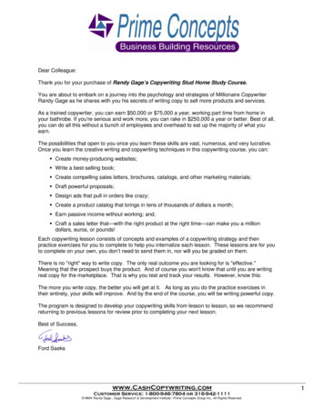
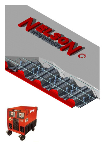
The Nelson SystemNelson Stud Welding is the world‘s leading producer of stud welding fasteners and equipment. Weinvented the stud welding process and have spread its acceptance to a wide variety of end users.Fastening with the Nelson System is quick, reliable and economical. It is a proven and tested methodthat successfully meets stringent fastening, material and welding codes. It has received approvalsfrom recognised design agencies, code bodies and industrial standard organisations.In the construction industry, Nelson pioneered the use of stud welded shear connectors andPunching Shear Resistor Studs.The ProcessElectric-Arc stud welding is the most common process and is utilized whenever metal is fabricated. Itis used to best advantage when the base plate is heavy enough to support the full strength of thewelded studs, but is sometimes used with lighter gauge material.The Stud is held in the welding gun with the end of the stud placed against the work. The cycle isstarted by depressing the trigger button start switch. The stud is then automatically retracted fromthe work piece to establish an arc. The arc continues for predetermined period of time until portionsof the stud and the base plate have been melted. Then, the welding gun automatically plunges thestud into the molten pool of metal and holds it there under spring pressure. At the same time, thewelding current is stopped and, when the molten metal solidifies, the weld is completed and thewelding gun is removed from the stud.The molten metal is held in place by a ceramic ferrule which also serves to shield the arc. The weldmetal is deoxidised by a flux in the weld end of the stud. This results in a dense, strong weld whichwill develop the full strength of the stud and base plate. The weld cycle depends on the diameter ofthe fastener and materials being joined and varies in time from 1/10 to 1-1/2 seconds. Weldingcurrents range from 250 to 3000 amps.3
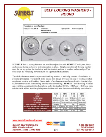
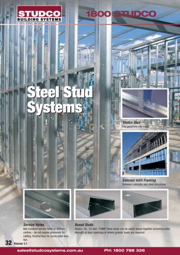
Welding Thru deckThe best welding results are achieved through adherence to recommended job-siteprocedures and conditions. Factors such as painted beam flanges, water, deck fit-up to thebeam, and inadequate power can seriously hamper satisfactory welding.Here are some important site requirements:Top flanges of beams must be unpainted (or at least a strip where the studs areto be welded).Remember if fire protection coating is applied to the rest of the beam (top uncoated)prior to stud welding, that touch up may be required after the studs have beenwelded. (The heat from stud welding may activate the fire protection)The beams should be free of heavy rust and mill scaleThe beams should be free of dirt, sand and other materialsGalvanised beams will need to be ground back to remove the galvanisingWater on the deck, or between the beam and deck must be removed before weldingGun setup for weld-thru deck application4
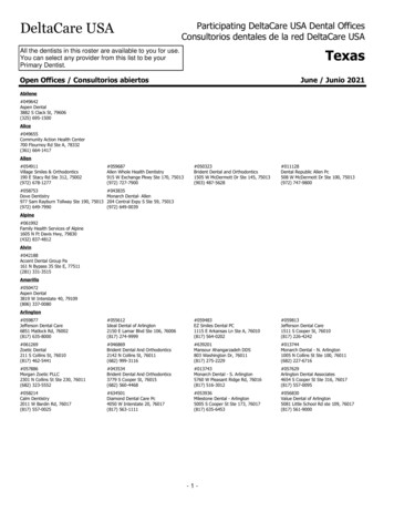
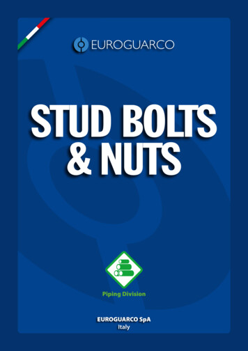
Shear ConnectorsNelson headed shear connectors deliver code specified shear strength values as used incomposite construction, securing concrete to steel structural components. Nelson shearconnectors meet requirements of the following codes:AS/NZS 1554.2 Structural steel welding Part 2: Stud Welding (steel studs to steel)AWS D1.1 Structural Welding Code – SteelAWS D1.6 Structural Welding Code – Stainless SteelAWS D1.5 Structural Welding Code / AASHTO Standard Specification for Highway BridgesCanadian Standards Association W59 – Welded Steel ConstructionAISC Manual of Steel Construction – Allowable Stress DesignAISC Manual of Steel Construction – Load & Resistance Factor DesignSee also: ICC-ES Evaluation Report ESR-2856 Nelson Shear Connector StudsShear connectors are typically used in composite steel construction for holding concrete slabs tosteel members to resist shear forces and increase shear loading capacity in steel buildings, bridges,columns caissons, containment liners, etc. They also act as embedment anchors on miscellaneousembedded plates, frames, angles, strip plates, attachments and connections.Shear Studs held in ease note that limited stocks are held on some sizes.Other sizes may be available, so please contact us.5AHBurnoff82548324103251035513416
Short form specificationTo ensure that certified products are used, the following specification is suggested. “Headed anchorsshall be Nelson Shear Studs, flux filled welding to plates as shown on drawings. Studs shall be madefrom cold drawn steel Grades to I C -1010 through C – 1020 per ASTM A-108 and shall be welded permanufactures recommendation”Physical Properties of Shear ConnectorsDiameterM13M16M19M22As Area of stud shankfs Ultimate strength (tensile):M13, M16, M19, and M22fy Yield strengthElongationReduction AreaAsNominalArea mm2126.7198.0285.0388.0420 Mpa min345 Mpa min20%50% min6As fyYieldKg (min)4,4456,96310,02413,630As fsTensileKg (min)5,3348,35512,02916,356Cold Finished low carbon steelC0.23 maxMn0.90 maxP0.04 MaxS0.05 max
Tension capacityThe following data is presented as guideline as only and are based on embeddedstuds and adequate spacing for full capacity development. Appropriate safetyfactors should be applied based on actual use.Le (3)Ultimate tensilestrength of anchor (4)f'c20.7MPAf'c 27.6MPAf'c 34.5MPAf'c20.7MPAf'c 27.6MPAf'c 34.5MPAf'c20.7MPAf'c 27.6MPAf'c 3DiameterHead diameterFactored tension Capacity Vb (kN) (5)Normal WeightStandard light weightAll light weightConcrete (6)concrete (7)concrete (8)Length after weld (2)Length before weld (1)Shear Stud tension capacity in concreteNotes:(1.) Stock anchor size.(2.) A.W. Length overall after welding.(3.) Le Length of embedment under head of anchor. Ignores thickness ofan embedment plate which will increase Le.(4.) φNs 0.75Asfs(5.) φNb 0.70xλx24 (ƒ'c)Leexp1.5, where φNb φNs, φNs governs as φNn. Assumes no supplemental reinforcement. Pullout and side-face blowoutstrengths not considered.(6.) NWT normal- weight concrete (λ 1.0).(7.) SLWT sand lightweight concrete (λ 0.85).(8.) ALWT All lightweight concrete (λ 0.75).7
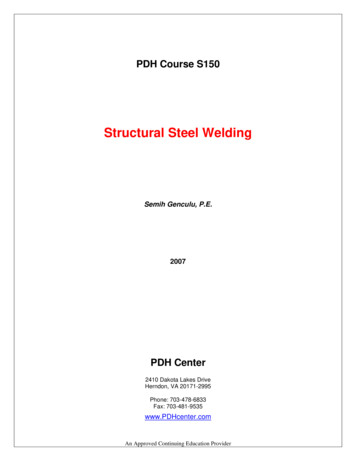
Shear capacityHeaded shear studs embedded in concrete with an embedment length more than fourtimes their diameter are capable of developing full shear capacity. Spacing is not assensitive in shear as in tension. Spacing four times diameter between studs in planeperpendicular to the shear force and six times diameter in the direction of the shearforce is generally adequate to develop full stud capacity. Free edges in the direction ofthe shear force and some spacing restrictions along a free edge apply. Use proper safetyfactors and edge reinforcement.An upper bound limit for headed studs as approached at 0.9 As fs when concrete strength exceeds35MpaHeaded studs used as inserts have different values than those employed in composite design. Forshear capacity of studs in composite design with or without metal deck see appropriate code andcommentary.Stud Shear Capacity in 19.521.121.821.8f'c 20.7MPAf'c 20.7MPAf'c 34.5 MPA18.221.323.3f'c 27.6 MPA15.818.520.2f'c 34.5 MPA36.936.936.9f'c 27.6 MPA3.47.411.4f'c 34.5 MPAFactored steel shearstrength (kN) (3)50100150f'c 27.6 MPAH/Ds (no. of diameters)54105156f'c 20.7MPALength after weld (2)M13M13M13DiameterLength before weld (1)Factored Shear Breakout Capacity Vb (kN) (4)(5)Normal Weight Concrete Standard light-weight concrete All light weight concreteNotes:(1.) Stock anchor size.(2.) A.W. Length overall after welding.(3.) φVs 0.65Asfs(4.) φVb 0.70xλx7*(Le/Da)- exp0.2* (Da)* (ƒ'c)*(edge distance-exp1.5), whereLe/Da 8, alternately (if less) φVb 0.70xλx9 (ƒ'c)*(edge distance-exp1.5). Where8
φVb φVs, φVs governs as φVn. Assumes no supplemental reinforcement. Pryoutstrength not considered.(5.) A six-inches edge distance perpendicular to load is assumed.(6.) NWT normal- weight concrete (λ 1.0).(7.) SLWT sand lightweight concrete (λ 0.85).(8.) ALWT All lightweight concrete (λ 0.75).9
AWS D1.1 Structural Welding Code – Steel AWS D1.6 Structural Welding Code – Stainless Steel AWS D1.5 Structural Welding Code / AASHTO Standard Specification for Highway Bridges Canadian Standards Association W59 – Welded Steel Construction AISC Manual of Steel Construction – Allowable Stress Design AISC Manual of Steel Construction – Load & Resistance Factor Design See also: ICC