Transcription
FLASHSTACK MINICONVERGED INFRASTRUCTUREDesign Guide for Microsoft Applications with Hyper-VJanuary 2017
TABLE OF CONTENTSEXECUTIVE OVERVIEW . 3GOALS AND OBJECTIVES . 3AUDIENCE . 4DESIGN PRINCIPLES . 4FLASHSTACK MINI – INTRODUCTION . 5FLASHSTACK MINI FOR MICROSOFT APPLICATIONCONSOLIDATION – DESIGN OVERVIEW . 7SIMPLIFIED DEPLOYMENT FOR CONSOLIDATEDMICROSOFT SOLUTIONS ON FLASHSTACK MINI . 8LOGICAL INFRASTRUCTURE ARCHITECTURE . 8CONFIGURATION . 10SETTING UP UCS SERVICE PROFILE . 10DEPLOY WINDOWS SERVER 2012 R2 (SAN BOOT) . 16DEPLOYING WINDOWS SERVER FAILOVER CLUSTERS . 21SETTING UP MICROSOFT SYSTEM CENTER VIRTUALMACHINE MANAGER (SCVMM) 2012 R2 . 22CONFIGURING CONTINUOUSLY AVAILABLE FILE SHARES . 29PERFORMANCE BENCHMARKING . 33MICROSOFT WINDOWS 10 BOOT STORM . 33SYNCHRONOUS BOOT . 33ASYNCHRONOUS BOOT . 34MICROSOFT SQL SERVER 2014 OLTP DSS WORKLOADS . 36ONLINE TRANSACTION PROCESSING (OLTP) . 36DECISION SUPPORT SYSTEM (DSS) . 36MICROSOFT EXCHANGE SERVER WORKLOAD. 37ALL WORKLOADS COMBINED . 43DATA REDUCTION . 44CONCLUSION . 45 2017 Pure Storage, Inc. 1
APPENDIX 1: PURE STORAGE COMPONENTS IN FLASHSTACK . 46FLASHARRAY//M . 46PURITY OPERATING ENVIRONMENT . 47PURE1 – COMPONENT FEATURES . 48APPENDIX 2: CISCO COMPONENTS IN FLASHSTACK MINI . 48CISCO UCS 5108 CHASSIS . 50CISCO UCS 6324 FABRIC INTERCONNECT . 50CISCO UCS B200-M4 SERVERS . 51 2017 Pure Storage, Inc. 2
EXECUTIVE OVERVIEWFlashStack Mini from Pure Storage extends the FlashStack converged infrastructureplatform into a smaller, more economical form factor designed for consolidated workloadsand private cloud deployments. FlashStack Mini is built from market leading componentsfrom Cisco and Pure Storage. FlashStack Mini integrates Cisco’s extremely flexible andexpandable Unified Computing System (UCS ) platform to offer network and computecapabilities and Pure Storage FlashArray//M as the Smart Storage foundation. FlashStackMini is delivered via skilled joint Cisco and Pure Storage reseller partners who providethe guidance, services, and experience necessary to help you deploy FlashStack Miniquickly and with confidence. Single-number unified support for FlashStack (includingsystems and software) is provided directly by Cisco or by FlashStack Authorized Support.FlashStack Mini is sized to meet the needs of smaller IT deployments such as those ofsmall- to medium-sized organizations or for larger enterprises who want the power ofFlashStack for their remote or branch offices.Traditional models for IT delivery consist of infrastructure silos leading to low utilizationand high labor costs. Each infrastructure appliance has a standalone managementinterface and requires expensive specialized training. Organizations are constantlychallenged to provide a robust, predictable, and dependable enviroment in the backdropof ever-increasing volume of data, users, and operations. Given this, the deploymentof data center infrastructure can be complex, time consuming, and costly. It is thegoal of FlashStack (including FlashStack Mini) to provide the reliable, scalable, easyto-manage, and high performance platform for consolidated workloads and privatecloud environments.This document describes a reference architecture for deploying consolidated Microsoft workloads on a FlashStack Mini Converged Infrastructure with Microsoft Windows Server Hyper-V . The goal of this document is to showcase the ease of deploying aconsolidated Microsoft applications environment with Microsoft Windows 10 desktops,multiple Microsoft SQL Server 2014 instances, Microsoft Exchange 2016, MicrosoftSharePoint 2016, and home directories using SMB on the FlashStack Mini. Managementof the environment is handled using Microsoft System Center Virtual Machine Manager2012 R2 and templates as the virtual machine building blocks.Several building blocks deployed to showcase online transaction processing (OLTP), datawarehouse (DSS), messaging, and collaboration workloads will illustrate predictable outof-the-box performance without over-subscribing CPU or memory resources. In addition,we highlight the benefits of FlashStack Mini, including data reduction and low latencythat directly impacts the user experience and provides customers a smart, efficient,and Evergreen storage foundation for their large-scale Microsoft applicationdeployment projects.GOALS AND OBJECTIVESThe goal of this document is to showcase the scalability and the resilience of FlashStackMini when tier-1 application workloads such as desktop virtualization, databases,messaging, and collaboration are run simultaneously and at high load. The test datawill show consistent sub-millisecond response times when multiple workloads are in 2017 Pure Storage, Inc. 3
simultaneous operation. Pure Storage has validated the reference architecture within itslab: this document presents the hardware and software configuration, the test workloadconfiguration, and testing results, and further offers implementation and sizing guidancefor a mixed workload. This document will show the following: Microsoft SharePoint – Leveraging pass-through disks, Microsoft SharePointworkload simulated hundreds of active users, with multiple requests from differentclients. SQL Server OLTP – This tests all components of the server and storage subsystemsby stressing the physical I/O layer of SQL Server through random Read/Write I/O,without being limited to a specific load-generating application. SQL Server DSS – A DSS workload using a 500GB dataset is simulated usingHammerDB, an industry-standard, open source database load testing andbenchmarking tool. This simulates hundreds of users logged in at the same timeand loading the SQL Server database with thousands of simultaneous queries.This comprises both database updates and read-only queries. Microsoft Exchange, 300 mailboxes – Microsoft Exchange Jetstress workloadreplicates the storage activity of typical e-mail users. Jetstress simulates theExchange database and log file loads produced by a specified number of users. Windows 10 Remote Desktops – 300 Windows 10 desktop virtual machines runningwith Visual Studio 2015 and Office 2016. Server Message Block (SMB) – High-Availability file shares using Windows ServerFile and Storage Services. Domain User Home Directories – Home directories for individual user storage usingWindows Server File and Storage Services.AUDIENCEThe target audience for this document consists of IT admins, architects, and applicationowners such as Exchange admins, SharePoint admins, and SQL DBAs. This is also usefulfor storage and virtualization administrators, data center architects, and field engineerswho want to implement Microsoft HyperV-based virtualized solutions, particularly privatecloud systems. A working knowledge of Microsoft System Center, Microsoft Hyper-V,Microsoft SQL Server, server, storage, networks, and data center design is assumedbut is not a prerequisite to read this document.DESIGN PRINCIPLESThe guiding principles for implementing this design are: Availability – Create a design that is resilient and not prone to failure of a singlecomponent. For example, we include best practices to enforce multiple paths tostorage, multiple NICs for connectivity, and high availability using System CenterVirtual Machine Manager (VMM) 2012 R2 with Windows Server Failover Clusteringand Hyper-V. 2017 Pure Storage, Inc. 4
Performance – Make sure that the design ensures databases respond to users andapplications in a timely manner. All best practices used for Microsoft SQL Server arefrom the Pure Storage SQL Server Best Practices guide. Simplified and Repeatable Provisioning – Create virtual machine templatesthat provide a building block for Microsoft SQL Server and Windows 10 desktopdeployments. Consolidation – Take advantage of technologies from Cisco and Pure Storage tohelp virtualize and consolidate workloads from multiple application workloads.FLASHSTACK MINI –INTRODUCTIONFlashStack – built with market leading components from Cisco and Pure Storage –is an ideal fit for infrastructure requirements for small- to medium-sized IT environments.FlashStack Mini extends the FlashStack solution range by leveraging the smaller formfactor Cisco “UCS Mini” which combines fabric extenders and fabric interconnects intothe Cisco UCS chassis. With storage, compute, network, and virtualization capabilitiesintegrated in an easy-to-deploy, compact form factor, FlashStack Mini provides acomprehensive solution that can scale up, without disruption, based on business needs.FlashStack Mini offers a set of pre-validated solutions that can be deployed seamlessly. Storage – Pure Storage FlashArray//M brings Smart Storage to businesses of everysize and provides all-flash storage in a modular, stateless architecture, enablingnon-disruptive upgrades as dictated by business needs. FlashArray//M leveragesa chassis-based design with customizable modules, enabling both capacity andperformance to be independently improved over time. Compute and Network – The compute and networking component, Cisco’s UnifiedCommunication Manager (UCS) Mini solution delivers servers, storage, and 10 Gigabitnetworking in an easy-to-deploy, compact form factor. Cisco UCS Mini reduces TCO(total cost of ownership) by consolidating management modules into the chassis,making the chassis stateless, and by reducing the number of network interface cards(NICs), host bus adapters (HBAs), switches, and cables needed. Virtualization – With support for multiple hypervisors, FlashStack Mini provides arobust, production-proven, high-performance solution for virtualized environments.It enables multiple virtual machines to share hardware resources with performancethat can match (and in some cases exceed) native throughput.FlashStack Mini offers the following advantages: Small Form Factor, Mighty Performance – FlashStack Mini provides all-flashperformance, integrated compute and networking, and no-compromise enterprisecapabilities in a small, efficient 9U form factor. 2017 Pure Storage, Inc. 5
Reduced Complexity and Cost – Fully tested, validated, and documented blueprintfacilitates rapid and repeatable deployment. Simplified deployment translates to lowoperational upkeep and accelerated time to value. Consolidate Multiple Workloads – Allows for consolidation of common applicationssuch as server and desktop virtualization, email and business applications on aneasy to use infrastructure solution. Consolidation of operations reduces server andstorage requirements and eliminates IT infrastructure silos. Private Cloud Foundation – Enables virtualization, consolidation, automation, andself-service of IT infrastructure that improves IT and organizational agility.Please see appendices to this document for a detailed overview of Cisco UCS,Cisco Nexus, Pure Storage FlashArray//M, and Microsoft components used in thisdesign guide. 2017 Pure Storage, Inc. 6
FLASHSTACK MINI FORMICROSOFT APPLICATIONCONSOLIDATION – DESIGNOVERVIEWAs IT business needs grow, increased use of server and desktop virtualization againsta backdrop of higher data management is a reality. When virtualization is leveragedto consolidate workloads, infrastructure efficiency is at its peak performance, withbetter resource utilization. In this Microsoft workload consolidation solution testing,the following critical applications were consolidated on a single FlashArray//M: MicrosoftExchange Server 2016, Microsoft SharePoint Foundation 2016, Microsoft SQL Server2014, and Windows 10 remote desktops.The use cases in the testing scenarios will demonstrate the following: Simplified deployment and workload consolidation with FlashStack MiniConverged Infrastructure (CI) Simplified day to day management, infrastructure availability, and elasticity withFlashStack Mini CI Secured infrastructure Ultimate performance for mixed workloads Data reduction efficiencyThe business advantages of the core technologies used in this reference architectureare described below: Provides high availability for all virtual machines at a low cost (compared topurchasing an HA solution on a per-machine basis). The use of System CenterVirtual Machine Manager (VMM) 2012 R2 and Windows Server Failover Clusteringfrom Windows Server 2012 R2 provides a high-availability solution for all virtualmachines with shared storage using Clustered Shared Volumes (CSV). Ability to setup this solution using Windows PowerShell with the new Pure StoragePowerShell SDK and support via cmdlets for Windows Server Failover Clustering,System Center, Hyper-V and SQL Server, provides a tremendous automationframework for repeatable and rapid deployments.Five common, mission-critical applications were deployed: Virtualization – Windows Server 2012 R2 (Hyper-V) Messaging – Microsoft Exchange Server 2016 Collaboration – Microsoft SharePoint Foundation 2016 Database Services – Microsoft SQL Server 2014 Desktop Services – Windows 10 2017 Pure Storage, Inc. 7
SIMPLIFIED DEPLOYMENT FORCONSOLIDATED MICROSOFTSOLUTIONS ON FLASHSTACK MINIIn this section, we will learn more about the high-level topology of the FlashStack Minireference architecture. FlashStack comprises the following hardware and softwarecomponents:HARDWARE Compute – Cisco UCS Mini [Cisco UCS B200 M4 Blade Server Cisco UCS 5108Blade Server Chassis] Network – Cisco UCS Fabric Interconnect 6324 for external and internal connectivityof IP and FC networks. Storage – Pure Storage FlashArray//MSOFTWARE Cisco UCS Manager Cisco UCS Firmware (version 3.1.1E) Microsoft Windows Server 2012 R2 (Hyper-V) Microsoft SQL Server 2014 Microsoft SharePoint Foundation 2016 Microsoft Exchange Server 2016 Microsoft System Center Virtual Machine Manager 2012 R2 (3.2.8228.0, Rollup 11) Pure Storage Web Management interface Pure Storage PowerShell SDKLOGICAL INFRASTRUCTURE ARCHITECTUREThe FlashStack Mini solution comprises a set of hardware and software for yourvirtualized environment. The following table shows some of the nMicrosoft Windows Server 2012 R2 (Hyper-V)ManagementSystem Center Virtual Machine Manager (VMM)2012 R2 2017 Pure Storage, Inc. 8
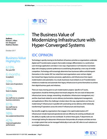
Compute and Network Up to 8 B240M4 blades in 1 Chassis Intel Xeon Processors E5-2600 Cisco UCS 5108 Chassis Cisco UCS Manager v3.1 Cisco UCS 6324 Fabric Interconnects Cisco UCS Virtual Interface Card (VIC) 1340 Up to 36 CPU processors, 1.5TB of memoryStoragePure Storage FlashArray//MTable 1: FlashStack Mini ConfigurationIn the FlashStack Mini physical architecture diagram below, Fabric Interconnect (FI) isembedded in the Cisco UCS chassis. The 1GB Ethernet link connects the managementports of FIs to the port of the ethernet switch to manage the core network. The 8GB FibreChannel links that are used to maintain data storage establishes a connection betweenUCS Mini and Pure Storage FlashArray//M ports using the Fibre Channel protocol (FC).The 10GB Ethernet link transmits frames between the UCS mini chassis ports using theEthernet protocol that can support high-speed, low-latency requirements.Figure 1: FlashStack Mini Wiring Diagram 2017 Pure Storage, Inc. 9
CONFIGURATIONThis section explains the detailed configuration of each FlashStack Mini component inorder to produce the desired results. The following table enlists the components used inthis test rray//MCompute and NetworkingCisco UCS MiniManagementMicrosoft System Center Virtual Machine Manager(VMM) 2012 R2HypervisorMicrosoft Windows Server 2012 R2 (Hyper-V)Operating SystemMicrosoft Windows Server 2012 R2Database applicationMicrosoft SQL Server 2014Table 2. FlashStack Mini CI componentsIn our test setup, Microsoft Hyper-V virtualized infrastructure was deployed on 6 CiscoUCS B200 M4 blade servers, each leveraging a 12-core, 2.3 GHz processor with 256GBof RAM. Service profiles for all servers were created using a service profile template withvHBA templates and the Windows adapter policy was selected for both. Boot-from-SANfunctionality was configured by utilizing the private volume feature of the Purity OperatingEnvironment.SETTING UP UCS SERVICE PROFILECREATE MAC POOLS1. In Cisco UCS Manager, click the LAN tab in the navigation pane.2. Select Pools root.3. Right-click MAC Pools under the root organization.4. Select Create MAC Pool to create the MAC address pool. From Cisco UCS Manager,click the LAN tab in the navigation pane.CREATE WWPN POOLS1. In Cisco UCS Manager, click the SAN tab in the navigation pane.2. Select Pools root.3. Right-click WWPN Pools.4. Select Create WWPN Pool. 2017 Pure Storage, Inc. 10
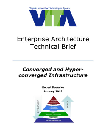
CREATE UUID SUFFIX POOL1. In Cisco UCS Manager, click the Servers tab in the navigation pane.2. Select Pools root.3. Right-click UUID Suffix Pools.4. Select Create UUID Suffix Pool.CREATE VLANS1. In Cisco UCS Manager, click the LAN tab in the navigation pane.2. Select LAN LAN Cloud.3. Right-click VLANs.4. Select Create VLANs.5. Enter the name for VLAN to be used for management traffic.6. Retain the Common/Global option selected for the scope of the VLAN.7. Enter vlan id as the ID of the management VLAN.8. Retain the Sharing Type as None.Figure 2. Cisco UCS Manager Create VLANsCREATE VSANS1. In Cisco UCS Manager, click the SAN tab in the navigation pane.2. Expand the SAN SAN Cloud tree.3. Right-click VSANs.4. Select Create VSAN. 2017 Pure Storage, Inc. 11
5. Enter the name for the VSAN for Fabric A.6. For FC Zoning, retain the Disabled option selected.7. Select Fabric A.8. Enter vsan A id as the VSAN ID for Fabric A.Figure 3. Cisco UCS Manager Create Storage VSAN9. Click OK, and then click OK again to create the VSAN.10. Right-click VSANs.11. Select Create VSAN.12. Enter the name for the VSAN for Fabric B.13. For FC Zoning, retain the Disabled option selected.14. Select Fabric B.15. Enter vsan B id as the VSAN ID for Fabric B.CREATE BOOT POLICIES1. In Cisco UCS Manager, in the navigation pane, click the Servers tab.2. Select Policies root.3. Right-click Boot Policies, and select Create Boot Policy.4. Enter the name for the boot policy. Additionally, you can enter a descriptionfor the boot policy; this is optional.Do not select the Reboot on Boot Order Change checkbox. 2017 Pure Storage, Inc. 12
Figure 4. Cisco UCS Manager Create Boot Policy5. Click OK to create the boot policy.Figure 5. CIsco UCS Manager Create SAN Boot Policy 2017 Pure Storage, Inc. 13
CREATE SERVICE PROFILES1. In Cisco UCS Manager, in the navigation pane, click the Servers tab.2. Select Service Profile root.3. Right-click root, and select Create Service Profile Export to open theCreate Service Profile Export wizard.4. Identify the Service Profile.5. Enter the name for the service profile.6. Under UUID, select the UUID Pool.7. Click Next.Figure 6. Cisco UCS Manager Service Profile TemplateCONFIGURE NETWORKING OPTIONS1. Retain the default setting for Dynamic vNIC Connection Policy.2. Select the Expert option to configure the LAN connectivity.3. Click the upper Add button to add a vNIC1.4. In the Create vNIC dialog box, enter the name for vNIC.5. Under MAC, select the Mac Pool.6. In the Fabric ID, select the Enable Failover.7. Select the Management VLAN.8. In the Adapter Policy list, select Windows. 2017 Pure Storage, Inc. 14
Figure 7. UCS Service Proflle Networking configuration 2017 Pure Storage, Inc. 15
Figure 8. Service Profile vNIC creation9. Click OK, and then click the Add button to add a second vNIC (eg. vNIC2).Repeat the steps in Configure Network Options.DEPLOY WINDOWS SERVER 2012 R2 (SAN BOOT)After creating the Cisco UCS service profiles they must be associated to available servers.1. From Cisco UCS Manager, from root, right click the service profile name from Step 8 and click Associate with Server Pool. 2017 Pure Storage, Inc. 16
Figure 9. Associate Service Profile to Server Pool2. From the equipment console, right click the required server, and selectKVM Console.Figure 10. Accessing the KVM Console of the Server 2017 Pure Storage, Inc. 17
3. Ensure that the Fibre Channel boot LUNs are discovered and displayed onthe BIOS screen.4. Launch Windows Server 2012 R2 ISO; click Next.5. Install Cisco vNIC driver pack from ISO image repository from CD/DVD.Figure 11. Fibre Channel boot connectivityFigure 12. CIsco UCS Boot Drivers6. Upon successful completion of Windows Server 2012 R2 installation and reboots,select the Local Server within Server Manager Add Roles and Features Wizard.From the Features section enable Multipath I/O and Failover Clustering. 2017 Pure Storage, Inc. 18
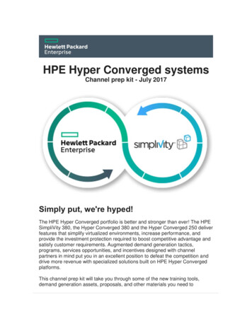
Figure 13. Add Roles and Features Wizard7. Click Next and complete the installation process. This will not require a reboot.8. Open a Windows PowerShell console and enter:New-MSDSMSupportedHW -VendorId 'PURE' -ProductId 'FlashArray'.9. From Server Manager, click Tools MPIO. The MPIO Properties screen appears.From the MPIO Devices tab, ensure that the Pure Storage FlashArray is discovered.Figure 14. Windows Server 2012 R2 MPIO Properties 2017 Pure Storage, Inc. 19
10. Verify multipath is configured correctly by starting an elevated command promptand entering the following:mpclaim –s –dThe MPIO disk is displayed in the result if the configuration was successful.Figure 15. Checking mulipathing with mpclaimFigure 15 shows that all MPIO Disks are using the Load Balancing policy of LeastQueue Depth (LQD). This is documented as part of the Pure Storage WindowsServer Best Practices located at https://support.purestorage.com.11. From the Pure Storage FlashArray//M10 Web Management interface, in theSystems tab, from the Host Connections option, ensure that multipath is configuredas required.Figure 16. FlashArray host redundant connections 2017 Pure Storage, Inc. 20
DEPLOYING WINDOWS SERVER FAILOVER CLUSTERSCREATING FAILOVER CLUSTERING FEATURE1. Start Server Manager.2. On the Manage menu, click Add Roles and Features.3. On the Before you begin page, click Next.4. On the Select installation type page, click Role-based or feature-based installation,and then click Next.5. On the Select destination server page, click the server where you want to installthe feature, and then click Next.6. On the Select server roles page, click Next.7. On the Select features page, select the Failover Clustering check box.8. To install the failover cluster management tools, click Add Features, and thenclick Next.9. On the Confirm installation selections page, click Install.10. When the installation is completed, click Close.11. Repeat this procedure on every server that you want to add as a failovercluster node.VALIDATE THE CLUSTER CONFIGURATION1. Before you create a failover cluster, you must validate whether the nodes havebeen configured as required.2. To do this on a server, start Server Manager, and then on the Tools menu,click Failover Cluster Manager Create Cluster Wizard.Figure 17. Create Cluster Wizard 2017 Pure Storage, Inc. 21
3. If the Select Servers page appears, in the Enter server name textbox, enter theNetBIOS name or the fully qualified domain name (FQDN) of a server to participatein the failover cluster, then click Add.4. From the Validate Warning page, click Run all tests (recommended), and thenclick Next.Do not select the Reboot on Boot Order Change checkbox.5. On the Access Point for Administering the Cluster page, In the Cluster Name box,enter a name for the cluster.6. Click Next and Finish.Once you have completed creating the clusters, verify that the storage, nodes, disk, andnetwork are up and running:Figure 18. Windows Server Failover ClusterSETTING UP MICROSOFT SYSTEM CENTER VIRTUALMACHINE MANAGER (SCVMM) 2012 R2This section explains the procedure to set up Microsoft System Center Virtual MachineManager (SCVMM) 2012 R2. To complete this procedure, you must have a deployedinstance of Microsoft System Center Virtual Machine Manager 2012 R2 and a PureStorage FlashArray//M or FlashArray FA-400 series running Purity 4.6 or greater. 2017 Pure Storage, Inc. 22
This solution uses SCVMM to manage the Windows Server Failover Cluster and theHyper-V virtual machines, shown in Figure 19. SCVMM leverages the Pure Storage SMI-SProvider to communicate with the FlashArray to perform provisioning and capacitymanagement, shown in Figure 20.Figure 19. Microsoft System Center Virtual Machine Manager 2012 R2 2017 Pure Storage, Inc. 23
Figure 20. Pure Storage SMI-S Provider added to SCVMM1. Enable the SMI-S services such as Service Location Protocol and SMI-S Provider.Log on to FlashArray//M10, and from Systems tab, click SMI-S. Click Enable, theSMI-S services are disabled by default.Figure 21. Enable SMI-S on the Pure Storage FlashArray 2017 Pure Storage, Inc. 24
2. After the services are enabled, log on to the physical or virtual host that hasMicrosoft System Center Virtual Machine Manager 2012 R2 (SCVMM) deployed.Figure 22. SCVMM log in dialog3. After you are logged in, from the Add Resources option, choose Add StorageDevices Wizard.Figure 23. Adding a Storage Device in SCVMM4. The Add Storage Devices wizard opens. Perform the following steps:a) From the Select Storage Provider Type page, select SAN and NAS devicesdiscovered and managed by a SMI-S Provider. Click Next.b) From the Specify Discovery Scope page, select the following:i. Protocol – SMI-S CIMXML 2017 Pure Storage, Inc. 25
ii. Provider IP address or FQDN – Use either an IP address or Fully QualifiedDomain Name (FQDN) for the FlashArrayiii. TCP/IP Port – Check the Use Secure Sockets Layer (SSL) connection optionbelow, and this TCP\IP port value defaults to 5989.iv. Run As Account – Click Browse and select an account to perform FlashArrayweb management. To create a new account, click Browse, and click CreateRun As account.v. Click OK, and then Next to start the discovery and import task.c) Click Next.d) From the Gather Information page, view the discovery process. Once complete,click Next.e) From the Select Storage Devices page, check that the FlashArray that has beendiscovered. Using the Create Classification option, assign a classification thatdescribes the capabilities of the selected storage pool. For example: Tier1, SSD,Gold, Silver, Bronze.f) Click Next.g) After the discovery and import process is complete, confirm the settings and clickFinish.h) Verify the details of FlashArray as displayed in the Jobs view:Figure 24. Add-SCStorageProvider operation 2017 Pure Storage, Inc. 26
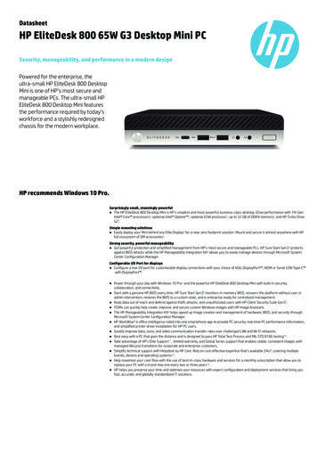
Figure 25. Set-SCStorageArray operation5. We will now create a Logical Unit (LUN) using the SMI-S Provider. The first releaseof the SMI-S Provider supports the Provisioning and Capacity management profile.From the Home tab, click Create Logical Units.Figure 26. Create Logical Unit (LUN)6. Enter a name, description, and size. In the setup below, we have the Create thinstorage logical unit with capacity committed on demand selected. Click OK. 2017 Pure Storage, Inc. 27
Figure 27. Create Logical Unit (LUN) detailsOnce the LUN has been created, it will be displayed in the Classi
from Cisco and Pure Storage. FlashStack Mini integrates Cisco's extremely flexible and expandable Unified Computing System (UCS ) platform to offer network and compute capabilities and Pure Storage FlashArray//M as the Smart Storage foundation. FlashStack Mini is delivered via skilled joint Cisco and Pure Storage reseller partners who provide