Transcription
LECTURE NOTESONELECTRONIC DEVICES AND CIRCUITSB.Tech IIIsemester(Common for ECE/EEE)Dr. P.Ashok Babu, ProfessorMr. V R Seshagiri Rao, ProfessorMr. K.Sudhakar Reddy, AssosciateProfessorMr. B.Naresh, AssosciateProfessorELECTRONICS AND COMMUNICATION ENGINEERINGINSTITUTE OF AERONAUTICAL ENGINEERING(Autonomous)DUNDIGAL, HYDERABAD - 500043
ELECTRONIC DEVICES AND CIRCUITSIII Semester: ECECourse CodeCategoryAEC001FoundationHours / WeekLTP31-CreditsC4Maximum MarksCIASEE Total3070100Contact Classes: 45Tutorial Classes: 15Practical Classes: NilTotal Classes: 60OBJECTIVES:The course should enable the students to:1. Be acquainted with electrical characteristics of ideal and practical diodes under forward and reversebias to analyze and design diode application circuits such as rectifiers and voltage regulators.2. Utilize operational principles of bipolar junction transistors and field effect transistors to deriveappropriate small-signal models and use them for the analysis of basic amplifier circuits.3. Perform DC analysis (algebraically and graphically using current voltage curves with superimposed load line) and design of CB,CE and CC transistor circuits.4. IV. Compare and contrast different biasing and compensation techniquesUNIT-ISEMICONDUCTOR DIODESClasses: 08PN Junction Diode : Theory of PN diode, energy band diagram of PN diode, PN junction as a diode,operation and V-I characteristics , static and dynamic resistances, diode equivalent circuits, diffusionand transition capacitance, diode current equation, temperature dependence of V-I characteristics,Zener diode characteristics ,break down mechanisms in semiconductor diodes, Zener diode as avoltageregulator.UNIT-IISPECIAL PURPOSE ELECTRONIC DEVICES AND RECTIFIERSClasses: 10Special purpose electronic devices: principles of operation and characteristics of silicon controlledrectifier, tunnel diode, varactor diode, photodiode; Half wave rectifier, full wave rectifier, general filterconsideration, harmonic components in a rectifier circuit , Inductor Filter, capacitor filter, L-Sectionfilter, multiple L-C section, RC filter, comparison of filters.UNIT-III TRANSISTORSClasses: 08Bipolar Junction Transistors: Construction of BJT, operation of BJT, minority carrier distributions andcurrent components, configurations, characteristics, BJT specifications; Applications: Amplifier,switch.Field Effect Transistors: Types of FET, FET construction, symbol, principle of operation, V-Icharacteristics, FET parameters, FET as voltage variable resistor, comparison of BJT and FET;MOSFET construction and operation; Uni-Junction Transistor: Symbol, principle of operation,characteristics, applications (UJT as relaxation oscillator).UNIT-IVBIASING AND COMPENSATION TECHNIQUESClasses: 10Need for biasing, BJT operating point, The DC and AC load lines, types of biasing circuits, biasstability, stabilization factors, stabilization against variations in VBE and β; Bias compensationtechniques, thermal runaway, thermal stability, biasing the FET and MOSFET.
UNIT-VClasses: 09BJT AND FET AMPLIFIERSBJT small signal analysis, BJT hybrid model, determination ofcharacteristics, transistor amplifiers analysis using h- parameters; Fcommon source amplifier, FET as common drain amplifier, FEgeneralized FET amplifier .h-parameters from transistorET small signal model, FET asT as common gate amplifier,Text Books:nd1. J. Millman, C.C.Halkias, “Millman‘s Integrated Electronics”, Tata McGraw-Hill, 2 Edition, 2001.2. J. Millman, C.C.Halkias, Satyabrata Jit, ―Millman‘s Electronic Devices and Circuits‖, TataMcGrawHill, 2ndEdition, 1998.th3. David A. Bell, ―Electronic Devices and Circuits‖, Oxford University Press ,5 Edition,2008.Reference Books:st1. Sedha.R.S, “A Text Book of Applied Electronics‖, Sultan Chand Publishers”,1 Edition, 20082. R L. Boylestad, Louis Nashelsky, “Electronic Devices and Circuits‖, PEI/PHI”, 9thedition,2006.Gupta.J.B,nd3. “Electron Devices and Circuits‖, S.K.Kataria & Sons”, 2Edition,2012. Salivahanan, N. SureshKumar,A. Vallavaraj.Web etails/ElectronicDevicesCircuits -electron-devices-by.htmlE-Text And-Circuits(EDC)-by- J-B-Gupta-full-book-pdf
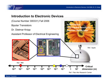
1UNIT 1PN JUNCTION DIODEINTRODUCTONBased on the electrical conductivity all the materials in nature are classified as insulators, semiconductors,and conductors.Insulator: An insulator is a material that offers a very low level (or negligible) of conductivity whenvoltage is applied. Eg: Paper, Mica, glass, quartz. Typical resistivity level of an insulator is of the order of1010 to 1012 Ω-cm. The energy band structure of an insulator is shown in the fig.1.1. Band structure of amaterial defines the band of energy levels that an electron can occupy. Valance band is the range ofelectron energy where the electron remain bended too the atom and do not contribute to the electriccurrent. Conduction bend is the range of electron energies higher than valance band where electrons arefree to accelerate under the influence of external voltage source resulting in the flow of charge.The energy band between the valance band and conduction band is called as forbidden band gap.It is the energy required by an electron to move from balance band to conduction band i.e. the energyrequired for a valance electron to become a free electron.1 eV 1.6 x 10⁻¹⁹ JFor an insulator, as shown in the fig.1.1 there is a large forbidden band gap of greater than 5Ev. Becauseof this large gap there a very few electrons in the CB and hence the conductivity of insulator is poor. Evenan increase in temperature or applied electric field is insufficient to transfer electrons from VB to CB.
2CBCBoForbidden bandgap Eo 6eVEo 6eVVBVBVBInsulatorCBSemiconductorConductorFiG:1.1 Energy band diagrams insulator, semiconductor and conductorConductors: A conductor is a material which supports a generous flow of charge when a voltageis applied across its terminals. i.e. it has very high conductivity. Eg: Copper, Aluminum, Silver,Gold. The resistivity of a conductor is in the order of 10-4 and 10-6 Ω-cm. The Valance andconduction bands overlap (fig1.1) and there is no energy gap for the electrons to move fromvalance band to conduction band. This implies that there are free electrons in CB even atabsolute zero temperature (0K). Therefore at room temperature when electric field is appliedlarge current flows through the conductor.Semiconductor: A semiconductor is a material that has its conductivity somewhere between theinsulator and conductor. The resistivity level is in the range of 10 and 104 Ω-cm. Two of the mostcommonly used are Silicon (Si 14 atomic no.) and germanium (Ge 32 atomic no.). Both have 4valance electrons. The forbidden band gap is in the order of 1eV. For eg., the band gap energyfor Si, Ge and GaAs is 1.21, 0.785 and 1.42 eV, respectively at absolute zero temperature (0K).At 0K and at low temperatures, the valance band electrons do not have sufficient energy to movefrom V to CB. Thus semiconductors act a insulators at 0K. as the temperature increases, a largenumber of valance electrons acquire sufficient energy to leave the VB, cross the forbiddenbandgap and reach CB. These are now free electrons as they can move freely under the influenceof electric field. At room temperature there are sufficient electrons in the CB and hence thesemiconductor is capable of conducting some current at roomtemperature.Inversely related to the conductivity of a material is its resistance to the flow of charge orcurrent. Typical resistivity values for various materials’ are given as follows.
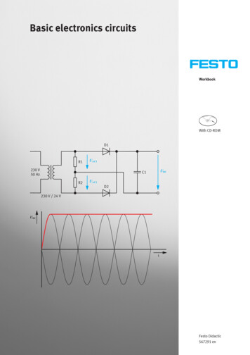
3InsulatorSemiconductorConductor10-6 Ω-cm (Cu)50Ω-cm (Ge)1012Ω-cm(mica)50x103 Ω-cm (Si)Typical resistivity valuesSemiconductorTypesA pure form of semiconductors is called as intrinsic semiconductor. Conduction in intrinsic sc iseither due to thermal excitation or crystal defects. Si and Ge are the two most important semiconductorsused. Other examples include Gallium arsenide GaAs, Indium Antimonide (InSb) etc.Let us consider the structure of Si.A Si atomic no. is 14 and it has 4 valance electrons. These 4electrons are shared by four neighboring atoms in the crystal structure by means of covalent bond. Fig.1.2a shows the crystal structure of Si at absolute zero temperature (0K). Hence a pure SC acts has poorconductivity (due to lack of free electrons) at low or absolute zero temperature.Covalent bondValence electronFig. 1.2a crystal structure of Si at 0K
4At room temperature some of the covalent bonds break up to thermal energy as shown infig 1.2b. The valance electrons that jump into conduction band are called as free electrons thatare available forconduction.Free electronValance electronholeFig. 1.2b crystal structure of Si at roomtemperature0KThe absence of electrons in covalent bond is represented by a small circle usuallyreferred to as hole which is of positive charge. Even a hole serves as carrier of electricity in amanner similar to that of freeelectron.The mechanism by which a hole contributes to conductivity is explained as follows:When a bond is in complete so that a hole exists, it is relatively easy for a valanceelectron in the neighboring atom to leave its covalent bond to fill this hole. An electron movingfrom a bond to fill a hole moves in a direction opposite to that of the electron. This hole, in itsnew position may now be filled by an electron from another covalent bond and the hole willcorrespondingly move one more step in the direction opposite to the motion of electron. Here wehave a mechanism for conduction of electricity which does not involve free electrons. Thisphenomenon is illustrated infig1.3
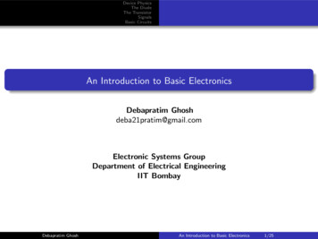
5Electron movementHole movementFig. 1.3aFig. 1.3bFig. 1.3c
6Fig 1.3a show that there is a hole at ion 6.Imagine that an electron from ion 5 moves intothe hole at ion 6 so that the configuration of 1.3b results. If we compare both fig1.3a &fig 1.3b, itappears as if the hole has moved towards the left from ion6 to ion 5. Further if we compare fig1.3b and fig 1.3c, the hole moves from ion5 to ion 4. This discussion indicates the motion ofhole is in a direction opposite to that of motion of electron. Hence we consider holes as physicalentities whose movement constitutes flow ofcurrent.In a pure semiconductor, the number of holes is equal to the number of free electrons.EXTRINSICSEMICONDUCTOR:Intrinsic semiconductor has very limited applications as they conduct very small amountsof current at room temperature. The current conduction capability of intrinsic semiconductor canbe increased significantly by adding a small amounts impurity to the intrinsic semiconductor. Byadding impurities it becomes impure or extrinsic semiconductor. This process of addingimpurities is called as doping. The amount of impurity added is 1 part in 106 atoms.N type semiconductor: If the added impurity is a pentavalent atom then the resultantsemiconductor is called N-type semiconductor. Examples of pentavalent impurities arePhosphorus, Arsenic, Bismuth, Antimony etc.A pentavalent impurity has five valance electrons. Fig 1.3a shows the crystal structure of Ntype semiconductor material where four out of five valance electrons of the impurityatom(antimony) forms covalent bond with the four intrinsic semiconductor atoms. The fifthelectron is loosely bound to the impurity atom. This loosely bound electron can be easilyFifth valance electron of SBCBEcEdDonor energy levelEvVBFig. 1.3a crystal structure of NtypeSCFig. 1.3bEnergy band diagram of Ntype
7excited from the valance band to the conduction band by the application of electric field orincreasing the thermal energy. The energy required to detach the fifth electron form the impurityatom is very small of the order of 0.01ev for Ge and 0.05 eV for Si.The effect of doping creates a discrete energy level called donor energy level in the forbiddenband gap with energy level Ed slightly less than the conduction band (fig 1.3b). The differencebetween the energy levels of the conducting band and the donor energy level is the energyrequired to free the fifth valance electron (0.01 eV for Ge and 0.05 eV for Si). At roomtemperature almost all the fifth electrons from the donor impurity atom are raised to conductionband and hence the number of electrons in the conduction band increases significantly. Thusevery antimony atom contributes to one conduction electron without creating a hole.In the N-type sc the no. of electrons increases and the no. of holes decreases compared tothose available in an intrinsic sc. The reason for decrease in the no. of holes is that the larger no.of electrons present increases the recombination of electrons with holes. Thus current in N typesc is dominated by electrons which are referred to as majority carriers. Holes are the minoritycarriers in N typescP type semiconductor: If the added impurity is a trivalent atom then the resultant semiconductoris called P-type semiconductor. Examples of trivalent impurities are Boron, Gallium , indium etc.The crystal structure of p type sc is shown in the fig1.3c. The three valance electrons of theimpurity (boon) forms three covalent bonds with the neighboring atoms and a vacancy exists inthe fourth bond giving rise to the holes. The hole is ready to accept an electron from theneighboring atoms. Each trivalent atom contributes to one hole generation and thus introduces alarge no. of holes in the valance band. At the same time the no. electrons are decreased comparedto those available in intrinsic sc because of increased recombination due to creation of additionalholes.holeFig. 1.3c crystal structure of P type sc
8Thus in P type sc , holes are majority carriers and electrons are minority carriers. Sinceeach trivalent impurity atoms are capable accepting an electron, these are called as acceptoratoms. The following fig 1.3d shows the pictorial representation of P type schole (majority carrier)Electron (minority carrier)Acceptor atomsFig. 1.3d crystal structure of P type sc The conductivity of N type sc is greater than that of P type sc as the mobility ofelectron is greater than that ofhole. For the same level of doping in N type sc and P type sc, the conductivity of anNtypesc is around twice that of a P typescCONDUCTIVITY OFSEMICONDUCTOR:In a pure sc, the no. of holes is equal to the no. of electrons. Thermal agitation continue toproduce new electron- hole pairs and the electron hole pairs disappear because of recombination.with each electron hole pair created , two charge carrying particles are formed . One is negativewhich is a free electron with mobility µ n . The other is a positive i.e., hole with mobility µ p . Theelectrons and hole move in opppsitte direction in a an electric field E, but since they are ofopposite sign, the current due to each is in the same direction. Hence the total current density Jwithin the intrinsic sc is given byJ Jn Jp q n µn E q p µp E (n µn p µp)qE σ EWhere n no. of electrons / unit volume i.e., concentration of free electronsP no. of holes / unit volume i.e., concentration of holesE applied electric field strength, V/mq charge of electron or hole I n Coulombs
9Hence, σ is the conductivity of sc which is equal to (n µ n p µp)q. he resistivity of sc isreciprocal of conductivity.Ρ 1/ σIt is evident from the above equation that current density with in a sc is directlyproportional to applied electric field E.For pure sc, n p ni where ni intrinsic concentration. The value of ni is given byni 2 AT3 exp (-EGO/KT)therefore, J ni ( µn µp) qEHence conductivity in intrinsic sc is σi ni ( µn µp) qIntrinsic conductivity increases at the rate of 5% per o C for Ge and 7% per o C for Si.Conductivity in extrinsic sc (N Type and P Type):The conductivity of intrinsic sc is given by σi ni ( µn µp) q (n µn p µp)qFor N type , n pTherefore σ q n µnFor P type ,p nThe energy band diagram of p-n junction under open circuitconditions( Expression for pn junction diode barrier potential. ) It is known that the Fermi level in n-type material lies just below the conduction band while inp-type material, it lies just above the valenceband.When p-n junction is formed, the diffusion starts. The changes get adjusted so as toequalizethe Fermi level in the two parts of p-njunction.This is similar to adjustment of water levels in two tanks of unequal level, when connectedeachother.The changes flow from p to n and n to p side till, the Fermi level on two sides get linedup.In n-type semi conductor , EF is close to conduction band Ecn and it is close to valence bandedge EVP onp-side.So the conduction band edge of n-type semiconductor can‟t be at the same level as that of ptype semiconductor.
10 Hence, as shown, the energy band diagram for p-n junction is where a shift in energy levels E0isindicated.
11
121.0.5 Doide current equation When a forward bias (VA 0) is applied, the potential barrier to diffusion across thejunction isreduced– Minority carriers are “injected” into the quasi-neutral regions Dnp 0, Dpn 0 Minority carriers diffuse in the quasi-neutral regions, recombining with majoritycarriers Solve minority-carrier diffusion equations in quasi-neutral regions to obtain excesscarrier distributionsDnp(x,VA),Dpn(x,VA)
13 – boundaryconditions: p side: Dnp(-xp),Dnp(- ) n side: Dpn(xn),Dpn( )Find minority-carrier current densities in quasi-neutral regionsEvaluate Jn at x -xp&Jpat x xn to obtain total current density JJ (VA ) Jn ( xp ,VA ) J p (xn ,VA )Consider the equilibrium (VA 0) carrier concentrations:Consider the equilibrium (VA 0) carrier concentrations:p siden sidep p 0 ( x p ) N Ann0 (xn ) N Dn2 in p0 ( x p ) NAn2pn0 (xn ) iNDIf low-level injection conditions hold in the quasi-neutral regionswhen VA 0, thenpp ( xp ) NAnn (xn ) ND
14The voltage applied to a pn junction falls mostly across the depletionregion (assuming low-level injection in the quasi-neutral regions).We can draw 2 quasi-Fermi levels in the depletion region:p n ie( Ei FP )/ kTn n ie( FN Ei )/ kTpn n2i e( FN FP )/ kTpn n i2eqV / AkTExcess Carrier Concentrations at –xp, xnp siden sidepp ( xp ) NAnn (xn ) NDn 2 e q V /kTAnp ( xp ) ipn (x n ) iANDq V /kT pen0NA n p0 e q V /kTAA n 2 e q V /kT2 np ( xp ) ni qV / kT eNAA 1 n2 pn (xn ) ie N DqVA / kT 1
15 Excess Carrier Distribution (n side) d 2 p pn pnn dx2 D L2p pp From the minority carrier diffusionequation: We have the following boundary conditions: p (x ) p (e qV /kT 1) p ( ) 0Annnno For simplicity, use a new coordinatesystem:NEW: x’’0x’0 p (x') Ae Then, the solution is of theform:n p (x') Aenx '/ Lp1 A ex'/ Lp1 x'/ Lp2Fromthex boundarycondition:Fromthex xnboundarycondition:Therefore x'/Lp, x' 0 pn (x') pno (eqVA/kT 1)eSimilarly, we can derive n(x'') nppo(e qVA/kT 1)e x''/Ln , x'' 0 A e x'/ Lp2
16Total Current Densityp side:n side:d np (x'')J qDnnJ p qDpdx''d pn (x')dx'J Jn x x J p x xpn q qDnnLnDpp0(e qVAkT 1)e x ''LnqVkTpn0 (eLpA 1)e x' Lp Jn x 0 J p x 0Dp qV kT 1) DnJ qn2 i LN L N (epD n AA Ideal Diode EquationqVAkTI I(e 1)0 DpDn I0 Aqni N pDLn N A L2
17 Diode Saturation Current I0 I0 can vary by orders of magnitude,depending on thesemiconductor material and dopant concentrations: Dp Dn I0 Aqn2i L N LNpDnA In an asymmetrically doped (one-sided) pn junction, thetermassociated with the more heavily doped side is negligible: D – If the p side is much more heavily doped, I 0 Aqni 2 L Np D p2 Dn – If the n side is much more heavily doped, I Aqn 0 i LN nA Carrier Concentration Profilesunder ReverseBias Depletion of minority carriers at edges of depletionregion The only current which flows is due to drift of minority carriersacross the junction. This current is fed by diffusion of minoritycarriers toward junction (supplied by thermalgeneration).
18Alternative Derivation of Formula for I0“Depletion approximation”: I0 is the rate at which carriersare thermally generated withinone diffusion length of thedepletionregion:2 n np ni / N A t n n2 p pn /ND n i t p p -LN -xp x -xpxn x xn LP 2 i n 2 / N A i n / N D I 0 qALN qALP n p Under forward bias (VA 0), the potential barrier to carrierdiffusionisreduced ralregions.– The minority-carrier concentrations at the edges of the depletionregionchange with the applied bias V A, by the factore q VA /kT– The excess carrier concentrations in the quasi-neutral regions decay tozero away from the depletion region, due torecombination.Dp (e qV kT 1) DnI qAn2 i LN LN pD n AApn junction diodecurrent onQUANTITATIVE THEORY OF PN JUNCTIONDIODE:PN JUNCTION WITH NO APPLIED VOLTAGE OR OPENCIRCUITCONDITION:In a piece of sc, if one half is doped by p type impurity and the other half is doped by ntype impurity, a PN junction is formed. The plane dividing the two halves or zones is called PNjunction. As shown in the fig the n type material has high concentration of free electrons, while ptype material has high concentration of holes. Therefore at the junction there is a tendency of
19free electrons to diffuse over to the P side and the holes to the N side. This process is calleddiffusion. As the free electrons move across the junction from N type to P type, the donor atomsbecome positively charged. Hence a positive charge is built on the N-side of the junction. Thefree electrons that cross the junction uncover the negative acceptor ions by filing the holes.Therefore a negative charge is developed on the p –side of the junction.This net negative chargeon the p side prevents further diffusion of electrons into the p side. Similarly the net positivecharge on the N side repels the hole crossing from p side to N side. Thus a barrier sis set up nearthe junction which prevents the further movement of charge carriers i.e. electrons and holes. As aconsequence of induced electric field across the depletion layer, an electrostatic potentialdifference is established between P and N regions, which are called the potential barrier, junctionbarrier, diffusion potential or contact potential, Vo. The magnitude of the contact potential Vovaries with doping levels and temperature. Vo is 0.3V for Ge and 0.72 V for Si.The electrostatic field across the junction caused by the positively charged N-Type regiontends to drive the holes away from the junction and negatively charged p type regions tend todrive the electrons away from the junction. The majority holes diffusing out of the P region leavebehind negatively charged acceptor atoms bound to the lattice, thus exposing a negatives pacecharge in a previously neutral region. Similarly electrons diffusing from the N region exposepositively ionized donor atoms and a double space charge builds up at the junction as shown inthe fig. 1.7
20It is noticed that the space charge layers are of opposite sign to the majority carriersdiffusing into them, which tends to reduce the diffusion rate. Thus the double space of the layercauses an electric field to be set up across the junction directed from N to P regions, which is insuch a direction to inhibit the diffusion of majority electrons and holes as illustrated in fig 1.7.The shape of the charge density, ρ, depends upon how diode id doped. Thus the junction regionis depleted of mobile charge carriers. Hence it is called depletion layer, space region, andtransition region. The depletion region is of the order of 0.5µm thick. There are no mobilecarriers in this narrow depletion region. Hence no current flows across the junction and thesystem is in equilibrium. To the left of this depletion layer, the carrier concentration is p N Aandto its right it is n ND.
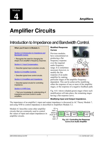
21FORWARD BIASED JUNCTIONDIODEWhen a diode is connected in a Forward Bias condition, a negative voltage is applied to the Ntype material and a positive voltage is applied to the P-type material. If this external voltagebecomes greater than the value of the potential barrier, approx. 0.7 volts for silicon and 0.3 voltsfor germanium, the potential barriers opposition will be overcome and current will start to flow.This is because the negative voltage pushes or repels electrons towards the junction giving themthe energy to cross over and combine with the holes being pushed in the opposite directiontowards the junction by the positive voltage. This results in a characteristics curve of zero current
22flowing up to this voltage point, called the "knee" on the static curves and then a high currentflow through the diode with little increase in the external voltage as shown below.Forward Characteristics Curve for a Junction DiodeThe application of a forward biasing voltage on the junction diode results in the depletion layerbecoming very thin and narrow which represents a low impedance path through the junctionthereby allowing high currents to flow. The point at which this sudden increase in current takesplace is represented on the static I-V characteristics curve above as the "knee" point.Forward Biased Junction Diode showing a Reduction in the Depletion Layer
23This condition represents the low resistance path through the PN junction allowing very largecurrents to flow through the diode with only a small increase in bias voltage. The actual potentialdifference across the junction or diode is kept constant by the action of the depletion layer atapproximately 0.3v for germanium and approximately 0.7v for silicon junction diodes. Since thediode can conduct "infinite" current above this knee point as it effectively becomes a shortcircuit, therefore resistors are used in series with the diode to limit its current flow. Exceeding itsmaximum forward current specification causes the device to dissipate more power in the form ofheat than it was designed for resulting in a very quick failure of the device.1.1.2 PN JUNCTION UNDER REVERSE BIAS CONDITION:A silicon p–n junction in reverse bias.Reverse Biased Junction DiodeWhen a diode is connected in a Reverse Bias condition, a positive voltage is applied to the Ntype material and a negative voltage is applied to the P-type material. The positive voltageapplied to the N-type material attracts electrons towards the positive electrode and away fromthejunction, while the holes in the P-type end are also attracted away from the junction towards thenegative electrode. The net result is that the depletion layer grows wider due to a lack ofelectrons and holes and presents a high impedance path, almost an insulator. The result is that ahigh potential barrier is created thus preventing current from flowing through the semiconductormaterial.Reverse Biased Junction Diode showing an Increase in the Depletion Layer
24This condition represents a high resistance value to the PN junction and practically zero currentflows through the junction diode with an increase in bias voltage. However, a very small leakagecurrent does flow through the junction which can be measured in microamperes, (μA). One finalpoint, if the reverse bias voltage Vr applied to the diode is increased to a sufficiently high enoughvalue, it will cause the PN junction to overheat and fail due to the avalanche effect around thejunction. This may cause the diode to become shorted and will result in the flow of maximumcircuit current, and this shown as a step downward slope in the reverse static characteristicscurve below.Reverse Characteristics Curve for a Junction Diode
25Sometimes this avalanche effect has practical applications in voltage stabilising circuits where aseries limiting resistor is used with the diode to limit this reverse breakdown current to a presetmaximum value thereby producing a fixed voltage output across the diode. These types of diodesare commonly known as Zener Diodes and are discussed in a later tutorial.V-I CHARACTERISTICS AND THEIRTEMPERATUREDEPENDENCE:Diode terminal characteristics equation for diode junction current: vID 0Where VT kT/q;VD diode terminal voltage, VoltsIo temperature-dependent saturation current, µAT absolute temperature of p-n junction, Kk Boltzmann’s constant 1.38x 10 -23J/K)q electron charge 1.6x10⁻¹⁹ C empirical constant, 1 for Ge and 2 for SiTemperature Effects on DiodeI(e vT 1)
26Temperature can have a marked effect on the characteristics of a silicon semiconductor diode asshown in Fig. 1.24. It has been found experimentally that the reverse saturation current Io will just aboutdouble in magnitude for every 10 C increase in temperature.It is not uncommon for a germanium diode with an Io in the order of 1 or 2 A at 25 C to have a leakagecurrent of 100 A 0.1 mA at a temperature of 100 C. Typical values of Io for silicon are much lower thanthat of germanium for similar power and current levels. The result is that even at high temperatures thelevels of Io for silicon diodes do not reach the same high levels obtained.for germanium—a veryimportant reason that silicon devices enjoy a significantly higher level of development and utilization indesign. Fundamentally, the open-circuit equivalent in the reverse bias region is better realized at anytemperature with silicon than with germanium. The increasing levels of Io with temperature account forthe lower levels of threshold voltage, as shown in Fig. 1.
ELECTRONICS AND COMMUNICATION ENGINEERING INSTITUTE OF AERONAUTICAL ENGINEERING (Autonomous) DUNDIGAL, HYDERABAD - 500043 . appropriate small-signal models and use them for the analysis of basic amplifier circuits. 3. Perform DC analysis (algebraicall