Transcription
Calculation of Blast Loads forApplication to Structural ComponentsAdministrative Arrangement No JRC 32253-2011 with DG-HOMEActivity A5 - Blast Simulation Technology DevelopmentVasilis KARLOSGeorge SOLOMOS2013Report EUR 26456 EN
European CommissionJoint Research CentreInstitute for the Protection and Security of the CitizenContact informationGeorge SolomosAddress: Joint Research Centre, Via Enrico Fermi 2749, TP 480, 21027 Ispra (VA), ItalyE-mail: george.solomos@jrc.ec.europa.euTel.: 39 0332 78 9916Fax: 39 0332 78 .europa.eu/Legal NoticeNeither the European Commission nor any person acting on behalf of the Commissionis responsible for the use which might be made of this publication.Europe Direct is a service to help you find answers to your questions about the European UnionFreephone number (*): 00 800 6 7 8 9 10 11(*) Certain mobile telephone operators do not allow access to 00 800 numbers or these calls may be billed.A great deal of additional information on the European Union is available on the Internet.It can be accessed through the Europa server http://europa.eu/.JRC 87200EUR 26456 ENISBN 978-92-79-35158-7ISSN 1831-9424doi:10.2788/61866Luxembourg: Publications Office of the European Union, 2013 European Union, 2013Reproduction is authorised provided the source is acknowledged.Printed in Italy
Calculation of Blast Loads forApplication to Structural ComponentsAdministrative Arrangement No JRC 32253-2011 with DG-HOMEActivity A5 - Blast Simulation Technology DevelopmentVasilis KARLOSGeorge SOLOMOSEuropean Laboratory for Structural AssessmentDecember 2013
Contents1.Introduction . 12.Explosions and blast waves . 22.12.22.32.42.52.62.72.83.Ideal blast wave characteristics . 2Scaling laws . 4Explosive type and weight . 5Explosion and blast-loading types . 7Blast wave reflection. 8Surface burst and loading. 15Effect of finite reflecting surface . 16Dynamic pressure. 17Calculation of structural blast loads . 183.13.23.33.4Blast pressure determination . 18Calculation of pressure loads on building surfaces. 24Influence of openings . 32Combination rules . 334.Summary of the blast loads calculation . 345.Case studies. 375.1 Blast parameter calculation examples . 375.2 Blast wave pressure loads for a small structure . 405.3 Blast wave pressure loads for element design . 466.Conclusions . 497.References . 49
1.IntroductionOver the last decades considerable attention has been raised on the behaviour ofengineering structures under blast or impact loading. The use of explosives by terroristgroups around the world that target civilian buildings and other structures is becoming agrowing problem in modern societies. Explosive devices have become smaller in size andmore powerful than some years ago, leading to increased mobility of the explosive materialand larger range effects. Usually the casualties from such a detonation are not only relatedto instant fatalities as a consequence of the direct release of energy, but mainly to structuralfailures that might occur and could result in extensive life loss. Famous examples of suchcases are the bombing attacks at the World Trade Center in 1993 and on the Alfred P.Murrah Federal Building in Oklahoma City in 1995. In both of these incidents, structuralfailure, including glass breakage, resulted in far more victims and injuries than the blastwave itself. After the events of the 11th September 2001 that led to the collapse of the WorldTrade Center in New York it was realized that civilian and government buildings, as well asareas with high people concentration (metro and train stations, means of masstransportation, stadiums etc.) are becoming potential bombing targets of terrorist groups.Since most engineering structures are vulnerable to such type of loading scenarios, a guideshould be introduced to the designer in order to guarantee structural integrity even underthose extreme situations.The problem of structural resistance under explosive loads has been under investigation formany years and has been well advanced in the military community. This is also the reasonthat the majority of these findings are not accessible to the public and are only restricted tomilitary use. Nevertheless, some documentation that allows the prediction of the effects ofan explosive blast is available for use by design engineers. The Eurocode EN 1991-1-7 [1]makes reference to the case of accidental loads and explosions, but it is mainly focused onimpact actions, such as collisions from trucks, trains, ships, helicopters or any other vehiclein general. Reference is also made to gas explosions that take place in enclosed spaces butan overall approach for design under blast external loads is still missing. Some designstrategies are also recommended aiming to ensure increased robustness in buildingstructures that are to endure localized failure. However, no guidelines are provided in EN1991-1-7 for the calculation of external blast induced loads.Of the several informative sources that can be found in the open literature [2-6] the mostreliable and quoted references to date appear to be some USA military publications, and inparticular a Technical Report [7] by Kingery and Bulmash (1984) and the Army TechnicalManual 5-1300 [8]. This latter provides detailed information and procedures for the designof structures to resist the effects of explosions, it is periodically updated and a morefunctional version of it is currently (Dec.2008) available [9].The development of a procedure that will give practical design solutions is essential for thedesign of new or the retrofitting of existing structures so as to be able to withstand theeffects of explosive loads. The engineer needs to calculate the acting forces according to acertain blast scenario, which includes the type and weight of the used explosive, the1
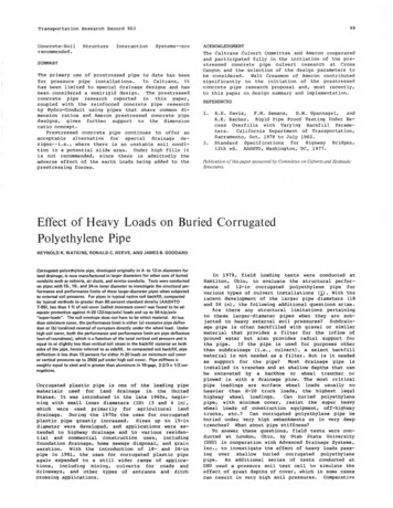
distance from the structure and the geometry of the surrounding area and the structureitself. These forces should then be applied on the structural system at hand in order todesign structural members, sections and connections that will ensure sufficient robustnessof the building to survive the effects of the computed actions.In the current technical guide, an overview of a design procedure for structures under blastloading is provided. The material presented has been collected from various sources andmainly from references [7-9]. The analysis focuses on ways to estimate blast loading onstructures and, to a lesser extent, on their response under such types of actions. Indicativeexamples of structures under explosive loads are also analyzed in order to providedesigners practical guidance on how to deal with similar cases.2.2.1Explosions and blast wavesIdeal blast wave characteristicsAn explosion can be defined as a very fast chemical reaction involving a solid, dust or gas,during which a rapid release of hot gases and energy takes place. The phenomenon lastsonly some milliseconds and it results in the production of very high temperatures andpressures. During detonation the hot gases that are produced expand in order to occupy theavailable space, leading to wave type propagation through space that is transmittedspherically through an unbounded surrounding medium. Along with the produced gases, theair around the blast (for air blasts) also expands and its molecules pile-up, resulting in whatis known as a blast wave and shock front. The blast wave contains a large part of theenergy that was released during detonation and moves faster than the speed of sound.Figure 1 shows the idealised profile of the pressure in relation to time for the case of a freeair blast wave, which reaches a point at a certain distance from the detonation. Thepressure surrounding the element is initially equal to the ambient pressure Po, and itundergoes an instantaneous increase to a peak pressure Pso at the arrival time tA, when theshock front reaches that point. The time needed for the pressure to reach its peak value isvery small and for design purposes it is assumed to be equal to zero. The peak pressure Psois also known as side-on overpressure or peak overpressure. The value of the peakoverpressure as well as the velocity of propagation of the shock wave decrease withincreasing distance from the detonation center. After its peak value, the pressure decreaseswith an exponential rate until it reaches the ambient pressure at tA to, to being called thepositive phase duration. After the positive phase of the pressure-time diagram, the pressurebecomes smaller (referred to as negative) than the ambient value, and finally returns to it.The negative phase is longer than the positive one, its minimum pressure value is denotedas Pso- and its duration as to-. During this phase the structures are subjected to suctionforces, which is the reason why sometimes during blast loading glass fragments fromfailures of facades are found outside a building instead in its interior.2
Figure 1: Ideal blast wave’s pressure time historyThe negative phase of the explosive wave is usually not taken into account for designpurposes as it has been verified that the main structural damage is connected to thepositive phase. Additionally, the pressures that are produced from the negative phase of theblast wave are relatively small compared to those of the positive phase and since these arein the opposite direction, it is usually on the safe side to assume that they do not have a bigimpact on the structural integrity of buildings under blast loads. However, the pressures thatare below the ambient pressure value should be taken into account if the overall structuralperformance of a building during a blast is assessed and not only its structural integrity.As can be seen from Figure 1, the positive incident pressure decreases exponentially. Thefollowing form of Friedlander’s equation has been proposed [2], and is widely used todescribe this rate of decrease in pressure values: tPs (t ) Pso 1 tot b to e (1)where, Pso is the peak overpressure,to is the positive phase duration,b is a decay coefficient of the waveform andt is the time elapsed, measured from the instant of blast arrival.The decay coefficient b can be calculated through a non-linear fitting of an experimentalpressure time curve over its positive phase. Besides the peak pressure, for design purposesan even more important parameter of the blast wave pulse is its impulse because it relatesto the total force (per unit area) that is applied on a structure due to the blast. It is defined asthe shaded area under the overpressure-time curve of Figure 1. The impulse isdistinguished into positive is and negative is , according to the relevant phase of the blastwave time history. Equation (2) gives the expression in the case of the positive impulse,3
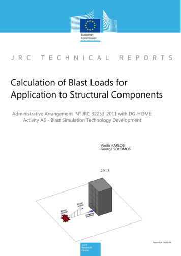
which is more significant than its negative counterpart in terms of building collapseprevention,t A tois P ( t ) dts(2)tAFor the above Friedlander equation (1), the positive impulse can be analytically calculatedasis Pso to b 1 e b ) 2 b(3)This equation constitutes an alternative way for solving iteratively for the decay parameter bwhen the values of the is, Pso and to are known from experimental data.2.2Scaling lawsOne of the most critical parameters for blast loading computations is the distance of thedetonation point from the structure of interest. The peak pressure value and velocity of theblast wave, which were described earlier, decrease rapidly by increasing the distancebetween the blast source and the target surface, as shown in Figure 2. In the figure only thepositive phases of the blast waves are depicted, whose durations are longer whenever thedistance from the detonation point increases.Figure 2: Influence of distance on the blast positive pressure phase.The effect of distance on the blast characteristics can be taken into account by theintroduction of scaling laws. These laws have the ability to scale parameters, which were4
defined through experiments, in order to be used for varying values of distance and
Calculation of Blast Loads for Application to Structural Components Report EUR 26456 EN. European Commission Joint Research Centre Institute for the Protection and Security of the Citizen Contact information George Solomos Address: Joint Research Centre, Via Enrico Fermi 2749, TP 480, 21027 Ispra (VA), Italy E-mail: george.solomos@jrc.ec.europa.eu Tel.: 39 0332 78 9916 Fax: 39 0332 78