Transcription
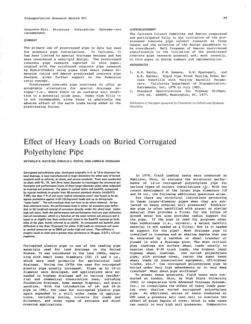
99Transportation Research Record stems--areSUMMARYThe primary use of prestressed pipe to date has beenfor pressure pipe installations.In Caltrans, ithas been limited to special drainage designs and hasbeen considered a semirigid design. The prestressedconcrete pipe research reported in this paper,coupled with the reinforced concrete pipe researchby Hydro-Conduit using pipes that share common dimension ratios and Ameron prestressed concrete pipedesigns, gives further support to the dimensionratio concept.Prestressed concrete pipe continues to offer anacceptable alternative for special drainage des igns--i. e., where there is an unstable soil condition in a potential slide area. Under high fills itis not recommended, since there is admittedly theadverse effect of the earth loads being added to theprestressing forces.ACKNOWLEDGMENTThe Caltrans Culvert Committee and Ameron cooperatedand participated fully in the initiation of the prestressed concrete pipe culvert research at CrossCanyon and the selection of the design parameters tobe considered. Walt Creasmon of Ameron contributedsignificantly to the initiation of the prestressedconcrete pipe research proposal and, most recently,to this paper on design summary and implementation.REFERENCESl .2.R.E. Davis,F.M. Semans,D.W. Spannagel,andA.E. Bacher. Rigid Pipe Proof Testing Under Excess Overfills with Varying Backfill Parameters.California Department of Transportation,Sacramento, Oct. 1978 to July 1982.Standard Specifications forHighway Bridges,12th ed. AASHTO, Washington, DC, 1977.Publication of this paper sponsored by Committee on Culverts and HydraulicStructures.Effect of Heavy Loads on Buried CorrugatedPolyethylene PipeREYNOLD K. WATKINS, RONALD C. REEVE, AND JAMES B. GODDARDCorrugated polyethylene pipe, developed originally in 4- to 12-in diameters forland drainage, is now manufactured in larger diameters for other uses of buriedconduits such as culverts, air ducts, and service conduits. Tests were conductedon pipes with 15-, 18-, and 24-in inner diameter to investigate the structural performance and performance limits of these larger-diameter pipes when subjectedto external soil pressures. For pipes in typical native soil backfill, compactedby typical methods to greater than 80 percent standard density (AASHTOT-99), less than 1 ft of soil cover (called minimum cover) was found to be adequate protection against H-20 (32-kip/axle) loads and up to 54-kip/axle"super-loads". The soil envelope does not have to be select material. At lessthan minimum cover, the performance limit is either (a) excessive pipe deflection or (b) localized reversal of curvature directly under the wheel load. Underhigh soil cover, both the performance and performance limit are pipe deflection(out-of-roundness), which is a function of the total vertical soil pressure and isequal to or slightly less than vertical -soil strain in the backfill material on bothsides of the pipe, herein referred to as sidefill. In compacted soil backfill, pipedeflection is less than 10 percent for either H-20 loads on minimum soil coveror vertical pressures up to 2500 psf under high soil cover. Pipe stiffness isroughly equal to steel and is greater than aluminum in 16-gage, 2-2/3 x 1/2 corrugations.Corrugated plastic pipe is one of the leading pipematerials used for land drainage in the UnitedStates. It was introduced in the late 1960s, beginning with small inner diameters (ID) (3 and 4 in),which were used primarily for agricultural landdrainage. During the 1970s the uses for corrugatedplastic pipe greatly increased.Sizes up to 15-indiameter were developed, and applications were extended to highway drainage and to various residential and commercial construction uses, includingfoundation drainage, home sewage disposal, and grainaeration.With the introduction of 18- and 24-inpipe in 1981, the uses for corrugated plastic pipeagain expanded to a still wider range of applications, including mining, culverts for roads anddriveways, and other types of entrance and ditchcrossing applications.In 1979, field loading tests were conducted atHamilton, Ohio, to evaluate the structural performance of 12-in corrugated polyethylene pipe forvarious types of culvert installations Ill· With therecent development of the larger pipe diameters (18and 24 in), the following additional questions arise.Are there any structural limitations pertainingto these larger-diameter pipes when they are subjected to heavy external soil pressures? Subdrainage pipe is often backfilled with gravel or similarmaterial that provides a filter for the inflow ofground water but also provides radial support forthe pipe.If the pipe is used for purposes otherthan subdrainage (i.e., culvert), a select backfillmaterial is not needed as a filter. But is it neededas support for the pipe?Most drainage pipe isinstalled in trenches and at shallow depths that canbe excavated by a backhoe or wheel trencher orplowed in with a drainage plow. The most criticalpipe loadings are surface wheel loads usually noheavier than H-20 truck loads, the highest legalhighway wheel loadings.Can buried polyethylenepipe, with minimum cover, resist the super heavywheel loads of construction equipment, off-highwaytrucks, etc.? Can corrugated polyethylene pipe beburied under very high embankments or in very deeptrenches? What about pipe stiffness?To answer these questions, field tests were conducted at London, Ohio, by Utah State University(USU) in cooperation with Advanced Drainage Systems,Inc., to investigate the effect of heavy loads passing over shallow buried corrugated polyethylenepipe.An additional series of tests conducted atUSU used a pressure soil test cell to simulate theeffect of great depths of cover, which in some casescan result in very high soil pressures. Comparative
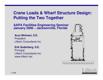
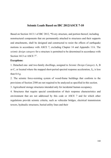
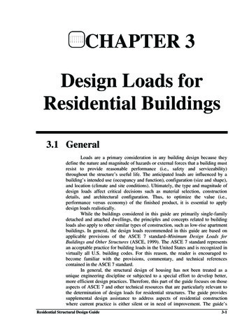
100Transportation Research Record 903NOTATIONbackfilled to the original soil level (as shown inFigure 1) to provide a continuously decreasingheight of cover from one end of each pipe run to theother.The height of cover was determined fromelevations taken along the pipe before and afterbackfilling.The following notation is used in this paper:Materialstests were conducted by the Wadsworth Testing Laboratory of Canton, Ohio, and hy usu on the At i ffnPAAof functionally equivalent corrugated pipes ofsteel, aluminum, and polyethylene.D nominal pipe diameter inside diameter(in) Id depth of corrugation (in),Dm mean diameter of pipe D d (in),B width and height of select soil envelope,usually gravel (in) (in this study, widthand height were equal) ,H height of cover above the top of the pipe(in) IH/D ratio of height of cover to nominal pipediameter (dimensionless) ,6y vertical pipe deflection (in),6y/D a ratio of decrease in vertical diameterto the original circular diameter(dimensionless),y soil density based on AASHTO T99, appliedto native soil in situ, or after compactionof soil backfill (pcf) ,P vertical soil pressure at the top of thepipe (psf) ,c vertical soil strain (in/in), andF/6y pipe stiffness (lb/in of length inof deflection) MINIMUM COVER TESTSProcedureA test course of seven pipe runs was set up at asite near London, Ohio, as shown in Figure 1. Eachpipe run consisted of two 20-ft sections coupledtogether at the midpoint (the midpoint was not ameasurement point).The objective of the testingprogram was to determine, for buried corrugatedpolyethylene pipe, the relation of pipe deflectionto height of soil cover under large wheel loads atvarious backfill densities.A single-axle H-20 load, 16 kips/dual wheel, wasused as the basic load, but "super-loads" up to 27kips/wheel, as might be applied by heavy off-highwayequipment, were also investigated.The standardtruck H-20 rear axle load of 32 kips was simulatedby use of a John Deere model 762 scraper. The frontwheels of the loaded scraper (16 kips each) werecentered directly over the pipe as shown in Figure 2.DeflectionThe pipe deflection under each wheel was measured byusing a spring-loaded, direct-reading deflectometer(see Figure 3).Deflection was measured to thenearest 1/16 in at five loading positions at 3-ftspacings on each side of the midpoint of each 40-ftpipe run, which made a total of 10 measuringpoints/pipe. As the testing proceeded, it becameapparent that deflections were less than 5 percenteven when the height of cover was less than 12 in.To obtain a wider range of deflections, it was decided to remove cover from the shallow end of eachpipe run and to test the pipe with the H-20 load atzero cover.The pipes wereinstalledinslopingtrenchesandThree sizes of corrugated polyethylene pipe weretested:15-, 18-, and 24-in diameters.The recently developed 18- and 24-in-diameter pipes aremanufactured with a slightly angled helical corrugation of approximately 2 . These sizes were comparedwith the annularly corrugated 15-in-diameter pipemanufactured by the continuous extrusion and corrugating process. The pipes used in the tests wererepresentative of standard production material. Thehigh-density polyethylene resins used in the manufacture of the pipes complied with the requirementsof Type III, Class C, category 5 as defined anddescribed in ASTM Dl248. The pipe stiffness valuesrecorded on the test specimens exceeded the proposedminimum pipe stiffness requirements of large-diameter pipe of 40 psi at 5 percent deflection and 30psi at 10 percent deflection.As shown in Figure l, the testing was designedfor three soil densities: 75, 85, and 95 percentAmerican Association of State Highway and Transportation Officials (AASHTO) standard density. Thenative soil at the site was used as backfill on sixof the seven pipe runs. Uncompacted gravel backfill(AASHTO coarse aggregate 57, uncompacted) was usedon run 3. The backfill soil was a mixture of twostrata: a 2. 5-ft stratum ot sandy clay silt (Unified Soil Classification CL) and a sandy silty clayfrom below that depth (CL) The soil backfill around the pipe was compactedby mechanical power tampers as shown in Figure 4.For pipe runs 1, 2, 5, 6, and 7, the soil was compacted in successive lifts of about 6-10 in each,depending on the desired degree of soil density.More lifts and more passes achieved greater density.The soil backfill for pipe run 4 (75 percent specified density) was dumped on and around the pipe witha loader and spread with a dozer blade7 there was nocompaction except the slight compaction due to theD-6 crawler dozer passing over the completed backfill with a track pressure less than or equal to 3psi.A specified density of 75 percent usuallyindicates uncompacted or very lightly compactedsoil. The density of the soil was checked with aTroxler nuclear densitometer at several stationsalong the pipe and at various levels as the backfilling progressed.ResultsThe results of the tests for minimum cover on 24-indiameter pipe subjected to H-20 loads are shown inFigures 5 and 6, where 6y/D is plotted as a function of both height of soil cover in inches and thedimensionless soil cover term H/D. The dashed curvesare power curves of the form (y bxm) that represent the best-fit curves of the data for the 24-inpipe at the three average soil densities of thefield tests--95.8, 91.8, and 75.0 percent. Becausethe soil densities attained on pipes 5 and 7 werenearly equal, the data were combined for analysis.For purposes of design, plots of 95 percent confidence levels were evaluated by using the 24-inpipe data for soil densities of 75, 80, 85, 90, and95 percent standard AASHTO density. These are shownin Figure 6. The 95 percent confidence level plotis that plot below which 95 percent of all test datafall. The test data for pipe 3, uncompacted gravel
Transportation Research Record 903Figure 1. Minimum cover test layout at London, Ohio.101PIPERun0(in .)BackfillNo.DensitySpecifiedAchievedHEIGHT OF COVERH, (in .)DIA. (in.)H 2 (in.)515soil8585.7 2.7218soil8585.2 1 .5324gravel424soil7575 3.5524soil8590.8 1 .3201 .I208II18"248IuncompactedI24"630II24"624Il l24"6624soil9595.8 3.4724soil9592.5 1 .524IIt24"16H-20 LOAD 40I24"I"'40'. ,I(H'H2]\ T!lllllllll!l!lllllllJll''11Ullll!IUllUllI1IIIJ tISLOPING PIPE METHOD OFVARYING HEIGHT OF COVER, H.Figure 2. H-20 standard truck load (32-kip axle load), simulated with JohnDeere scraper, being positioned for deflection measurement.Figure 3. Spring-loaded, direct-reading deflectometer.?I' r I ». ,.,:-·.,ff' ·"' ,, I .,. .,t'.·. -backfill, are also shown in Figure 6.These datafall within the range of cover from 20 to 30 in. Theperformance of the gravel backfill was similar tothat of soil backfill at 95 percent density.For most pipe installations, the maximum allowable ratio of deflection would be set at t.y/D 10percent by the design engineer.This includes asafety factor of 2 based on an assumed performancelimit of 6y/D20 percent.Thus, the safetyfactors inherent in Figure 6 for 24-in pipe aregenerally adequate for design.For comparison of all three diameters, Figure 7shows the 95 percent confidence levels for minimumcover at 85 percent soil den&ity for all three diameters under H-20 loads.The apparent reversal ofpos itions of the 15- and 18-in curves left of H 16in indicates that localized anomalies begin to affect the deflection at very low soil cover.It wasobserved that with less than a foot of soil coverthe deflection is sensitive to tire tread and tirepressure, surface finish (cut by blade after compaction or filled, i.e., backraked by blade), surface
102Transportation Research Record 903soil type, moisture content, etc.This is to beexpected since at very shallow heights of cover liveloads are not uniformly distributed to the underground conduits. It is also noteworthy that to the.right of H 16 in the 24-in-ID plot is lower thanthe other two, which indicates that a 24-in-ID pipeis relativPly deeper in the pressure bulb underH-20 dual wheel than are the smaller pipes. For theH-20 load, separate plots of 6y/D versus H foreach pipe size are proposed as shown in Figure 7.Further details concerning the effects of loads aregiven by Watkins and Reeve ( ).Based on the assumption that the effects of thebackfill density on the 24-in pipe are similar forthe 15- and 18-in sizes, a curve-fitting techniquewas used to interpolate the relation between percentage deflection and height of cover for intermediate soil densities of BO, 85, and 90 percent.These relations for 15-, 18-, and 24-in pipes aregiven in Tables 1-4. The values in Tables 1 and 2are average values from the best-fit curves. Thevalues given in Tables 3 and 4 are at the 95 percentconfidence level.Tables l and 3 give percentagedeflection for various heights of cover, and Tables2 and 4 give height of cover for various percentagedeflections.Tables 3 and 4, at the 95 percentconfidence level, should be used for design. mFigure 4. Compacting backfill with powered tamper.Super-LoadsIn some applications, loads from off-highway-typevehicles, such as large scrapers, m·a y need to betaken into account in the design process. A superload of 54 kips on one axle was achieved by teetering a loaded John Deere model 762 scraper on itsblade. This was done by using the blade as a fulcrum to raise the tractor axle off the ground withthe machine's hydraulic system.The blade bore ontimber blocks cut to simulate single-wheel imprintareao of 12x24 in each. Wh"''"' Lh1 suil cover wasless than 6 in, the 27-kip wheel loads shearedthrough the pipe.For pipe 4 at 75 percent soildensity and soil cover ranging from 20 to 24 in, thepipe deflection ranged from 3 to 7.5 percent. Wherethe cover exceeded about 12 in, the pipe deflectionwas not significantly greater than that for the H-20standard AASHTO truck loading.HIGH SOIL PRESSURE TESTSThe USU soil pressure test cell (see Figures 8 and9) was used to evaluate the structural performanceof 4-ft-long test sections of the 15-, 18-, and24-in-diameter corrugated polyethylene pipe sizesFigure 5. Deflection versus cover height for 24-inpipe under H-20 loading at three average backfilldensities.----Best Fit Power Curvesy bxm0 :: l15z0bmx958'1.24 ,3- .69- 6209111%77 ,6- 1,45- .8775'!1. "33.4- 1.43- 961\ II \ \-\-\',, .\ '\ 0.o;\.O o, 75'Mt9S.5'X )f."-!11.811.- :::.-- -0- - -·- -X.50'Q. O,jllt. .9----- 00o --- o i---.x10- " ----.,. ::j( Q,.-0.15; - 20253035H HEIGHT OF COVER. (INCHES)00.25III0.500.751.001.251.50
103Transportation Research Record 903Figure 6. Deflection versus cover height for 24-inpipe under H-20 loading with 95 percent confi·dance level curves for five backfill densities.--:R. ---- 95% Confidence Curves0)::: lTESTDATASYMBOLS15zAVERAGEBACKFILLDENSITY958% 35H HEIGHT OF COVER . (INCHES)00.250.501.000.751.501.25Figure 7. Plots of 95 percent confidencevalues for deflection versus cover height at 85percent soil density under H-20 loading. 0 15 .DIAMETERz15"\0t3w1024·\\\1-- -1·· ·r- '\J\\"LL","' . .'. ', ."""w018"\550 .'.101520253035H HEIGHT OF COVER. (INCHES)Table 1. Average deflection values by coverheight for 15-, 18·, and 24-in pipe diametersand 80, 85, and 90 percent backfill densities.Avg Deflection(%)CoverHeight15 44443324 in18 0%85 22221I
Transportation Research Record 903104(the usu tests are referred to as high soil pressuretests).In the test cell, performance limits wereidentified and related to corresponding verticalsoil pressures that may be associated with highearth fill in typical cohesionless soils.The objective of this testing was to find the relationbetween deflection and high soil pressures at various soil densities with and without select soil(gravel) envelopes immediately around the pipe.The test schedule was as follows:TestNo.l2Pipe ID!in)2424EnvelopeB (inlNoneNoneProcedureDeflection15 44433333212976554433322222245678910111224in18 ins43332988776JO876554443Deflection le 4. Minimum cover height at 95 percentconfidence level for 15-, 18-, and 24-in pipediameters and 80, 85, and 90 percent backfilldensities.Soil BackfillDensity (!l7575859575EnvelopeB !in)27x2727x2727x2727x27NoneMinimum Height of Cover (in)123Table 3. Pipe deflection at 95 percent confidence level versus cover height for 15-, 18-, and24-in pipe diameters and 80, 85, and 90 percentbackfill densities.Pipe ID!in)1518181815High vertical pressure was applied in the soil cellby hydraulic rams that had sufficient capacity tosimulate depths of soil cover to more than 100 ft.The load was applied in increments, and observationsSoil BackfillDensity (%)8575Table 2. Minimum cover height versus pipedeflection for 15·, 18-, and 24-in pipe diametersand 80, 85, and 90 percent backfill densities.Test 3456718 in15 210876655544444443380%121098766554424 in85%119876655443390%1310876554433332Minimum Cover Height (in)18 in24 inDeflecti 098776241713II98776651713IO8766554315 in17151312IIIO1098
Transportation Research Record 903105Figure 8. USU high vertical soil pressure test cell, showing setup for testingcorrugated plastic pipe.-----?!,.,."',.,."",,"" IIIIII co)I///////Figure 9. USU high vertical soil pressure test cell in operation.No wall buckling, wall crushing, cracking,tJ.y/D.or tearing occurred.At deflections greater thanabout 25-30
concrete pipe research reported in this paper, coupled with the reinforced concrete pipe research by Hydro-Conduit using pipes that share common di mension ratios and Ameron prestressed concrete pipe designs, gives further support to the dimension ratio concept.