Transcription
Designing Your OwnModel RocketThis publication is intended to be used with the Ohio 4-H project 503M Solid-Fuel Rocketry Master,available online at www.ohio4h.org/rocketsaway. To participate, youth should have completed 503Rockets Away! (Solid-Fuel Model Rockets), have rocketry experience comparable to what is required forother advanced-level 4-H projects, and be able to plan and complete the project on their own withminimal supervision or assistance.The project 503M Solid-Fuel Rocketry Master requires a review and acknowledgment of the NAR ModelRocket Safety Code. The code is included in its entirety there and in this publication.
Designing Your Own Model RocketAUTHORD. Mark Ponder, Electrical Controls Designer and Model Rocket Enthusiast (since the 1970s!)REVIEWERSDr. Bob Horton, Extension Specialist, Educational Design and Science Education, 4-H YouthDevelopment, Ohio State University ExtensionSavannah Ponder, M.S., Aeronautical Engineering, and Research Engineer 2013, The Ohio State UniversityOhio State University Extension embraces human diversity and is committed to ensuring that all research and related educational programs areavailable to clientele on a nondiscriminatory basis without regard to age, ancestry, color, disability, gender identity or expression, geneticinformation, HIV/AIDS status, military status, national origin, race, religion, sex, sexual orientation, or veteran status. This statement is inaccordance with United States Civil Rights Laws and the USDA.Keith L. Smith, Associate Vice President for Agricultural Administration; Associate Dean, College of Food, Agricultural, and EnvironmentalSciences; Director, Ohio State University Extension; and Gist Chair in Extension Education and Leadership.For Deaf and Hard of Hearing, please contact Ohio State University Extension using your preferred communication (e-mail, relay services, orvideo relay services). Phone 1-800-750-0750 between 8 a.m. and 5 p.m. EST Monday through Friday. Inform the operator to dial 614-292-6181.
ContentsIntroduction. 2Model Rocket Safety Code . 3Design OptionsClustering . 5Staging. 7Fins .10Nose Cone Options .12Base Options .13Electronics .14Stability .15Center of Gravity .15Center of Pressure (CP) or Point of Pressure .15Swing Test for Stability.17Additional Information for ReviewModel Rocket Motors .18Adhesive Types .18Finishing .20Plagiarism .21Sample Rocket Projects .22Additional Resources .30Designing Your Own Model Rocket1
IntroductionDesigning your own model rocket can be completed in many different ways. This booklet guides youthrough general steps and provides some options to consider as you begin.One of your first decisions is whether you design your own rocket by modifying an existing rocket modelor start from scratch by assembling individual pieces and parts.Modifying an existing rocket model includes changing the manufacturer’s performance specifications orthe rocket’s exterior. Options for modifying a rocket model include increasing engine size, adding stages,or adding engines to create an engine cluster. More information on some of these options is providedwithin this book.“The greater danger for most of usWhen starting from scratch and assembling individual parts,is not that our aim is too high andyou have complete control of what your rocket looks like.we miss it, but that it is too lowThis type of rocket design building is typically done byand we reach it.”purchasing a bulk parts kit package or by “kit bashing.”—MichelangeloDesigner Special packages include a mixture of differentmodel rocketry pieces and are commonly sold at the same stores as manufactured kits. Kit bashingmeans combining two or more manufacturer kits to create a single, custom-designed rocket. The kitscan be identical or different. If you build your rocket from scratch using the kit bashing method, be sureto keep track of which parts came from which kits. In some cases, kit bashing is the most economicalpath to designing your own rocket from scratch.Regardless of the design path you pursue, the recovery system of your rocket is of your choosing—aslong as it works. If your parachute deploys perfectly but your shock cord mount fails, your recoverysystem has failed. If you are in doubt, check your shock cord mount, add an additional layer of glue, andplace another layer of paper over it.Remember, the objective of this project is to show what knowledge you have gained and what you havelearned. “Bigger is not better, but bigger is usually more expensive.” There are reasons for building alarger rocket; however, a kit-bashed rocket with an A-C engine size (18mm) can easily compete with akit-bashed rocket with a D-E engine size (24mm).“Experience is a hard teacher because she gives thetest first, the lesson afterward.”—Vernon LawDesigning Your Own Model Rocket2
Model Rocket Safety CodeRegardless of what your rocket eventually looks like, you must ensure that you follow all aspects of theModel Rocket Safety Code. The safety code has specific guidelines regarding materials, size, andrecovery systems. Pay special attention to them now so that can incorporate them into your design.Effective August 20121. Materials. I will use only lightweight, non-metal parts for the nose, body, and fins of my rocket.2. Motors. I will use only certified, commercially-made model rocket motors, and will not tamperwith these motors or use them for any purposes except those recommended by themanufacturer.3. Ignition System. I will launch my rockets with an electrical launch system and electrical motorigniters. My launch system will have a safety interlock in series with the launch switch, and willuse a launch switch that returns to the "off" position when released.4. Misfires. If my rocket does not launch when I press the button of my electrical launch system, Iwill remove the launcher's safety interlock or disconnect its battery, and will wait 60 secondsafter the last launch attempt before allowing anyone to approach the rocket.5. Launch Safety. I will use a countdown before launch, and will ensure that everyone is payingattention and is a safe distance of at least 15 feet away when I launch rockets with D motors orsmaller, and 30 feet when I launch larger rockets. If I am uncertain about the safety or stabilityof an untested rocket, I will check the stability before flight and will fly it only after warningspectators and clearing them away to a safe distance. When conducting a simultaneous launchof more than ten rockets I will observe a safe distance of 1.5 times the maximum expectedaltitude of any launched rocket.6. Launcher. I will launch my rocket from a launch rod, tower, or rail that is pointed to within 30degrees of the vertical to ensure that the rocket flies nearly straight up, and I will use a blastdeflector to prevent the motor's exhaust from hitting the ground. To prevent accidental eyeinjury, I will place launchers so that the end of the launch rod is above eye level or will cap theend of the rod when it is not in use.7. Size. My model rocket will not weigh more than 1,500 grams (53 ounces) at liftoff and will notcontain more than 125 grams (4.4 ounces) of propellant or 320 N-sec (71.9 pound-seconds) oftotal impulse.8. Flight Safety. I will not launch my rocket at targets, into clouds, or near airplanes, and will notput any flammable or explosive payload in my rocket.9. Launch Site. I will launch my rocket outdoors, in an open area at least as large as shown in theaccompanying table [below], and in safe weather conditions with wind speeds no greater than20 miles per hour. I will ensure that there is no dry grass close to the launch pad, and that thelaunch site does not present risk of grass fires.Designing Your Own Model Rocket3
10. Recovery System. I will use a recovery system such as a streamer or parachute in my rocket sothat it returns safely and undamaged and can be flown again, and I will use only flame-resistantor fireproof recovery system wadding in my rocket.11. Recovery Safety. I will not attempt to recover my rocket from power lines, tall trees, or otherdangerous places.Most of all, be safe and launch for the field size, NOT the rocket size.LAUNCH SITE DIMENSIONSInstalled Total Impulse (N-sec)Equivalent Motor TypeMinimum Site Dimensions (ft.)0.00--1.251/4A, 080.01--160.00160.01--320.00GTwo Gs1,0001,500Designing Your Own Model Rocket4
Design OptionsClusteringClustering, or using two or more rocket motors at once, allows you to lift heavier rockets and payloadsoff of the ground. Clustering black powder motors requires a launch controller that supplies at least 12Volts DC (VDC) to the igniters to ensure all of the motors ignite at the same time. When clustering, keepthe motors as close to the center line of the rocket as you can. If one or more motors fail to light theflight will at least have a lower apogee. Some rockets deploy the recovery system too low or after therocket is on the ground, and others slam into the ground under power. These are some of theunforeseen problems you can encounter when clustering.When clustering motors together with different nozzle diameters, the smaller diameter(s) ignite first,followed by the larger diameter.(Continued on next page.)Designing Your Own Model Rocket5
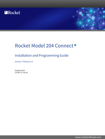
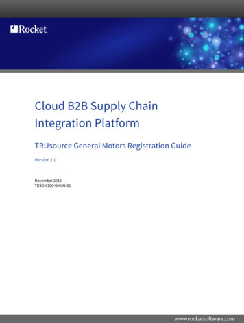
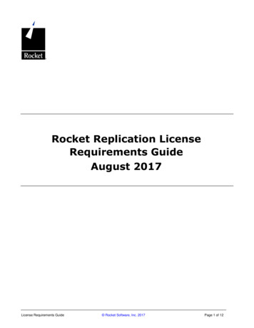
The rocket below clusters two C6-7 and one D12-5 and uses friction motor mounts. The C6-7 engineslight first, followed by the D12-5. The picture on the left shows a successful flight in which all threemotors are inline and lit. The picture on the right shows two of the motors lit in the rocket during anunsuccessful flight. Unfortunately, during this particular launch the owner forgot to friction mount theD12-5 in the center. The C6-7 engines lit first and left the D12-5 behind. You can see the D12-5 engine litin the smoke below the rocket. Just after this picture was taken the rocket was struck by the D12-5,flipped over, and slammed into the ground.Ohio State University ExtensionOhio State University ExtensionOhio State University ExtensionOhio State University ExtensionDesigning Your Own Model Rocket6
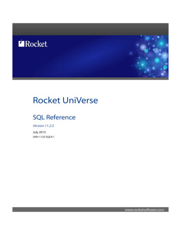
Here are a few typical clustering arrangements. Note that if your fins are located in line with motorsyour rocket will be structurally stronger.Ohio State University ExtensionStagingStaging allows you to increase the performance of the rocket by increasing the rocket’s total impulseand decreasing the rocket’s final weight. A staged rocket has two or more motors that burn one afterthe other while dropping off the used booster(s), where the booster consists of the motor with itsassociated airframe.Different types of solid propellant motors are available and discussed within this book. Black powderrockets are suggested for staging model rockets. Staged rockets with black powder engines can belaunched with standard 6 or 9 VDC launch controllers. Composite motors can be staged; however, thesemotors require electronic timers, altimeters, G-switches, or combinations of these additional pieces ofequipment. Composite motors also require at least a 12 VDC launch controllers. As a result, stagingcomposite motors is not recommended for this project.When staging engines together, an additional degree of risk is introduced to your model rocket duringlaunch. If you have a misfire on a single stage rocket, the rocket will still be on the Launchpad. You canjust replace the igniter and launch with no harm done to the rocket. However, if a two stage rocketmisfires on the second stage, the rocket will fall nose first from 400 to 600 feet without a recoverysystem deployed. The result will be that your rocket will be considerably shorter after the flight. Oncethe rocket leaves the pad you will have no control over it. As a result, be advised that upper stagemisfires can and sometimes will happen when staging rockets.Remember to mark the CG and CP locations for all stages of your rocket. For example, if you have a twostage rocket, it will have two CGs and two CPs marked on the rocket; one for the sustainer section, andone for both stages assembled and ready for launch.Compound StagingCompound staging incorporates both clustering and staging and come with all of the inherent problemsof both.Designing Your Own Model Rocket7
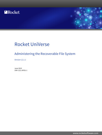
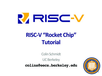
The rocket shown below was built for a rocket challenge by high school students; the challenge was tolaunch two eggs 2,000 feet. It had to carry an altimeter and have at least two stages. The booster carriedtwo D12-3’s and a D12-0 with parachutes, the sustainer carried a E9-5 and a 24” nylon parachute. This iswhere bigger was required to lift the two egg payload.Ohio State University ExtensionDesigning Your Own Model Rocket8
Parallel StagingParallel staging closely resembles clustering but the sustainer has a longer burn time (E9-6) the bustershave more thrust but a shorter burn (D12-3’s). The boosters are ejected after their burn time and in thiscase have their own recovery systems. This is usually controlled by timers or altimeters, but it also canbe done by other means.Ohio State University ExtensionStaged clustersUsing staged clusters involves air-starting the additional motors. Note that on the rocket on the left, thefirst phase has four motors and three in the second. The rocket on the right has three in the first phase,three in the second, and one in the third. The spent motors are still carried by the rocket along with theadditional drag of the larger body tube to house them. This is controlled by using either timers oraltimeters.Ohio State University ExtensionDesigning Your Own Model Rocket9
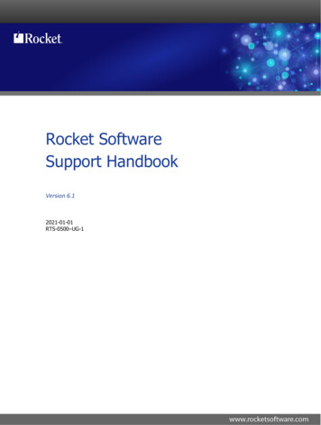
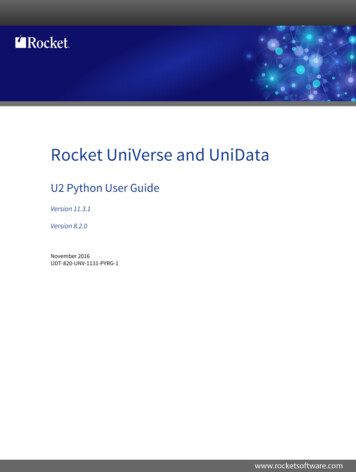
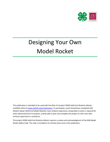
FinsBalsa wood fins are adequate for all forces exerted on a rocket using black powder motors, but only ifthe wood grain is running in the proper direction. When laying out your fins on your material, pay closeattention to the direction of the wood grain. The most efficient way to save material is often incorrect.Fins with the grain running parallel to the body tube break under the stresses of flight. (See drawinglabeled “Incorrect.”) With most fins, the grain running with the leading edge is much stronger. (Seedrawing labeled “Correct.”) Grain direction is important for balsa or basswood fins only; if you are usingplywood fins it is not an issue.Ohio State University ExtensionFor composite motors you must either 1) reinforce the balsa wood by painting the raw wood with CAglue, or 2) change material to basswood or plywood. Reinforced balsa fins are structurally strong but aredifficult to sand to a smooth finish.Designing Your Own Model Rocket10
These images show the best direction of the grain for various fin types.Ohio State University ExtensionDesigning Your Own Model Rocket11
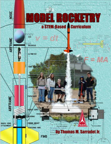
Nose Cone OptionsOptions for nose cones include the ones pictured below and others, all of which create certain amountsof drag. The ones pictured here are arranged in order of increasing drag, with the drag coefficientsappearing below each drawing. As you design your rocket, be aware that there is more to nose coneselection than appearance.Ohio State University ExtensionDesigning Your Own Model Rocket12
Base OptionsLarger diameter rockets have a large amount of base drag inherent the design. Adding a boat tail candecrease the base drag of your rocket. A boat tail is a reducer section in which the smaller diameterfaces the back of the rocket. Be careful if you are adding a boat tail to a short stubby rocket—some ofthese designs rely on base drag as part of their stability.Ohio State University ExtensionDesigning Your Own Model Rocket13
ElectronicsMany electronic devices can be incorporated into a model rocket. Listed below are just a few electronicoptions you can consider.TimersTimers initiate an event such as recovery system deployment staging, air start of additional motors in acluster, or parallel staging. Timers are initiated by an event such as a loss of continuity at launch. Afterthe timer is powered, once the circuit is broken the event happens in however many seconds the timeris set to. Sometimes the motion of carrying a rocket to the launch pad ignites the second stage. For thisreason timers should be powered on and set only on the launch pad.AltimetersAltimeters range from simple devices that tell you the rockets altitude at its apex to more complex unitsthat deploy recovery systems, air start of additional motors in a cluster or parallel staging, staging ofcomposite motors, and data recording of the entire flight downloadable to your computer. Some unitshave G-switches that do not initiate an event until it senses the Gs associated with the rocket’s launch.Altimeters also should be powered only while on the launch pad.CamerasFor many years cameras and video cameras have been incorporated into model rocketry. Now, with theintroduction of digital cameras, light-weight and rugged cameras are available at a reasonable price.LocatorsAfter being armed, a “sonic locators” emits a very loud chirp. Some also include flashing beacons. A“radio locator” allows you to find your rocket using a hand-held receiver. This electronic device makeslocating your rocket easier. However, if you are consistently losing your rockets, make sure your launcharea is at least as big as suggested by the model rocket launch site requirements. You may need to find alarger launch site.LightingWith the addition of LEDs (light emitting diodes) some rockets have been equipped with flashing lights.If you plan to launch a rocket at night, please note that to avoid being in violation of FAA (FederalAviation Administration) regulations, your rocket must weigh less than 16 ounces (1 pound) at liftoff.Designing Your Own Model Rocket14
StabilityStability is one of the most important factors to consider when designing your own rocket. In the Ohio4-H 503 Rockets Away project, when you built from a kit and followed the manufacturer’s instructions,stability was not a concern. Manufactured kits are pre-tested for stability. Since you are not building amanufactured kit for this project, you must show your rocket is stable prior to launch.Never launch a rocket until after its stability has been proven.Proving your rocket is stable involves determining the center of gravity (CG) and center of pressure (CP),also known as the point of pressure. If you have a multistage rocket, you must find all of the CG and CPlocations and show that each stage is stable. Also, don’t forget to test your rocket for stability after youhave painted it and applied any decals. Both can change a rocket’s stability.Center of GravityThe center of gravity is found by finding the balancing point of the prepared rocket. A prepared rocket is“ready launch.” This means your rocket is finished and painted, the recovery system is properlyprepared for flight, and an engine is loaded in your rocket. The engine is not to be armed while findingthe CG location of your rocket. Mark the CG location on your rocket.Ohio State University ExtensionCenter of Pressure (CP) or Point of PressureYou can find the point of pressure using one of these three methods: The Barrowman Method, which is not explained here, involves mathematical calculations. If youchoose to use this method you are expected to show your work.Model rocket software programs, which are not explained here, are readily available. If you usethis method you are expected to show a printout of this information.The cardboard cutout method, described below, works fine for most rockets. This method is thesimplest, but it has its limitations with complex designs relying on base drag or other moreDesigning Your Own Model Rocket15
complex methods to increase stability. (It can show “false” stability issues.) If you use thismethod you are expected to bring your cutout with CP location marked.Cardboard Cutout Method1. Start by drawing your rocket “full size” on a piece of cardboard or foam poster board. Start withthe length and width of the body tube, and then trace the fins and nose cone. Ensure that thecardboard or foam poster is strong enough to keep from bending. For long models, thin woodmay be required.2. Carefully cut out the drawing.3. Find the balancing point of the cutout. This is the CP, or point of pressure.4. Mark the point of pressure on the cutout.5. Measure the point of pressure from the base of the cutout and transfer it to your rocket.Divide the largest diameter of your rocket in half. Compare the half-diameter length to the lengthbetween the CG and CP locations you found on your rocket. If the GG is at least this half-diameter lengthin front of the CP, your rocket is stable.Ohio State University ExtensionDesigning Your Own Model Rocket16
Swing Test for StabilityOne of the best ways to test the stability of a model rocket is with a “swing test.” The steps forconducting a swing test are below, but remember, when you swing the rocket, make sure you are in anopen area away from any people or objects.1. Prepare the rocket by packing the recovery system, including recovery wadding, in your rocket.Then place the heaviest rocket motor that will fit in your rocket. (For example, place a C6-5instead of an A8-3.) No igniter is inserted in the motor for this test.2. Tie a loop in one end of 6-10 feet piece of string. Tie it around the body tube where the rocketbalances horizontally (90 from the string). Place a piece of tape to keep the string from slidingoff the CG.3. Start swinging the rocket overhead with the nose cone facing forward. It may take severalattempts to get the rocket to start this way. If the rocket continues to face forward, continue tostep 4. If the rocket tries to turn around backward, stop the test, and add weight to the nose.This usually can be done by packing some clay into the nose cone. Then repeat steps 1-3.4. Loosen the tape and move the string towards the back of the rocket until the nose points down10 from horizontal then re-tape the string.5. Start swinging the rocket overhead with the nose cone facing forward just like before. If therocket continues to face forward you have a stable rocket. If the rocket tries to turn aroundbackward, stop the test, and add weight to the nose. Then repeat steps 4 and 5.Ohio State University ExtensionDesigning Your Own Model Rocket17
Additional Information for ReviewModel Rocket MotorsBlack Powder MotorsThe most commonly used small model rocket motors are the black powder. These are the "traditional"model rocket motors that have been in production since the 1950s. Black powder model rocket motorsare made of a paper tube with a clay nozzle, a solid pellet of black powder propellant, a smoke/delaycharge, and an ejection charge.Single-Use Composite MotorsSingle-use composite model rocket motors are made from a high temperature plastic and use fuel that isa pellet of a rubber-like material similar to that used in space shuttle booster motors. The fuel in acomposite motor is about three times as powerful as black powder, thus motors of equivalent powercan be made in a smaller physical size. The internal components of a composite motor are much thesame as a black powder motor, except that the nozzle and body of the motor is molded from a hightemperature plastic. The motor body contains the fuel, a smoke/timer charge, and the ejection charge.Reloadable Composite MotorsReloadable composite motors are essentially the same as single-use composite motors. They use thesame fuel, timing charge, and ejection charge. However, reloadable composite motors are assembled ina reusable aluminum case. After the aluminum casing has been cleaned, it can be reassembled with anew nozzle, fuel, delay charge, and ejection charge, and used again. This type of motor should not beused in this project.Hybrid MotorsA hybrid motor works with two different states of matter, one solid and the other either a gas or liquid.The simplest form of a hybrid rocket consists of a pressure tank containing the liquid propellant, thecombustion chamber with the solid propellant, and the valve isolating the two. When thrust is desired,an ignition source is introduced into the combustion chamber and the valve is opened. The liquidpropellant flows into the combustion chamber where it is vaporized and then reacts with the solidpropellant. Rockets using hybrid motors become less stable as the propellant is depleted. This type ofmotor should not be used in this project.Adhesive TypesModel rockets can be assembled using a variety of adhesive types based upon application. The followingexplains a few of the most common adhesives that can be used to assemble your model rocket.Cement for Plastic Models (Model Airplane Glue)Model airplane glue is commonly used to glue nose cone pieces together. This type of glue softens theplastic parts. When the parts are pressed together the plastic flows together and welds. This type of glueDesigning Your Own Model Rocket18
should be used only in well-ventilated areas. There is a non-toxic version of this glue that does notsoften and weld the pieces together. The bond is made by the glue drying and tends to fail due to thestresses placed on the rocket in flight. Non-toxic cement for plastic models should not be used in yourmodel rocket.White GlueWhite glue is exceptionally strong when used on paper products, wood, and other porous materials, butdoes not work on plastic. The long drying time is the biggest complaint for this type of glue. You alsomay have trouble getting some types of paint to adhere to the white glue fillets.Aliphatic Resin GlueAliphatic resin glue looks like a brownish-yellow version of white glue. This glue is very strong, driesfaster than white glue, and most paint adheres to it. Like white glue, aliphatic resin glue works on paperproducts, wood, and other porous materials, but does not work on plastic.Contact CementContact cement is a quick way of bonding two pieces together. To use this type of glue, apply a thin coatto both surfaces, let the pieces set for a few minutes, and then carefully join the two pieces. Thesepieces will be bonded instantly and you will not be able to readjust them. As a result, accuracy isextremely important when using this type of adhesive. Contact cement works on almost any material.EpoxyEpoxy is a strong to exceptionally strong adhesive. This type of adhesive bonds anything except Teflonand some types of PVC (polyvinylchloride). Epoxies have curing times that range from 60 seconds to 24hours. A longer cure time equates to a stronger epoxy. Read the label and know the working time andcure time for the epoxy you are using. Five-minute epoxy sets and cures in 5 minutes; 30 minute epoxyhas a working time of 30 minutes and a cure time of 24 hours. Epoxy can be messy so take appropriatemeasures.CA Glue (Cyanoacrylate)CA glue has almost an instant cure and bonds anything to anything. It is great for quick repairs at thelaunch site. CA glue should only be used in a well-ventilated area as the fumes can be very irritating.Warning: CA glue will bond skin instantly to anything (fingers to fingers, finger to thumb,finger to rocket, finger to glue bottle, etc.). If you are using CA glue, keep a bottle of debonder nearby.“CA Accelerators” speed up the curing of CA glues. These accelerators generate a lot ofheat due to a chemical reaction with the CA glue. When using accelerators you can gluefingers together and burn them! Cotton fibers can react with some CA Glues, so cottonswabs or cotton balls should not be used with CA Glue.Designing Your Own Model Rocket19
FinishingWooden fins should be sealed by using balsa filler coat or sanding sealer. The object is to fill in as muchof the wood grain as possible, allowing for a smooth and professional finish on your rocket. Balsa fillercoat and sanding sealer are applied in the
Designing Your Own Model Rocket 3 Model Rocket Safety Code Regardless of what your rocket eventually looks like, you must ensure that you follow all aspects of the Model Rocket Safety Code. The safety code has specific gu