Transcription
Electrical Engineering Fundamentals:DC Circuit AnalysisCourse No: E07-001Credit: 7 PDHS. Bobby Rauf, P.E., CEM, MBAContinuing Education and Development, Inc.22 Stonewall CourtWoodcliff Lake, NJ 07677P: (877) 322-5800info@cedengineering.com
Electrical Engineering Fundamentalsand Direct Current Electrical Engineering for Non-Electrical EngineersSeries ByS. Bobby Rauf1
PrefaceMany Non-engineering professionals as well as engineers who are notelectrical engineers tend to have a phobia related to electrical engineering.One reason for this apprehensiveness about electrical engineering is due to thefact that electrical engineering is premised concepts, methods andmathematical techniques that are somewhat more abstract than thoseemployed in other disciplines, such as civil, mechanical, environmental andindustrial engineering. Yet, because of the prevalence and ubiquitous nature ofthe electrical equipment, appliances, and the role electricity plays in our dailylives, the non-electrical professionals find themselves interfacing with systemsand dealing with matters that broach into the electrical realm. Therein rests thepurpose and objective of this text.This text is designed to serve as a resource for exploring andunderstanding basic electrical engineering concepts, principles, analyticalstrategies and mathematical strategies.If your objective as a reader is limited to the acquisition of basicknowledge in electrical engineering, then the material in this text shouldsuffice. If, however, the reader wishes to progress their electrical engineeringknowledge to intermediate or advanced level, this text could serve as a usefulplatform.As the adage goes, “a picture is worth a thousand words;” this textmaximizes the utilization of diagram, graphs, pictures and flow charts tofacilitate quick and effective comprehension of the concepts of electricalengineering.In this text, the study of electrical engineering concepts, principles andanalysis techniques is made relatively easy for the reader by inclusion of mostof the reference data, in form of excerpts from different parts of the text,within the discussion of each case study, exercise and self-assessment2
problem solutions. This is in an effort to facilitate quick study andcomprehension of the material without repetitive search for reference data inother parts of the text.Due to the level of explanation and detail included for most electricalengineering concepts, principles, computational techniques and analysesmethods, this text is a tool for those engineers and non-engineers, who are notcurrent on the subject of electrical engineering.The solutions for end of the segment self-assessment problems areexplained in just as much detail as the case studies and sample problem in thepertaining segments. This approach has been adopted so that this text canserve as an electrical engineering skill building resource for engineers of alldisciplines. Since all segments and topics begin with the introduction ofimportant fundamental concepts and principles, this text can serve as a “brushup,” refresher or review tool for even electrical engineers whose current areaof engineering specialty does not afford them the opportunity to keep theirelectrical engineering knowledge current.In an effort to clarify some of the electrical engineering conceptseffectively for energy engineers whose engineering education focus does notinclude electrical engineering, analogies are drawn from non-electricalengineering realms, on certain complex topics, to facilitate comprehension ofthe relatively abstract electrical engineering concepts and principles.Each segment in this text concludes with a list of questions orproblems, for self-assessment, skill building and knowledge affirmationpurposes. The reader is encouraged to attempt these problems and questions.The answers and solutions, for the questions and problems, are included underAppendix A of this text.Most engineers understand the role units play in definition andverification of the engineering concepts, principles, equations, and analyticaltechniques. Therefore, most electrical engineering concepts, principles andcomputational procedures covered in this text are punctuated with properunits. In addition, for the reader’s convenience, units for commonly usedelectrical engineering entities, and some conversion factors are listed underAppendix C.3
Most electrical engineering concepts, principles, tables, graphs, andcomputational procedures covered in this text are premised on SI/MetricUnits. However, US/Imperial Units are utilized where appropriate andconventional. When the problems or numerical analysis are based on only oneof the two unit systems, the given data and the final results can – in most cases- be transformed into the desired unit system through the use of unitconversion factors in Appendix B.Some of the Greek symbols, used in the realm of electricalengineering, are listed in Appendix C, for reference.What readers can gain from this text: Better understanding of some of the electrical engineering terms,concepts, principles, laws, analysis methods, solution strategies andcomputational techniques. Greater confidence in interactions with electrical engineering designengineers, electricians, controls engineers and electrical engineeringexperts. A number of skills necessary for succeeding in electrical engineeringportion of various certification and licensure exams, i.e. CEM,Certified Energy Manager, FE, Fundamentals of Engineering (alsoknown as EIT, or Engineer in Training), PE, Professional Engineeringand many other trade certification tests.An epistemic advice to the reader: if you don’t understand some of theabstract concepts the first time, don’t give up. Read it again! Such is thenature, intrigue and challenge of engineering, physics, science and othersubjects that require thinking, reflection and rumination.4
Table of ContentsSegment 1Electrical Engineering Basics and Direct CurrentFundamental of electrical engineering concepts, terms, principles, laws andequations. Introduction to basic electrical engineering instruments and theiruse.Segment 2Basic DC electrical circuit analysisBasic DC circuit analyses techniques, basic electronic devices and theirapplications. Electronic device recognition and their common functions onprinted circuit boards – a pictorial tour.Appendix ASolutions for self-assessment problemsAppendix BCommon units and unit conversion factorsAppendix CGreek symbols commonly used in electrical engineering5
Segment 1Electrical Engineering BasicsIntroductionIn this first segment of the Electrical Engineering for Non-ElectricalEngineers text, we will explore the basics of electrical engineering termsconcepts, principles, and analytical techniques. Many readers who embark oninvesting time and effort in studying this text are likely to do so for the keypurpose of gaining an introduction into the field of electricity. Many others,on the other hand, might be interested in refurbishing prior knowledge ofelectrical engineering terms, concepts, principles and basic analyticaltechniques. Regardless of whether you belong to one of these two groups – orare simply in pursuit of electrical engineering at the intermediate or associatesdegree level – in this this segment we will lay the foundations in the electricalengineering realm by covering basic electrical engineering terms, conceptsand principles, without the understanding of which, discussion and study ofterms that bear important practical significance, such as power factor, realpower, reactive power, apparent power, load factor, etc. would not be feasible.Most of the material in this segment pertains to DC, or Direct Current,electricity. However, some entities we will discuss in this segment, such as,capacitive reactance, inductive reactance and impedance are fundamentallypremised in the AC, alternating current, realm.Electrical engineering is rooted in the field of physics. Physics, andelectrical engineering, as most other fields in science, depend on empiricalproof of principles and theories. Empirical analysis and verification requiresmeasurement tools or instrumentation. So, after gaining a better understandingof the basic electrical concepts, we will conclude this segment with anintroduction to two of the most common and basic electrical instruments, i.e.multi-meter and clamp-on ammeter.6
VoltageVoltage is defined as an electromotive that moves or pusheselectrically charged particles like electrons, holes, negatively charged ions orpositively charged ions. The term “electromotive” force stems from the earlyrecognition of electricity as something that consisted, strictly, of themovement of “electrons.” Nowadays, however, with the more recentbreakthroughs in the renewable and non-traditional electrical powergenerating methods and systems like microbial fuel cells, and hydrocarbonfuel cells, electrical power is being harnessed, more and more, in form ofcharged particles that may not be electrons.Two, relatively putative, analogies for voltage in the mechanical andcivil engineering disciplines are pressure and elevation. In the mechanicalrealm – or more specifically in the fluid and hydraulic systems – high pressureor pressure differential pushes fluid from one point to another and performsmechanical work. Similarly, voltage – in form of voltage difference betweentwo points, as with the positive and negative terminals of an automobilebattery – moves electrons or charged particles through loads such as motors,coils, resistive elements, lamps, etc. As electrons or charged particles arepushed through loads like motors, coils, resistive elements, light filaments,etc., electrical energy is converted into mechanical energy, heat energy orlight energy. In equipment like rechargeable batteries, during the chargingprocess, applied voltage can push ions from one electrode (or terminal) toanother and thereby “charge” the battery. Charging of a battery, essentially,amounts to the restoration of battery terminals’ or plates’ chemicalcomposition to “full strength.” So, in essence, the charging of a battery couldbe viewed as the “charging” of an electrochemical “engine.” Once charged, achemical or electrochemical engine, when presented with an electrical load,initiates and sustains the flow of electrical current, and performs mechanicalwork through electrical machines.Common symbols for voltage are: E, V, VDC, VAC, VP, VM, VEff,VRMS. Symbols “E” and “V” are synonymous, and both represent voltage. Thesymbol E stands for electromotive force, while V, simply, denotes voltage. Inthe absence of further specification through a subscript, these symbols can besomewhat ambiguous, in that, they could be construed to represent either ACor DC voltage.7
The symbol VAC represents AC voltage. When dealing with ACvoltage, one needs to be specific about whether one is referring to “peak”voltage, VP, or RMS voltage, VRMS. Note that peak voltage, VP, issynonymous with maximum voltage VM. In addition, VEff, the effective (AC)voltage, is the same as, RMS voltage, VRMS. The term RMS stands for RootMean Square Value of AC Voltage. The RMS or effective value of ACvoltage is the work producing portion of the AC voltage. This implies that ACvoltage, current and power, all, have the “work producing” components andthe” non-work producing” components. The work producing components, inessence, transform into - or contribute toward the production of – variousforms of energy, mechanical work and break horsepower – or, to be moreaccurate, break horsepower-hour.Even though detail discussion on the mathematical composition ofRMS voltage is outside the scope of this text, the formula for RMS voltage isas follows:TVRMS VEFF 1V 2 (t). d(t)T0Eq. 1.1AC voltage VRMS, VEff, VP, and VM are inter-related through the followingequations:Vp Vm 2VRMS 2VEFFVRMS Vp2 VmEq. 1.2Eq. 1.32Voltage is measured in volts, or V’s; named after the Italian physicistAlessandro Volta (1745–1827), who invented the first chemical battery.CurrentCurrent consists of movement of electrons, ions, or simply chargedparticles. Movement of electrons can be oscillatory, vibratory or linear. Whenelectrons vibrate or oscillate, the resulting current is AC current. AC current isestablished and sustained by AC voltage. When DC voltage is applied in anelectrical circuit, electrons, ions or charged particles move in one direction.Such linear, unidirectional, movement of charged particles or electrons is DC8
current. DC electrical current is analogous to fluid flow in mechanical orhydraulic systems. Just as pressure, or pressure differential, cause fluid to flowfrom point A to point B, DC voltage drives electrically charged particles tomove from one point to another.Common symbols for current are: I, IDC, IAC, IP, IM, IEff, and IRMS.Similar to the voltage symbols, the symbols of current assume a more specificmeaning through associated subscripts.IAC represents AC current. When dealing with AC current, one needsto be specific about whether one is referring to “peak” current, IP, or RMScurrent, IRMS. Note that peak current, IP, is synonymous with maximumcurrent IM. In addition, IEff, the effective (AC) current, is the same as, RMScurrent, IRMS. The term RMS current stands for Root Mean Square Value ofAC current. The RMS or effective value of AC current is the work producingportion of the AC current. AC current, like AC voltage and AC power, has a“work producing” component and a “non-work producing” component. Thework producing component of AC current contributes toward the productionof mechanical work and break horsepower.The formula for RMS current is as follows:TI RMS I EFF 1 2I (t). d(t)TEq. 1.40AC Current IRMS, IEff, IP, and IM are inter-related through the followingequations:Ip Im 2IRMS 2IEFFI RMS Ip2 ImEq. 1.5Eq. 1.62The unit for current is Ampere named after André-Marie Ampère(1775–1836), a French mathematician and physicist. André-Marie Ampère isrevered as the father of electrodynamics. One amp of current is said to flowwhen electrical charge is flowing at the rate of one Coulomb per second. Thisleads to the following mathematical definition:9
1 Amp of Current 1 - Coulomb of ChargeSecondEq. 1.7This definition of current is analogous to flow rate of fluid quantified in terms of mass flow rate ṁ or volumetric flow rate Q.Example 1.1In an AC system, a voltage source V(t) 156Sin(377t 0 ) volts sets up acurrent of I(t) 15Sin(377t 45 ) amps. The peak voltage and the peakcurrent, in accordance with convention, are 156 V and 15 A, respectively.Calculate the RMS values of voltage and current.Solution:According the Eq. 1.3:VpVRMS VRMS 2Vp 2Vm21562 110 VrmsNote: This is the voltage indicated by a true RMS voltmeter when measuringthe AC voltage at a typical household or workplace wall receptacle. See morediscussion toward the end of this segment.According the Eq. 1.6:I RMS Ip2 IRMS 152Im2 10.6 ARMSNote: This is the current indicated by a true RMS clamp-on ammeter whenmeasuring AC current. See more discussion toward the end of this segment.10
ResistanceProperty of a material that opposes or resists the flow of current isknown as electrical resistance, or simply, resistance. Electrical resistance isanalogous to friction in mechanical systems; for instance, friction between thesurfaces of two objects that slide against each other. In a fluid flow scenario,electrical resistance is analogous to friction between the fluid and the walls ofthe pipe. In electrical systems, resistance in conductors (wires) is anundesirable characteristic and results in wasted heat or heat losses. This is notunlike frictional head losses in fluid systems – frictional head losses governedby Darcy’s equation and Hazen-William’s equations. The symbol forelectrical resistance is “R.” Resistance is measured in ohms, or simply, s.The ohm symbol is often prefixed with letters, such as, k for kilo or M forMega. Where, 1k would represent 1,000 Ohms and 1M would represent1,000,000 ohms.R Vor, V I.RIEq. 1.8An ohm can also be defined on the basis of the Ohm’s Law. TheOhm’s Law and its application in AC and DC systems are discussed in greaterdepth in Segment 2. At this point, upon examination of Ohm’s Law, in formof Eq. 1.8, we can define 1 ohm as the amount of resistance that would permitthe flow of only 1-amp of current when a voltage of 1-volt is applied across aspecific length of that conductor. In other words:1 1-volt1-ampThe Ohm’s Law equation stated above also stipulates that as theincrease in electrical “demand” manifests itself in form of an increase incurrent, I, and as resistance, R, of the conductor increases, the voltage – orvoltage drop – across the conductor increases; resulting in lower voltage at thepoint of delivery of power to the consumers. This is similar to the pressuredrop, or loss, experienced in a long compressed air pipe or header due tofrictional head loss.From physical characteristic and physical composition point of view,we could define resistance as being directly proportional to the length of theconductor and inversely proportional to the area of cross-section of the11
conductor. This proportional relationship can be transformed into amathematical relationship or equation as follows:LAWhere, Resistivity of the Conductor,L Length of the Conductor andA Area of Cross-section of the Conductor. copper 17.2 n m; where, n Nano 10-9 aluminum 28.2 n mR ρ.Eq. 1.9Example 1.2A cubic block of electrically conductive material measures 0.02 on each side.The resistivity of this material is 0.01 Ω m. What is the resistance betweenopposite sides of this block?Solution:R ρL(0.01 Ω-m)(0.02 m) 0.5 ΩA(0.02 m) 2Example 1.3A phase conductor of a power distribution line spans, approximately, 500 ftand has a diameter of 1.5 inch. The conductor is composed of copper.Calculate the electrical resistance of this conductor, per phase.Solution:Solution Strategy: Since the resistivity value of copper, as stated above, is inmetric or SI unit system, the length and diameter specifications stated in thisproblem must be streamlined in metric units before application of Eq. 1.9 fordetermination of resistance in ohms ( s).L 500 ft 152.4 mDiameter 1.5 inch 0.0381m; R Radius D/2 0.019 mA Area of cross-section π.R2 (3.14)( 0.019) 2 0.00113m2 copper 17.2 n m 17.2x10⁻⁹ mR ρ.LA12
R ρ.L 152.4 17.2x10 9 0.00232 A 0.00113 As described earlier, in electrical systems, resistance in conductors(wires) is an undesirable characteristic and results in wasted heat or heatlosses. This energy lost, as heat, as the current flows through a conductor canbe quantified through Eq. 1.10 below.V2Heat Loss P VI I 2 R, in WattsREq. 1.10In an effort to illustrate the substantial impact of resistance on heatlosses and design challenges associated with power transmission, let’scontinue examination of long transmission lines used to transport electricalpower from power generating plants to power consumers. On a hot summerafternoon, those power transmission lines that we notice crisscrossing thecountry side are not only carrying higher currents due to the higher airconditioning loads, but experience an increase in resistance due to increases inresistivity, ρ, of the conductor in accordance with Eq. 1.11. In other words, theresistivity of aluminum, stated above as aluminum 28.2 n m, serves as aconstant only at standard temperature of 20 C or 68 F. 0 1 T T0 0 1 T Eq. 1.11In Eq. 1.11:ρ Resistivity at current temperature “T”ρo Resistivity at standard temperature “To”To Standard temperature in CT Current temperature Cα Thermal coefficient of resistance, in 1/ CIn addition, it’s common knowledge that as temperature rises, mostmetals or conductors expand. So, with exposure to elevated summer seasonsolar radiation, during those hot afternoons, the transmission lines elongate toa certain extent, resulting in higher “L.” As those transmission lines elongate,the diameter of the conductors drops, resulting in lower area of cross-sectionA. So, the perceptible “sag” in the transmission lines during the hot summerafternoons is not simply an optical illusion or a myth.13
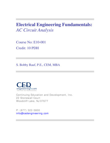
As we account for the increase in L, reduction in A and the rise in ρcollectively, in accordance with Eq. 1.9, we see that all of these factors resultin escalation of resistance. Furthermore, if we consider resistive heat lossequation, Eq. 1.10, the exponential effect of the rise in load current I and theincrease in R precipitate in a “cascading,” unfavorable, physical and electricalimpact on the transmission line conductors.Resistors in seriesWhen electrical circuits, AC or DC, consist of multiple resistors,circuit analyses require simplification of such network of resistors into one,equivalent, resistor or resistance, REQ. Often, this equivalent, resistance isreferred to as a “total” resistance. When “n” number of resistors are connectedin a “daisy chained" or concatenated fashion as shown in Figure 1.1, they aresaid to be connected in series.Figure 1.1: n –Resistors in seriesWhen resistors are connected in series, they can be combined in a“linear addition” format, as stipulated in Eq. 1.12 below, for “n” number ofresistors.REQ RT R1 R2 R3 . RnEq. 1.12When multiple resistors are combined into an equivalent resistor, withresistance value REQ, the simplified version of the original series circuitwould appear as pictured in Figure 1.2.14
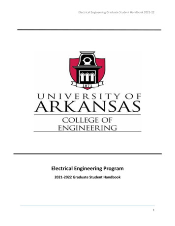
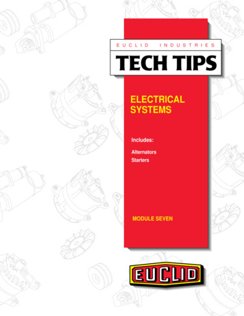
Figure 1.2: Equivalent resistance for n –resistors in seriesResistors in ParallelWhen electrical circuits, AC or DC, consist of multiple resistors,connected in a parallel fashion, as shown in Figure 1.3, circuit analysis wouldrequire simplification of the parallel network of resistors into one, equivalentresistor REQ. Figure 1.3 shows “n” number of resistors connected such thatthe “heads” of all resistors are “bonded” are connected together, with andelectrical connection to the anode (positive terminal) of the DC power supply.In addition, the “tails” of all resistors are connected together and to thecathode of the DC power source.When multiple parallel resistors are combined into an equivalentresistor, with resistance value REQ, the simplified version of the original seriescircuit would appear as pictured in Figure 1.4. In parallel resistor networks,the calculation of REQ involves addition of the inverses of all resistors in theparallel network, and taking the inverse of the sum as stipulated in Eq. 1.13.Figure 1.3: n –Resistors in parallelREQ 11111 . R1 R2 R3RnEq. 1.1315
In case of a simple two parallel resistor circuit, the equivalentresistance REQ could be calculated using the simplified equation, Eq. 1.14.REQ R1 R2R1 R2Eq. 1.14Figure 1.4: Equivalent resistance for n –resistors in parallelAs a special case, assume that the parallel resistor network shown inFigure 1.3 consists of “n” equal parallel resistors. Because, the resistors areassumed to be equal, calculation of REQ, or REQ-n, boils down to Eq. 1.15.R EQ R EQ-n RnEq. 1.15Electrical Short and Open CircuitWhen a conductor, wire or bus-bar, is used to pass current betweentwo or more points in an electrical circuit - with smallest resistance feasible such a connection is referred to as a “short.” A short segment of wire,assembled with an “alligator clip” on each end, is used by electrician andelectrical engineers to establish a temporary short circuit between points in anelectrical circuit. Such a specially fabricated pieces of wire are sometimesreferred to as a “jumper leads,” in electrical jargon.A short circuit between two points implies zero or negligibleresistance. The opposite of an electrical short is an “open circuit.” Examplesof open circuits would be a switch that is open, a breaker that is turned off, orsimply a wire that has been cut or “clipped.” An open circuit between twopoints implies an infinite ( ) resistance. The concepts of open and short16
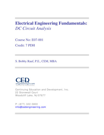
circuits are illustrated in Figure 1.5. Figures 1.5 (a) and (b) represent electricalcircuit segments between points A and B. When the switch between points(1) and (2) is open, as depicted in Figure (a), we have an open circuit, and nocurrent flows between points A and B. However, closure of the same switch,as shown in Figure (b), constitutes a short circuit. The closed switch scenariodepicted in Figure (b) also represents “continuity.” The term “continuity” isused commonly by electrical engineers and electricians during troubleshooting of equipment. When trouble shooting electrical or electronicequipment failures, engineers and technicians often perform continuity testson fuses to determine if they have cleared or opened. The instrument used forperforming continuity checks is a multi-meter. A continuous piece of wire,shown in Figure 1.5 (c), represents continuity between terminals A and B.(a)(b)(c)Figure 1.5: Open and short circuits17
Example 1.4Determine the equivalent resistance for the DC circuit shown below if R1 5 , R2 R3 10 , and R4 R5 20 .Solution:The resistances need to be combined in a multistep process in order todetermine Req for the overall circuit.Combination of R2 and R4 R2,4 R2 R4 10 20 30 Combination of R3 and R5 R3,5 R3 R5 10 20 30 Combination of R2,4 and R3,5:R 2 5 R eq(30 ).(30 )900 15 (30 30 )60 15 5 20 Capacitor and CapacitanceA capacitor is a charge storage device, capable of storing charge in DCand AC applications. A charged capacitor stores electrical charge on twoelectrodes; one of the two electrodes is negative and the other one is positive.The negative electrode is called a cathode and the positive electrode isreferred to as an anode. This separation of charge and the quantity of chargeseparated determine the electrical potential - or voltage - developed across theelectrodes of the capacitor. The electrical potential difference between thecapacitor plates, or electrodes, signifies the storage of electrical energy in thecapacitor. Therefore, as an energy storage device -with a potential difference –capacitors are analogous to air receivers and pneumatic cylinders that store18
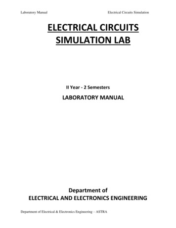
pressure energy - in form of higher pressure relative to the atmosphericpressure – which can be used to perform mechanical work.Construction of a simple capacitor is depicted in Figure 1.6. As shownin Figure 1.6, a simple capacitor can be constructed with two parallel squareplates, of equal size, separated by a dielectric substance like glass, mica, etc.The separation between the two plates (electrodes), “r,” in conjunction withthe area of the plates determines the “capacitance” of the capacitor.Capacitance, “C,” of a capacitor is defined as the charge storage capacity ofthe capacitor.Figure 1.6: A simple parallel plate capacitorCapacitance can be defined, mathematically, through Eq. 1.16, below.C ArEq. 1.16Where,C Capacitance is quantified or specified in farads.A The area of cross-section – or simply area – of the capacitor electrodeplates.Є Permittivity of the dielectric medium between the plates.And, Є Єr . Є0Where, Єr Relative permittivity of a specific dielectric mediumAnd, Є0 permittivity in vacuum or in air 8.854 x 10 12 farads permeter (F·m 1).One farad is rather a large amount of capacitance for most common capacitorapplications. Therefore, many capacitors – especially, at the circuit boardlevel – are specified or labeled in terms of smaller units, such as, mF (milli19
Farad), F (micro-Farad), or nF (nano-Farad). The capacitor shown in Figure1.7 is rated 470 F and designed to operate at a maximum of 35V.Figure 1.7: A cylindrical 470 Micro-Farad CapacitorThe mathematical relationship stated as Eq. 1.16 stipulates thatcapacitance is directly proportional to the area A of the capacitor plates andinversely proportional to the separation r between the plates. In other words, iflarger capacitance or charge storage capacity is desired, one must increase thearea of the plates and/or decrease the separation between the capacitor plates.In addition to serving as a “constant of proportionality” for the equation,permittivity Є injects the property or characteristic of the dielectric mediuminto the computation of capacitance through the dielectric medium’scharacteristic Єr value. Although, for the sake of simplicity, the discussion oncapacitance in this text is limited to flat plate capacitors, many capacitors havecylindrical construction such as the one shown in Figure 1.7.Electrical energy stored in a capacitor can be determined throughapplication of Eq. 1.17Energy (joules) 1CV22Eq. 1.17Charge storage characteristic of the capacitor should not be confusedwith the charge storage and power source function of a battery. One differencebetween capacitors and batteries is that when capacitors are charging ordischarging, charge flows through a “dielectric” medium; while most batteriesconsist of electrolytes (i.e. sulfuric acid) that ionize readily and the ionssustain the flow of current. Capacitors allow the charge to move betweenelectrode plates through a dielectric medium.The dynamics of how a capacitor stores and dissipates charge aresomewhat different between the DC and AC realms. Unlike resistive circuits,current and voltage associated with capacitors vary in a non-linear fashion. Acommon, series, RC circuit is shown in Figure 1.8, consisting of a capacitor,resistor and a switch that can be used to control the charging and discharging20
of the capacitor. The graphs in Figure 1.9 through 1.11 below comparevoltage and current responses in circuits that are purely resistive versus aseries RC circuit, the type illustrated in Figure1.8. This “non-linear” chargingand discharging of capacitors is referred to as transient behavior of RCcircuits.Figure 1.8: A series RC circuitThe straight line graph in Figure 1.9 illustrates and valida
Fundamental of electrical engineering concepts, terms, principles, laws and equations. Introduction to basic electrical engineering instruments and their use. Segment 2 Basic DC electrical circuit analysis Basic DC circui