Transcription
Electrical Engineering Fundamentals:AC Circuit AnalysisCourse No: E10-001Credit: 10 PDHS. Bobby Rauf, P.E., CEM, MBAContinuing Education and Development, Inc.22 Stonewall CourtWoodcliff Lake, NJ 07677P: (877) 322-5800info@cedengineering.com
Electrical Engineering - ACFundamentals and AC Power Topics Electrical Engineering for Non-Electrical EngineersSeries ByS. Bobby Rauf1Electrical Engineering AC Fundamentals and AC Power , Rauf
PrefaceMany Non-engineering professionals as well as engineers who are notelectrical engineers tend to have a phobia related to electrical engineering.One reason for this apprehensiveness about electrical engineering is due to thefact that electrical engineering is premised concepts, methods andmathematical techniques that are somewhat more abstract than thoseemployed in other disciplines, such as civil, mechanical, environmental andindustrial engineering. Yet, because of the prevalence and ubiquitous nature ofthe electrical equipment, appliances, and the role electricity plays in our dailylives, the non-electrical professionals find themselves interfacing with systemsand dealing with matters that broach into the electrical realm. Therein rests thepurpose and objective of this text.This text is designed to serve as a resource for exploring andunderstanding basic electrical engineering concepts, principles, analyticalstrategies and mathematical strategies.If your objective as a reader is limited to the acquisition of basicknowledge in electrical engineering, then the material in this text shouldsuffice. If, however, the reader wishes to progress their electrical engineeringknowledge to intermediate or advanced level, this text could serve as a usefulplatform.As the adage goes, “a picture is worth a thousand words;” this textmaximizes the utilization of diagram, graphs, pictures and flow charts tofacilitate quick and effective comprehension of the concepts of electricalengineering.In this text, the study of electrical engineering concepts, principles andanalysis techniques is made relatively easy for the reader by inclusion of mostof the reference data, in form of excerpts from different parts of the text,within the discussion of each case study, exercise and self-assessmentproblem solutions. This is in an effort to facilitate quick study andcomprehension of the material without repetitive search for reference data inother parts of the text.2Electrical Engineering AC Fundamentals and AC Power , Rauf
Due to the level of explanation and detail included for most electricalengineering concepts, principles, computational techniques and analysesmethods, this text is a tool for those engineers and non-engineers, who are notcurrent on the subject of electrical engineering.The solutions for end of the segment self-assessment problems areexplained in just as much detail as the case studies and sample problem in thepertaining segments. This approach has been adopted so that this text canserve as an electrical engineering skill building resource for engineers of alldisciplines. Since all segments and topics begin with the introduction ofimportant fundamental concepts and principles, this text can serve as a “brushup,” refresher or review tool for even electrical engineers whose current areaof engineering specialty does not afford them the opportunity to keep theirelectrical engineering knowledge current.In an effort to clarify some of the electrical engineering conceptseffectively for energy engineers whose engineering education focus does notinclude electrical engineering, analogies are drawn from non-electricalengineering realms, on certain complex topics, to facilitate comprehension ofthe relatively abstract electrical engineering concepts and principles.Each segment in this text concludes with a list of questions orproblems, for self-assessment, skill building and knowledge affirmationpurposes. The reader is encouraged to attempt these problems and questions.The answers and solutions, for the questions and problems, are included underAppendix A.Most engineers understand the role units play in definition andverification of the engineering concepts, principles, equations, and analyticaltechniques. Therefore, most electrical engineering concepts, principles andcomputational procedures covered in this text are punctuated with properunits. In addition, for the reader’s convenience, units for commonly usedelectrical engineering entities, and some conversion factors are listed underAppendix C.Most electrical engineering concepts, principles, tables, graphs, andcomputational procedures covered in this text are premised on SI/MetricUnits. However, US/Imperial Units are utilized where appropriate andconventional. When the problems or numerical analysis are based on only oneof the two unit systems, the given data and the final results can – in most cases3Electrical Engineering AC Fundamentals and AC Power , Rauf
- be transformed into the desired unit system through the use of unitconversion factors in Appendix B.Some of the Greek symbols, used in the realm of electricalengineering, are listed in Appendix C, for reference.What readers can gain from this text: Better understanding of electrical engineering terms, concepts,principles, laws, analysis methods, solution strategies andcomputational techniques. Greater confidence in interactions with electrical engineering designengineers, electricians, controls engineers and electrical engineeringexperts. A number of skills necessary for succeeding in electrical engineeringportion of various certification and licensure exams, i.e. CEM,Certified Energy Manager, FE, Fundamentals of Engineering (alsoknown as EIT, or Engineer in Training), PE, Professional Engineeringand many other trade certification tests. A better understanding of the many electrical engineering componentsof typical energy projects.An epistemic advice to the reader: if you don’t understand some of theabstract concepts the first time, don’t give up. Read it again! Such is thenature, intrigue and challenge of engineering, physics, science and othersubjects that require thinking, reflection and rumination.4Electrical Engineering AC Fundamentals and AC Power , Rauf
Table of ContentsSegment 1Alternating CurrentIntroduction to single phase AC, differences between AC and DC, ACapplications, complex math based representation of AC circuits and associatedcircuit analysis. Introduction to three phase AC and three phase ACtransformers.Segment 2PowerIntroduction to the concept of power in the DC and AC realms. Comparison ofDC and AC power. Examples of power in practical applications andassociated computations.Segment 3Power FactorExplanation of the concept of power factor on the basis of vectors, voltage andcurrent graphs, power and apparent power. Impact of power factor on overallpower quality, energy productivity, energy cost, mean time between failuresand the kVA demand.Appendix ASolutions for self-assessment problemsAppendix BCommon units and unit conversion factorsAppendix CGreek symbols commonly used in electrical engineering5Electrical Engineering AC Fundamentals and AC Power , Rauf
Segment 1Alternating Current (AC) FundamentalsIntroductionThis segment begins with an introduction to AC, i.e. alternating current,and segues into a comparison between AC and DC. This comparisonaccentuates the complexity of AC as compared with DC due to the use ofcomplex numbers and vectors for complete representation of AC entities andparameters. In this segment, we get an opportunity to appreciate how thecomplexity of AC is amplified by three phase AC consideration in morecommon, industrial and commercial applications. In an effort to allow readersample opportunity to explore and learn basic, single and three phase ACprinciples and mathematical computations, we introduce various single andthree phase AC functions, equations and mathematical techniques; reinforcedby examples and self-assessments problems. The depth to which the readersmay endeavor to explore the topics in this segment depends on their need,appetite and aptitude.Due to the practical applications of the process of electrodeposition, inthe coatings industry - and the innate relationship between electrodepositionand electricity – this process will be defined and illustrated through equationsand practical numerical examples. This segment provides the reader anintroduction to AC electrical transformers of various types; single phase andthree phase. Of course, similar to other topics in this text, the concepts,principles, equations and applications in this segment are illustrated withanalogies, numerical examples and end of the segment problems. All in all,this segment provides an adequate introduction to alternating current andprepares the reader for intermediate level study of AC concepts.Alternating current (AC) versus direct current (DC)The contrast between AC and DC isn’t just rooted in physics but goes asfar back as the 1800’s when, for a period of time, both vied for the residential,commercial and industrial markets. Electricity was first discovered andharnessed, mostly, in the DC, or direct current form. However, due to thephysical constraints associated with transmission, distribution and applicationof DC in industrial, commercial and residential applications, AC vanquishedDC in the power distribution arena. Nevertheless, today DC holds its own in6Electrical Engineering AC Fundamentals and AC Power , Rauf
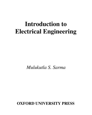
low voltage control and digital logic applications. In fact, albeit rare, DC isbeing reintroduced in the ultra-high voltage realm. The 900,000 Volt DCtransmission line system project, currently underway in India, would serve asa more contemporary testimonial in that regard. This ultra-high DC voltagesystem is expected to redistribute surplus power from India’s hydroelectricrich north east region to the energy starved, high growth, central region.If we could attribute the acceptance of AC for residential, commercialand industrial applications to one pivotal entity, it would be the transformerand concept of voltage transformation. In essence, when DC was firstdistributed and transmitted to end users, it was at a fixed voltage level becauseDC voltage transformation was not feasible. Due to resistance in thetransmission lines - as stipulated by Ohm’s Law: V IR - the DC powergenerators had to be located in the vicinity of the consumers to mitigate theundesirable voltage regulation issues. Longer transmission runs resulted inhigher resistance, or “R,” which, in turn, resulted in larger voltage drop, “V.”In the mechanical fluids realm, this would be analogous to unacceptablepressure drop – due to frictional head losses – if fluid is distributed overextended distances without some sort of booster pumps.Introduction of AC accompanied practical means for “stepping up” and“stepping down” of voltage through the use of transformers. So, AC could begenerated at, for instance, 4,000 volts, stepped up to 100,000 volts – throughthe application of transformers – for transmission purposes, and miles away, itcould be stepped down to usable levels, such as, 480 volt, 240 volts or 120volts. That is, mostly, the way AC is generated, transmitted and distributed toconsumers today.We learnt earlier that movement of electrons, or other charged particles,constitutes electrical current. When the charged particles move in one specificdirection – such that there is a net displacement in their position, or when thecharged particles travel a net distance – direct current, or DC is said to exist.On the other hand, when the electrons or charged particles oscillate or vibrateabout a point – similar to a pendulum - such motion of charged particlesconstitutes alternating current, or AC.If voltage and current were plotted on Cartesian Coordinates, the resultinggraphs would be as depicted in Figures 1.1 and 1.2, respectively. In fact, if AC7Electrical Engineering AC Fundamentals and AC Power , Rauf
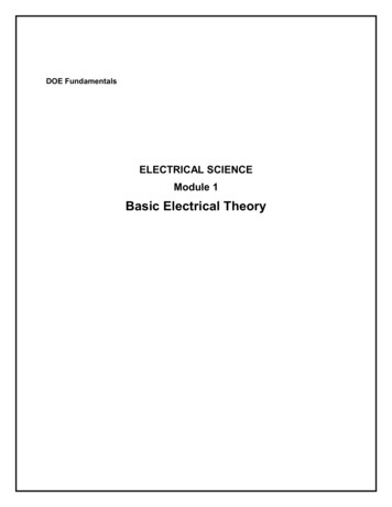
voltage, DC voltage and current were compared using an oscilloscope1, thegraph displayed on the screen would be similar to voltage and current graphsshown in Figures 1.1 and 1.2, respectively.Figure 1.1: Voltage comparison, AC versus DCAs we examine Figure 1.1, we see that the two horizontal flat linesrepresent DC voltage, plotted on two dimensional X-Y coordinates. The lowerflat line represents a typical 12 volt automotive battery. The upper flat line,labeled 100 Volt DC, represents the DC equivalent of 110 VRMS, or 156 Vpeak– i.e. the typical US electrical outlet voltage. The 100 Volt DC equivalent of110 VRMS applies to the DC power derived through full wave rectification ofAC input power. The conversion of AC to DC and associated computationsare illustrated through Example 1.1 and equations introduced in theelectrodeposition section.Further exploration of Figure 1.1 reveals that the x-axis (or abscissa)represents time, t, in seconds. The Y-axis (or ordinate) represents the voltagemagnitude, V, in volts. The sine waveform, oscillating about the time axis,represents the AC voltage, varying as a function of time, t.DC and AC currents can also be contrasted using graphicalrepresentations, in a manner similar to the DC and AC voltage comparisonconducted above.1Oscilloscope is an electrical instrument used to graphically view and analyze voltage,current, frequency or power performance of electrical or electronic systems or circuits.8Electrical Engineering AC Fundamentals and AC Power , Rauf
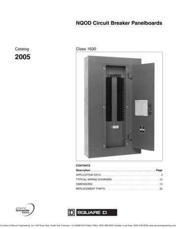
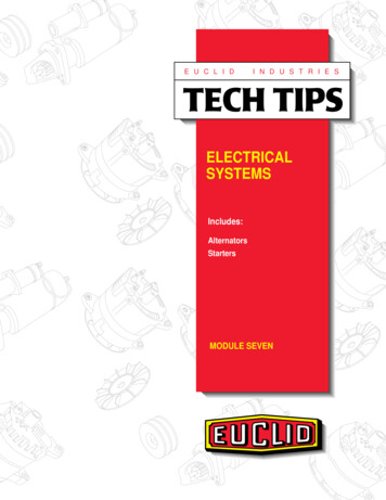
The DC and AC current functions are depicted in Figure 1.2 in a form that issimilar to their voltage counterparts. The horizontal flat line represents the DCcurrent set up by virtue of the DC voltage of the DC power source; which canbe a battery or a DC power supply. The Y-axis of this current vs. time plotrepresents the current magnitude, I, in Amps. The DC current, in this case, isassumed to be a constant 3A.The sine waveform, oscillating about the time axis, represents the AC current,I(t), varying as a function of time, t. The peak or maximum value of the ACcurrent, in this case is assumed to be 10A. Note that in this illustration, the ACcurrent appears to be surfacing into the positive current territory at time t1. Ifone were to assume that this current was produced or driven by the voltagedepicted in Figure 1.1, where the voltage broaches through the x-axis at time t 0, one could say that the current is lagging behind the voltage. As we willexplore later in greater depth, in the power factor section, such a situationwhere current lags behind the voltage is said to cause a lagging power factor.9Electrical Engineering AC Fundamentals and AC Power , Rauf
Figure 1.2: Current comparison, AC versus DCElectrodeposition - DC and the Average Value of ACElectrodeposition, as mentioned earlier, plays an important role in thecoatings operations. Simply put, it involves the use of electrical charge for thedeposition of paint pigments to metallic surfaces. When electrical charge isused to transport paint pigments to a metallic surface, the pigments tend topenetrate and adhere to the metal surface more strongly, uniformly anddurably than if the surface were painted through the traditional spray or brushpainting methods. Since electro deposition process involves net displacementof relocation of the pigments, DC electrical current and voltage have to beemployed. AC voltage, due to the periodic oscillation or reversal of voltage inthe positive and negative realms, would not deliver the net displacement ofthe pigment particles.In electro deposition or electroplating scenarios, often the amount ofelectroplating required is specified in form of the amount of charge that isneeded to be transferred in order to achieve a certain thickness ofelectroplating or electrodeposition. The basic equation that is useful indetermining how long a known amount of DC current must be passed in orderto achieve the required charge transfer is:I DC qq, or, t tI DCEq. 1.1Where, q charge in coulombs of faradays, IDC DC current and t timein seconds. Note that symbols “q” and “Q” may be used interchangeably todenote charge.10Electrical Engineering AC Fundamentals and AC Power , Rauf
Conversion of AC voltage into DC voltage, accomplished through the fullwave rectification, can be quantified using the following equation: V VDC 2. max π Eq. 1.2Where,Vmax 2. VrmsEq. 1.3In order to derive the DC current needed to compute the duration ofelectrodeposition, the effective resistance of the plating tank, with paint – orliquid pigment solution – is needed. This effective resistance can be measured.With the effective resistance known, the DC current can be calculated usingthe Ohm’s law:IDC VDCREq. 1.4A common computation associated with application of AC and DC in theelectrodeposition process is illustrated in Example 1.1.Example 1.1A plating tank with an effective resistance of 150 ohm is connected to theoutput of a full-wave rectifier. The AC supply voltage is 120Vrms. Determinethe amount of time it would take to perform 0.01 faradays worth ofelectroplating?Solution:Background/Theory: The amount of coating or electroplating beingaccomplished in this example is specified in terms of the electrical charge thatmust be moved or transferred; which in this case is specified in Faradays.Faraday is a unit for quantifying electrical charge, similar to Coulomb.1 amp 1 Coulomb/secOr,1(A).(s) 1 CAnd,96,487 Coulomb 1 faraday11Electrical Engineering AC Fundamentals and AC Power , Rauf
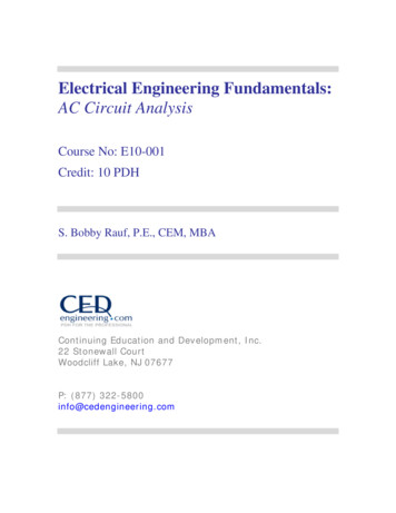
Therefore, the amount of charge transfer in Coulombs, in thiselectrodeposition case, would be: 96,487 Coulombs q . (0.01 Faraday) 964.87 Coulombs1 Faraday Since we are interested in the amount of time it takes to transfer a knownamount of charge, rearrangement of Eq. 1.1 results in:t qIThe next step entails determination of the DC current produced by the fullwave rectification of 120 Vmax AC. The net effect of full wave rectification ofAC into DC is illustrated through the graphs depicted in Figures (a) and (b),below. The graph in Figure (a) shows the AC waveform on the input side of afull wave rectifier.Figure (a)The graph in Figure (b) shows the DC output side of a full wave rectifier;the net effect being the “flipping” or reversing of the negative troughs of theAC waveform such that the resulting output waveform has a definite averagevalue. Note that the average of the sinusoidal AC waveform is zero becausethe AC voltage or current dwells the same amount of time in the positiverealm – or above the x-axis - as it does in the negative realm, or below the x12Electrical Engineering AC Fundamentals and AC Power , Rauf
axis. In other words, on the AC side, since the total positive area portended bythe voltage or current graphs equals the corresponding negative areas on theAC input side of the rectifier, the average value is zero, and the DC content voltage or current - on the AC input side is zero.Figure (b)Based on the data provided, we must first convert the given Vrms voltageinto Vmax using Eq. 1.3, and then compute VDC by applying Eq. 1.2. As shownbelow, these two steps are followed by the application of Ohms Law, in theform of Eq. 1.4, to compute the DC current, IDC.Vmax 2. Vrms (1.414).(120V) 170 V V 170 VDC 2. max 2. 108 V 3.14 π Eq. 1.3Eq. 1.2And,IDC VDCV108 Ave 0.72ARR150Eq. 1.4Then, application of Eq. 1.1 yields:t 964.87 Coulombs 1340 seconds0.72 Coulombs/sec13Electrical Engineering AC Fundamentals and AC Power , Rauf
Alternating Current and ImpedanceImpedance is the current opposing or current impeding characteristic of aload (or conductor) in an AC circuit. As implied in the definition of this term,impedance is an alternating current (AC) entity. While in DC circuits thefactor that opposes the flow of current is resistance, the entity that influencesthe flow of AC current is impedance. Impedance, like AC current, voltage andpower, is a vector entity and, therefore, it can be fully defined by two keycharacteristics, the magnitude and the direction.Mathematical and Geometric Representation of Complex ACEntitiesVector, complex number based entities, such as impedance, AC currentand voltage can be expressed or quantified in the following forms:a)b)c)d)Polar or Phasor formRectangular formSinusoidal formExponential formPolar or Phasor FormThe terms polar and phasor are used synonymously. Phasor or polarrepresentation of AC entities such as impedance, current, voltage and powerrequires definition of the magnitude of the respective entity and the directionin degrees ( ). The polar/phasor representation of AC current would berepresented as follows:I Im θ Eq. 1.5Where, I is the vector or complex value of AC current. The magnitude ofthe overall AC current, unless otherwise specified, is the maximum or peakvalue, and is denoted by Im. In the phasor representation of AC current above,θ is the angle of the AC current.As an example of phasor/polar representation of AC current, consider acurrent I 10 30 A. In this phasor representation of AC current, 10represents the peak or maximum magnitude of AC current in amps, and 30 represents the angle of the current. This is illustrated in Figure 1.3. This14Electrical Engineering AC Fundamentals and AC Power , Rauf
perception or understanding of AC current, as a vector, is analogous to therole of a force vector in mechanical or civil engineering realms; such as, in thestudy of statics, where, the magnitude of a vector entity such as force may bedefined in Newtons (N) or pounds force (lbf) and the direction of the force indegrees.Figure 1.3: Vector representation of phasor value of AC currentNote that in most practical applications and computations, the root meansquare value of current, or Irms, is used instead of the maximum/peakmagnitude of current Imax. For instance, the overcurrent protection devices,i.e., fuses, breakers – and circuit isolation apparatus like the disconnectswitches – to name a few, are specified in rms terms. The same is true for ACvoltages.Rectangular FormRectangular representation of AC entities such as impedance, current,voltage and power entails numerical definition of those entities in form ofhorizontal and vertical, vector, components. An AC current of 10 30 A rms,represented in the polar or phasor form, can be translated to the correspondingrectangular as: 8.66 j5A rms; where the horizontal component of 8.66Arepresents the “real” component of the overall AC current and 5A representsthe “imaginary” or “reactive” component of the overall AC current. Thisconversion of the AC current from its phasor to rectangular form can beaccomplished through a scientific calculator or by performing trigonometric15Electrical Engineering AC Fundamentals and AC Power , Rauf
calculations. The trigonometric approach would involve the computation ofhorizontal and vertical components of the rectangular form, as follows:Ireal 10Cos30 10(0.866) 8.66 AAnd,Ireactive 10Sin30 10(0.5) 5 AIn the mechanical engineering or kinetics realm, the rectangularrepresentation of AC current would be similar to the representation of a10 30 mph velocity vector in the form of its horizontal and verticalcomponents as 8.66 mph and 5 mph, respectively.Sinusoidal or Trigonometric FormThe sinusoidal representation of AC parameters or entities involves theapplication of trigonometry. Sinusoidal representation of an AC entity, such asAC voltage, would be a follows:V V(t) VmSin(ωt θ)Eq. 1.6Where, “V” and V(t) denote sinusoidal AC voltage, Vm is the maximum orpeak voltage, ω represents the angular frequency, in rad/sec, and θ representsthe angle of the AC voltage, in degrees. Figure 1.4, below, depicts this ACvoltage function in the graphical form.Figure 1.4 Graphical representation of sinusoidal voltage16Electrical Engineering AC Fundamentals and AC Power , Rauf
Note that the AC current I, or I(t), would be represented by a graph, verysimilar to the voltage V(t) graph, with the exception of the fact that the I(t)wave form would be shifted to the left or right of the voltage wave form,depending upon whether the reactance of the AC load is predominantlyinductive or capacitive. This is illustrated in Figure 1.5 by a sinusoidal voltageand current graph of a scenario with predominantly inductive load; where, thecurrent is lagging the voltage.Figure 1.5 Graphical contrast between AC voltage and current wave formsContinuing with our example of the 10 30 A rms AC current, we canillustrate its sinusoidal AC form by converting the phasor AC rms currentvalue into its sinusoidal form as:I(t) Irms Sin (ωt θ ) A-rms, in the general form,And,I(t) 10 Sin (377t 30 ) A-rms, in this specific case.Since,Imax 2 .IrmsEq. 1.7 1.41 . 10 14.1AIn peak or maximum value form, the sinusoidal representation would be asfollows:17Electrical Engineering AC Fundamentals and AC Power , Rauf
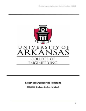
I(t) 14.1 Sin (377t 30 ) AWhere, the coefficient 14.1 represents the maximum value of the current,in amps (A), and 30 represents the angle of the current. The 377 coefficientof time “t” represents, ω, the angular frequency of AC in radians per second.This value of 377 rad/sec is derived from the standard US alternating currentsource frequency of 60 Hz, or 60 cycles/sec. The AC frequency in GreatBritain and some of the former British colonies is 50 Hz. The conversion from60 Hz to 377 rad/sec can be explained mathematically as follows:ω 2.π.f 2.(3.14).(60) 377 rad/secEq. 1.8Exponential FormThe exponential representation of an AC parameter – whether it iscurrent, voltage, impedance or power – is somewhat similar in form to thepolar/phasor form. This is because the exponential form consists of themaximum value and the angle. For instance, the 14.1 30 amp AC currentexample we discussed earlier would be represented in the exponential form asfollows:I Imejθ 14.1ej30 AEq. 1.9Impedance AnalysisIn this section, we will cover mathematical and graphical representationand basic computational methods pertaining to impedance. Becauseimpedance is a vector, it can be drawn or depicted as an arrow whose lengthrepresents the magnitude of the impedance while its orientation, expressed indegrees, represents the angle of the impedance. Since a vector can be analyzedor split into its horizontal and vertical components, impedance “Z” can bedrawn in the vector diagram format as shown in Figure 1.6.18Electrical Engineering AC Fundamentals and AC Power , Rauf
Figure 1.6: Graphical representation of impedance Z in vector formWhen an AC circuit is consists of resistance, capacitance and inductance,impedance Z can be stated mathematically in form of Equations 1.10 and1.11.The unit for impedance is ohm, or ; similar to the unit for resistance, R,capacitive reactance, Xc, and inductive reactance, XL. Consistency of unitsbetween R, XL, XC and Z is a requisite for the following mathematicaldefinitions for Z to hold true:Z R Zl ZcZ R jXl - jXcEq. 1.10Eq. 1.11It’s obvious from examination of the above two equations that:Zl jXlZc -jXcEq. 1.12Eq. 1.13Where, Zl is the impedance contribution by the inductance in the ACcircuit and Zc is the impedance contribution by the capacitance in the ACcircuit. The units for all impedances are ohms, or .Complete comprehension of AC circuit analysis and associatedcomputations requires basic appreciation of how AC circuit components, such19Electrical Engineering AC Fundamentals and AC Power , Rauf
as resistances, capacitances and inductances, are converted into theirrespective impedance contributions before they are consolidated into anoverall equivalent or combined impedance. In most cases, the derivation ofother AC circuit parameters, such as current, voltage and power, is undertakenafter determination of the total or equivalent impedance.Example 1.2Determine the equivalent, or total, impedance ZEq and the source rms current,I, in the AC series circuit below.Solution:According to Eq. 1.10 and Eq. 1.11:Z R Zl ZcOr, Z R jXl - jXcEq. 1.10Eq. 1.111 jω.LjωC1R j(2).(π).(f).(L)j(2).(π).(f).(C)14 j.(2).(3.14).(60).(3 x 10 3 ) 6j(2).(3.14).(60).(700 x 10 )14 j.(1.1304)j(0.2638)4 - j(3.79) j1.1304 4 - j2.66 4.8 -33.63 ZEq R Current “I” calculation:20Electrical Engineering AC Fundamentals and AC Power , Rauf
V(t) Vmax Sin(ωt θ) 156Sin(377t 30 )- Given VP Vmax 156 VAnd, Vrms 156 110 V2 V(t), in rms form, would be Vrms Sin(ωt θ) 110Sin(377t 30 )And, Vrms ,in polar or phasor form would be 110 30 VrmsThen, according to Ohm's Law, I V110 30 ZEq4.8 -33.63Or, I 23 {30 -(-33.63)} The source rms current, I 23 63.63 AExample 1.3Determine the equivalent, or total, impedance ZEq and the rms value of thesource current I in the AC parallel circuit below.Solution:Solution strategy: Convert the given inductance value of L 3 mH into itsequivalent inductive reactance XL, and subsequently into its impedancecontribution ZL. Then, combine the resistance R and ZL values into theequivalent impedance ZEq by applying the formula for combination of parallelcircuit elements.21Electrical Engineering AC Fundamentals and AC Power , Rauf
X L ω.L (377).(3 x 10 3 ) 1.13 ZL j1.13 1.13 90 The parallel combination formula is:111 ZEqRZLOr, ZEq ZEq (R).(ZL )(4).(1.13 90 )(4.52 90 ) R ZL4 j1.134 j1.134.52 90 1.09 74.22 4.16 15.77Current “I” calculation:V(t), in rms form, 110 30 Vrms as determined in the previous example.Then, according to Ohm's Law, I V110 30 ZEq1.09 74.23 The source rms current, I 101 44 ATransformersEarlier in this segment, we introduced the concept of transformers and thehistorically pivotal role transformers played in the predominant acceptance ofAC over DC. In this section, we will explore the technical principles,applications and computations associated with single phase transformers.
understanding basic electrical engineering concepts, principles, analytical strategies and mathematical strategies. If your objective as a reader is limited to the acquisition of basic knowledge in electrical engineering, then the material in this text should suffice. If, however, t