Transcription
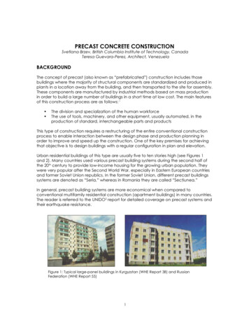
04/11/2015Construction of precast reinforced concrete structuresIstván Vidovszky PhDdefinition2Prefabricated reinforced concrete construction:Construction of RC components of buildings, the majority ofwhich are standardized and produced either at the constructionsite, or (much more often) in plants in a location away from thebuilding, and then transported to the site for assembly.Vidovszky – BUTE/BME-Faculty of Architecture – Department of Construction Technology and Management9/11/20121
04/11/2015general characteristics of precast structures4advantages- economic use of auxiliary materials (formwork, scaffolding) - several repetition(at least 30 identical casts /mould)- reduced construction time - larger quantity of components is possible at thesame time- less skilled labor is requiredlimitations- size of the units- location of window openings has a limited variety- joint details are predefined- site access and storage capacityVidovszky – BUTE/BME-Faculty of Architecture – Department of Construction Technology and Management9/11/2012types3Site-cast (local precast):precast at a plant:-no transportation-the size limitation is depending onthe elevation capacity only- lower quality because directlyaffected by weather- proper, large free space required- transportation and elevationcapacity limits the size- higher, industrialized quality – lessaffected by weather- no space requirement on the site forfabrication- „unlimited” opportunities ofarchitectural appearance- option of standardized components(precast catalogue)Vidovszky – BUTE/BME-Faculty of Architecture – Department of Construction Technology and Management9/11/20122
04/11/2015material5reinforced concreteSCC (self-compacting (consolidating) concrete)– for fair faced concreteCRC (compact reinforced composite)– high strength material for slender structuresGRC (glass-fiber reinforced concrete)Vidovszky – BUTE/BME-Faculty of Architecture – Department of Construction Technology and Managementdisadvantages of precast structures9/11/20126architectural options – surface appearanceplant casting :– allows high quality control– allows greater option of finishes– enable interaction between design phase and production planningVidovszky – BUTE/BME-Faculty of Architecture – Department of Construction Technology and Management9/11/20123
04/11/2015options of surface appearance7surfaces with surface treatment of the materialVidovszky – BUTE/BME-Faculty of Architecture – Department of Construction Technology and Managementoptions of surface appearance9/11/20128classical patterns – with the surface of the form-faceingVidovszky – BUTE/BME-Faculty of Architecture – Department of Construction Technology and Management9/11/20124
04/11/2015options of surface appearance9advanced patterns – with special designed form-facing / CNC-cut patternsVidovszky – BUTE/BME-Faculty of Architecture – Department of Construction Technology and Management9/11/2012options of surface appearance10advanced patterns – with special designed form-facing / CNC-cut patterns1. cutting2. wood/plywood form-facing3. concrete surfaceVidovszky – BUTE/BME-Faculty of Architecture – Department of Construction Technology and Management9/11/20125
04/11/2015building typesOne or two storey hall-like buildings11Multi-storey buildingsVidovszky – BUTE/BME-Faculty of Architecture – Department of Construction Technology and Managementstructure types9/11/201212categories of load-bearing structure- large-panel systems- frame systems- slab-column systems with shear walls- mixed systemsVidovszky – BUTE/BME-Faculty of Architecture – Department of Construction Technology and Management9/11/20126
04/11/2015structure types13large-panel systems- box-like structure,- both vertical and horizontal elements are load-bearing- one-story high wall panels (cross-wall system / longitudinal wall system / twoway system)-one-way or two way slabsVidovszky – BUTE/BME-Faculty of Architecture – Department of Construction Technology and Management9/11/2012structure types14frame systems- components are usually linear elements (beam-pillar frames are rare becausedifficult to handle)- the beams are seated on corbels of the pillars usually with hinged-joints(rigid connection is also an option)- joints are filled with concrete at the siteVidovszky – BUTE/BME-Faculty of Architecture – Department of Construction Technology and Management9/11/20127
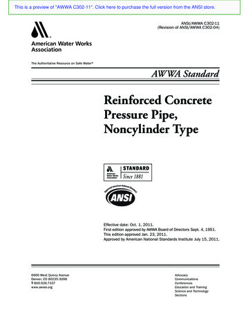
04/11/2015structure types15prestressed slab-column systems- 2-3 storey high pillars- prestressed beams and slab panels (by means of prestressing tendons)- in-situ concreted joints- shear walls (precast or cast-in-place) positioned between the columns atappropriate locations (shear system)Vidovszky – BUTE/BME-Faculty of Architecture – Department of Construction Technology and Managementstructure types9/11/201216prestressed slab-column systems – arrangement of shear wallsgoodunfavourableunfavourableoptimalVidovszky – BUTE/BME-Faculty of Architecture – Department of Construction Technology and Management9/11/20128
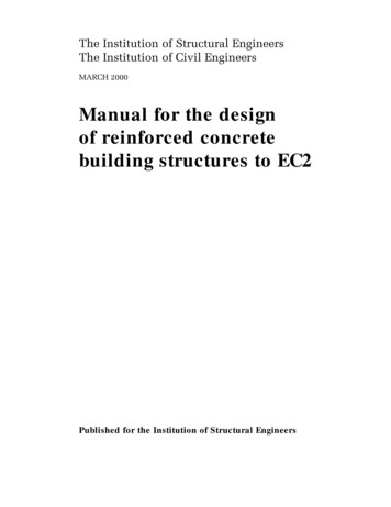
04/11/2015structure types17lift-slab systems- partially precast in plant (pillars) / partially precast on-site (slabs)- one or more storey high pillars (max 5)- up to 30 storey high constructions- special designed joints and temporary joints-slabs are casted on the ground (one on top of the other) – then lifted withcrane or special elevators (two lifting methods: Bulgarian, American)Vidovszky – BUTE/BME-Faculty of Architecture – Department of Construction Technology and Management9/11/2012lift slab procedure181.pillars and the first package (e.g. 5 pieces) of slabs prepared at ground level2. lifting jacks are mounted on the pillars a single slab lifted to the first floor level3-8. boxes are sequentially raised to higher positions to enable the slabs to be lifted to their required finalposition - slabs are held in a relative (temporary) positions by a pinning systemVidovszky – BUTE/BME-Faculty of Architecture – Department of Construction Technology and Management9/11/20129
04/11/2015lift slab procedure9.19extension of pillars10-14.the first package of slabs are lifted further to make space for the next package ofslabs / or new slabs can be fabricated on at a higher level not to disturb the furtherconstruction works at the first levelsAt the end of the lifting process the lifting jacks are removed from the top of the pillarsVidovszky – BUTE/BME-Faculty of Architecture – Department of Construction Technology and Management9/11/2012preparatory work phases201.Design of the building2. Preparation of element consignation3. Planning the transport routes4. Planning the lifting sequence of the elements and the temporary bracingsystem5. Planning the lifting operations – step by step for each elements – Nonisotropic , vulnerable components!!!6. Selection of the temporary structures of the assembly7. Planning the site arrangementVidovszky – BUTE/BME-Faculty of Architecture – Department of Construction Technology and Management9/11/201210
04/11/2015preparatory work phases21Design considerations-final position and loads-transportation requirements – self load and position duringtransportation-storing requirements – self load and position during storing – (avoidor store in the same position as it transported / built in)-lifting loads – distribution of lifting points – optimal way of lifting(selection of lifting and rigging tools)-vulnerable points (e.g. edges) – reduction of risk (e.g. roundededges)Vidovszky – BUTE/BME-Faculty of Architecture – Department of Construction Technology and Managementpreparatory work phases9/11/201222Elements of the structureVidovszky – BUTE/BME-Faculty of Architecture – Department of Construction Technology and Management9/11/201211
04/11/2015preparatory work phases23Element consignationIDFunction1.RcW-012.3.Figure (drawing liftingpoints reinforcement)Geometry (cm) Weight (t)Amountrc wall 01hollowslabpanel400x750x3013,218 Vidovszky – BUTE/BME-Faculty of Architecture – Department of Construction Technology and Managementpreparatory work phases9/11/201224Planning traffic route How long transport-vehicle is required? What is the required load capacity of the transporter vehicle? What is the maximum vertical extension of the shipment? Is route permission required? Routs on the siteVidovszky – BUTE/BME-Faculty of Architecture – Department of Construction Technology and Management9/11/201212
04/11/2015preparatory work phases25Planning traffic routeVidovszky – BUTE/BME-Faculty of Architecture – Department of Construction Technology and Management9/11/2012preparatory work phases26Site arrangement - storing elements on siteOptimal to avoid storing on site!If it is not possible - elements recommended to be storedin similar position to their future built-in position!If it is not possible either - design considerationhave to be made for storing regarding to thereinforcement!Vidovszky – BUTE/BME-Faculty of Architecture – Department of Construction Technology and Management9/11/201213
04/11/2015preparatory work phases27Elevation plan- work sequence- plan of the elevation step by step for each element (pillars, beams,slabs, wall panels)- temporary bracing, supporting system and final shear wallsTemporary structures & site organisation plan!Vidovszky – BUTE/BME-Faculty of Architecture – Department of Construction Technology and Managementpreparatory work phases9/11/201228Elevation plan (example)Vidovszky – BUTE/BME-Faculty of Architecture – Department of Construction Technology and Management9/11/201214
04/11/2015preparatory work phases29Elevation plan (example)Vidovszky – BUTE/BME-Faculty of Architecture – Department of Construction Technology and Managementpreparatory work phases9/11/201230Elevation plan (example)Vidovszky – BUTE/BME-Faculty of Architecture – Department of Construction Technology and Management9/11/201215
04/11/2015equipments31cranes:-moblie crane-tower crane (above 3storeis)lifting tools:-spreader beams-wire rope slingsto eliminateextra loadfrom liftingrigging tools:-eye bolt-shakles-hookson the elements(lifting points)for the craneVidovszky – BUTE/BME-Faculty of Architecture – Department of Construction Technology and Managementselection of mobile crane9/11/201232relevant parameters:1.Lifting heights the level of the final location of the element the height of the highest element the height of the equipment (lifting and rigging tools) 1m2.Lifting weight the weight of the heaviest element to liftVidovszky – BUTE/BME-Faculty of Architecture – Department of Construction Technology and Management9/11/201216
04/11/2015work sequence of the assembly33I. floorvertical load-bearing structure (e.g. pillars or walls)temporary supports (if needed)shear wallshorizontal load-bearing elements (e.g. beams slabs)preparation of the structural jointsNon-load-bearing elements (e.g. non-load-bearing wall panels)II. floor Vidovszky – BUTE/BME-Faculty of Architecture – Department of Construction Technology and Managementassemblyerecting multi-storey pillars9/11/201234lifting wall elementsVidovszky – BUTE/BME-Faculty of Architecture – Department of Construction Technology and Management9/11/201217
04/11/2015assembly35wallpanels with temporary supportslifting slab panelsVidovszky – BUTE/BME-Faculty of Architecture – Department of Construction Technology and Management5. preparing structural joints9/11/201236Foundation types:plain reinforced concreteB.Stepped reinforced concreteC.mass concreteVidovszky – BUTE/BME-Faculty of Architecture – Department of Construction Technology and Management9/11/201218
04/11/2015preparing structural joints37Pillar-beam jointsVidovszky – BUTE/BME-Faculty of Architecture – Department of Construction Technology and Managementpreparing structural jointsSlab-slab joints9/11/201238Beam-slab jointson-site groutedVidovszky – BUTE/BME-Faculty of Architecture – Department of Construction Technology and Management9/11/201219
04/11/2015preparing structural joints39solid wall panelssandwich panel systemWall-jointsVidovszky – BUTE/BME-Faculty of Architecture – Department of Construction Technology and Managementscheduling9/11/201240some aproximate data for installationemplacement of hollow core floor slabs - 300 m2/dayerection of pillars/columns - 8 pieces/dayemplacement of beams - 15 pieces/dayemplacement of double tee slabs - 25 pieces/dayemplacement of walls - 15 pieces/dayconstruction of stair and elevator shafts - 2 floors/dayVidovszky – BUTE/BME-Faculty of Architecture – Department of Construction Technology and Management9/11/201220
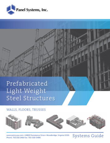
04/11/2015examples41GRC facade wall elements, Office building, 25 – 35 Park Lane, London, United KingdomVidovszky – BUTE/BME-Faculty of Architecture – Department of Construction Technology and Managementexamples9/11/201242SCC construction elements, Office building, 35 Homer Road, Solihull, United KingdomVidovszky – BUTE/BME-Faculty of Architecture – Department of Construction Technology and Management9/11/201221
04/11/2015Thank you for your attention!Vidovszky – BUTE/BME-Faculty of Architecture – Department of Construction Technology and Management9/11/2012ReferencesR[1]Szőnyi L.: Construction of prefabricated reinforced concrete buildings, 2011(Presentation)[2]Benett, D.: Concrete Elegance 2004. Concrete Centre, 2005[3]Precast Concrete Structures. www.paradigm.in 2012.10.10[4]S. Brzev, T. Guevara-Perez: Precast Concrete ST-CONCRETE-CONSTRUCTION-pdfe13174.pdf 2012.10.10[5]Sonjoy Deb: Precast Concrete for Building Building%20Systems.pdf 2012.10.10[6]Lift slab system http://webs.demasiado.com/forjados/patologia/lift lanner.net/steamdrum.html 2012.10.23[8]Vidovszky – BUTE/BME-Faculty of Architecture – Department of
lift slab procedure 1.pillars and the first package (e.g. 5 pieces) of slabs prepared at ground level 2. lifting jacks are mounted on the pillars a single slab lifted to the first floor level 3-8. boxes are sequentially raised to higher positions to enable the slabs to be lifted to their required final