Transcription
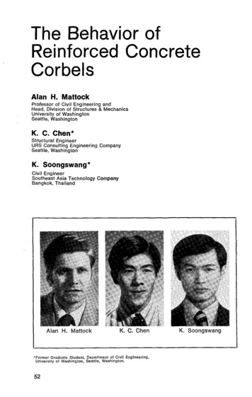
The Behavior ofReinforced ConcreteCorbelsAlan H. MattockProfessor of Civil Engineering andHead, Division of Structures & MechanicsUniversity of WashingtonSeattle, WashingtonK. C. Chen*Structural EngineerURS Consulting Engineering CompanySeattle, WashingtonK. Soongswang*Civil EngineerSoutheast Asia Technology CompanyBangkok, Thailand*Former Graduate Student, Department of Civil Engineering,University of Washington, Seattle, Washington.52
Review of current designprovisions for corbelsCorbels (or brackets) projecting fromthe faces of reinforced concretecolumns are used extensively in precast concrete construction to supportprimary beams and girders.The design of corbels is governed bythe provisions of Section 11.14 of ACI318-71. 1 Under these provisions, corbeldesign may either be based on therather complicated empirical Eqs. (1128) and (11-29), which are valid fora/d 1.0, or if a/d is limited to 0.5,a simpler method of design based onthe shear-friction provisions of Section11.15 may be used.However, when the shear-frictionprovisions are used for corbel design,the limitations on quantity and spacingof reinforcement specified in Section11.14 must still be observed. These limitations derive from the recommendations of Kriz and Raths.2ACI 318-71 requires that unless special measures are taken to avoid horizontal tension forces, all corbels shallbe designed for an appropriate horizontal force N,, in addition to the verticalload V,,, and that Nu/Vu shall not betaken as less than 0.2.In this case the reinforcement ratio pis limited by Section 11.14 tomax. p A / bd 0.13f',/ffthat is:max. pf,, 0.13j'Therefore, using shear-friction:max. v u p0.13 f' 0 o-N.)The normal stress o- is negative fortension. Therefore, when a tension forceN,, acts:N1, /V (O Nx —vn)V.that is:max. V,, /L[0.13f', --. (max. v,,)1Umax.Vuu (V-- j 0.13f'0PC] JOURNAL/March-April 1976SynopsisAn experimental study is reported of the behavior of reinforced concrete corbelssubjected to both verticaland horizontal loads.Twenty-eight corbel specimens were tested, of whichtwenty-six contained hori zontal stirrup reinforcement.The variables included in thestudy were the shear span toeffective depth ratio, the ratio of the vertical load to thehorizontal load, the amountsof main tensile and stirrupreinforcement, and the typeof aggregate.Criteria for the design ofhorizontal stirrup reinforcement are developed.It is shown that, subject toprovision of the recommended amount of stirrup reinforcement, the useful ultimate strength of corbels canbe taken to be the lesser of(a) the shear strength of thecorbel-column interface, calculated using either theshear-friction provisions ofSection 11.15 of ACI 318-71or the modified shear-frictionequation, and;(b) the vertical load corresponding to the developmentof the flexural ultimatestrength of the corbel-column interface.In the next issue a follow-uppaper will propose specificcode provisions for designing corbels together withnumerical examples.53
therefore:max. vu 10.13f,Nuµ V"For corbels monolithic with theirsupporting column, for which µ 1.4,the maximum allowable shear stress dueto the limitation p not greater than0.13f'0 will vary from 0.142f' whenNa/V,, has its minimum value of 0.2,to 0.076f' 0 when NU/VU is equal tounity,* i.e., v y (max.) according to Section 11.14 varies from 71 percent downto 38 percent of the vu (max.) allowedunder the shear-friction provisions ofSection 11.15.The requirement of Section 11.14that horizontal stirrups or ties with anarea A h not less than 0.50A,, be provided, is designed to prevent a prematurediagonal tension or "diagonal splitting"failure of the corbel. This requirementis also based on Kriz and Raths' recommendation.2The provision leads to heavy stirruprequirements when a large N,,, acts withV. However, the data obtained fromtests of corbels with stirrups subject tocombined loading, on which Kriz andRaths based their recommendation, wasrather limited, involving only five specimens with arbitrarily proportioned stirrup reinforcement.In addition to the quantity of stirrupsprovided, the following were also variedin these five specimens—the shear spanto depth ratio, the effective depth, theN„/Va ratio, and the concrete strength.(The reinforcement ratio p A8 /bdwas the same in all the specimens withstirrups.) No upper limit to N,,/V,, is specified in Section 11.14 of ACI 318-71, but Eq. (11-28) inSection 11.14 does not yield sensible results if avalue greater than 1.0 is substituted for N,,/V„in the equation.used in E . (11-28)'The reinforcement ratiois based on the area of the main tension reinforcement only (p A,/bd).p54qThe results obtained in these fivetests were also the basis for a conclusionthat no consistent increase in shear capacity was obtained in a corbel subjectto combined loading, when stirrupswere provided. The requirement in Section 11.14 of ACI 318-71, that the maintension reinforcement only be consideredt when calculating the strength ofa corbel subject to combined loading,stems from this conclusion of Kriz andRaths.Purpose of this studyThe study reported in this paper wasdirected toward the extension of theshear-friction method of corbel designto corbels having shear span to depthratios a/d of up to 1.0, subject to combinations of vertical and horizontalloads such that NU/VU 1.0.It has already been shown 3 that thesimultaneous action of a moment equalto the flexural ultimate strength of acracked section does not reduce theshear which can be transferred acrossthe crack, and that the arbitrary limitation of the use of the shear-friction design method to cases when a/d 0.5is unwarranted.On the basis of the work reportedearlier,3 it was tentatively proposedthat, providing a premature diagonaltension failure of the corbel is prevented by the provision of an appropriateminimum amount of stirrup reinforcement, the ultimate strength of a corbelcan be calculated by taking it to be thelesser of(a) The shear strength of the corbelinterface, calculated using the shearfriction provisions of Section 11.15 ofACI 318-71; and(b) The vertical load correspondingto the development of the flexural ultimate strength of the corbel-column interface, using the provisions of Section10.2 of ACI 318-71.The experimental study reported here
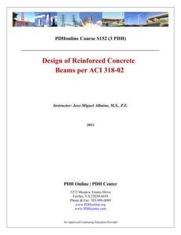
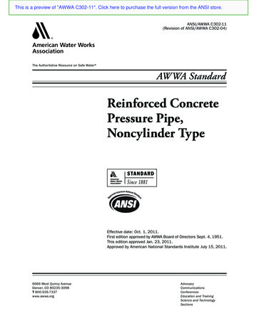
was designed to check the range of applicability of this approach to corbeldesign and to develop rational requirements for stirrups in corbels.A Preliminary considerationsConsider the corbel shown in Fig. la,acted on by a shear V and a horizontalforce N,w. It is assumed that the maintension reinforcement A S and the horizontal stirrups A, 4 can develop their'yield strengths, fv and fvv, respectively.The maximum values of the reactiveforces acting at the interface betweenthe corbel and the column will then beas shown in Fig. 1b, if shear resistancealong the interface is calculated usingthe shear-friction hypothesis.For the corbel to remain in equilibrium the following requirements mustbe satisfied:1. 1F„ 0AhFig. 1a. A typical corbel.We may conservatively neglect thecontribution of the stirrup force OA7, f,,vto the resistance moment and write:V3a N„(h—d id) ,OAj v1d(4)Therefore:i.e., V„ pC(1)2. 1F, 0i.e., N,, A AJ, fA nfvv - C (2)3. 1M 0i.e., V„a N „(h — d id)çt.Ajvjd 4 A ,f„vj1 dAS —4f, d4fv1 dNow jd/j' d is slightly less than 1.0.Therefore, it is conservative to write:A8 . V,,a N,%h — d) NOfv d(3)NowV,,a N1/h — d) N,, jd-f-(5)OfvThat is:idd — Y, ( 4Ajv fA,,f ,p —N,,A,0.85f', b j'd —1/2(6)PAhfa;v(6.85f ,,b )where d would be the internal leverarm if only flexural reinforcement ofstrength (4Aj,, — N„) was acting in thesection, that is:Acv —N, j'd d —(Substituting this value for jd in Eq.(3) and simplifying, we obtain:V„a N„(h—A1 Atd jd) 4A8fvj'd hfvv0.85f c b{j a — 2 ' A f )}PCi JOURNAL/March-April 1976uNuTia InterfaceOAsfy — -jd r04hvy — pd h till,pCFig. 1b. The corbel as a"free body.”55
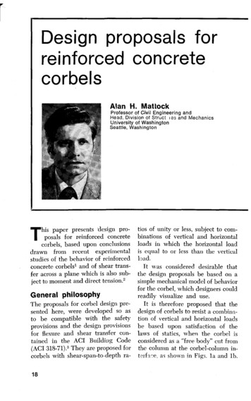
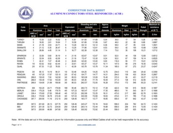
whereAf area of reinforcement necessaryto resist the applied moment[Vua- N,1(h — d)]At area of reinforcement necessaryto resist the horizontal force N,Eliminating C between Eqs. (1) and(2), and simplifying, we obtain:fAh'Iffv Asfr) (7)v ( we may write:oped by Zsutty4 for the shear strengthof directly loaded reinforced concretebeams without stirrups and havingshear span to depth ratios of 2.5 or less:vu2 60v at 60 Mfv A8orAn. Avf At—A8 (8)where A 01 is the area of reinforcementnecessary to carry the shear V,, calculated using the shear-friction Eq. (1130) of ACI 318-71.Substituting for A 8 in Eq. (8) fromEq (6) we have:A 1,, A ,,, —At(9)It is possible that Eq. (9) could yielda very small or zero value for A,,, . However, this would not be admissible, sinceit is presupposed that the amount ofhorizontal stirrups present in the corbelis sufficient to prevent a prematurediagonal tension failure of the corbel. Asuitable minimum amount of stirrupsmust therefore be specified to ensurethis.In this study, it was decided to startwith the hypothesis that the minimumamount of stirrups should be that required to carry the difference in shearbetween the ultimate shear the corbelwas to carry, and the shear at which itwould fail in diagonal tension if no stirrups were provided. It was thereforenecessary to determine a suitable wayof calculating the shear strength of acorbel without stirrups.After reviewing the literature, it wasdecided to examine the applicability tocorbels of the following equation devel56d li3 2.a )( a/d)(10)Eq. (10) was developed from thefollowing equation for the shearstrength of slender beams (a/d 2.5),previously proposed by Zsutty:5V NAf Pf'0pdleada/(11)A study was made of the applicabilityof Eq. (10) to those vertically loadedcorbels tested by Kriz and Raths2 whichwere reported to have failed by "diagonal splitting" (i.e., diagonal tension).The initial calculations showed thatEq. (10) grossly overestimates theshear at diagonal tension failure inmembers with such small values of a/d.A direct comparison was thereforemade of the measured shear stresses at"diagonal splitting" failure, v,,, and the"slender beam" shear strengths, v,,, calculated using Eq. (11).This is shown in Fig. 2. By so doing,it was hoped to determine whetherZsutty's "arching factor," 2.5/(a/d), inEq. (10) could be modified in a simplemanner, or limits be placed on its applicability, so that Eq. (10) could bemade applicable to corbels with smalla/d values.It can be seen that reasonable agreement can be obtained between measured and calculated stresses if an upperlimit of 2.5 is placed upon the factor[2.5/(a/d)].The upper limit controls when a/dis 1.0 or less.It was therefore decided that in thefirst corbel specimens to be tested inthis study, the minimum horizontal webreinforcement would be made equal toPnfvv (min.) Vu — V,,2(12)
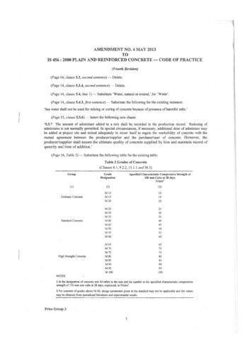
vu 60(ff.p.di)! (2.5)000900Vu800(psi)70000/0 - aid 0.300-,0.30 a/d 0.50/so0 - 0.50 a/d 1.00600500400250200150300Vul 60(fc.p.a '350400(psi)Fig. 2. Comparison of measured and calculated shear stressesat "diagonal splitting" failure in tests of corbels by Krizand Raths. 2 (Corbels subject to vertical load only.)whereExperimental Studypry Ai,/bd design ultimate shear stressd iiav,,0 60 (f op a) K(13)where K 2.5/(a/d)but not greater than 2.5For aid 1.0, Eq. (13) becomes:vuz 150 (fopHence:d its(14)a)d1/3pnfvv (min.) v,, — 150 (ra p a )(15)PCI JOURNAL/March-April 1976A total of 28 corbel specimens weretested, 26 of which contained horizontal stirrup reinforcement. The test program was developed as it progressedand is summarized in Table 1.Series A and B were tested to studyminimum stirrup requirements in corbels designed to carry vertical loadsonly. Series C, D and E were tested tocheck the design method proposedwhen applied to corbels made of sandand gravel concrete, subject to bothvertical and horizontal loads. In SeriesC and E, the design ultimate shear57
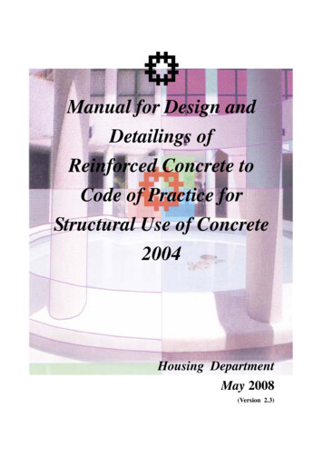
Table 1. Summary of test program.No. ofSpecimensType ofConcreteHorizontalStirrups2Sand &GravelNo08004Sand &GravelYes08004Sand &GravelYes0.75800D3Sand &GravelYes1.0565c4Sand ghtweightYes0H5Sand s was made equal to 0.2f' 800psi the maximum allowable accordingto the shear-friction provisions of Section 11.15 of ACI 318. In Series D andE, the design Nu/V,,, was made equalto the proposed maximum value of 1.0for this method of design. Within eachof these tests series, a/d was varied,having values up to and including 1.0.Series F, G and J were tested tocheck the design method proposedwhen applied to corbels made of alllightweight concrete, subject to bothvertical and horizontal loads. In theseseries also, the limiting values of vu,N u /Vu , and a/d were explored.Series H was tested to examine thepossibility of using the following previously proposed7 equation for theshear transfer strength of sand andgravel concrete, in place of the shearfriction equation when designing -corbels as proposed.(16)v,, 0.8 pfy 400 psibut not greater than 0.3f'c.The specimens were designed for vuequal to the maximum value of 0.3f,simultaneously with N U /V,,, having itsmaximum value of 1.0 and a/d havingvalues up to and including 0.68.Grade 60 reinforcement was used inSeries E through J, to ensure that any58DesignN/VuUDesignvu(psi)8001200560conclusions reached would be valid forcorbels reinforced with this higherstrength steel.Test specimensEach specimen consisted of a 38-in.length of column with two corbels projecting from the column in a symmetrical fashion, as shown in Fig. 3. Themain tension reinforcement consisted ofparallel straight bars, anchored by shortbars of equal diameter welded acrosstheir ends. The closed horizontal stirrups were #2 deformed bars and wereuniformly distributed in the two-thirdsof the effective depth nearest the maintension reinforcement.Steel bearing plates (4 x 1 x 6 in.)were welded to the main tension reinforcement. Series A, B, and G
The corbel as a "free body.” Ah (5) (6) Nu d h PCi JOURNAL/March-April 1976 55. where Af area of reinforcement necessary to resist the applied moment [Vua- N,1(h — d)] At area of reinforcement necessary to resist the horizontal force N, Eliminating C between Eqs. (1) and (2), and simplifying, we obtain: Ah f v ( Asfr) (7) If fv we may write: V N A Mfv A8 or An.Avf At—A8 (8 .File Size: 1MBPage Count: 26