Transcription
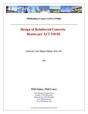
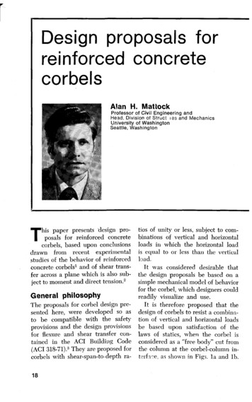
Design proposals forreinforced concretecorbelsAlan H. MattockProfessor of Civil Engineering andHead, Division of Struct 1as and MechanicsUniversity of WashingtonSeattle, WashingtonThis paper presents 'design proposals for reinforced concretecorbels, based upon conclusionsdrawn from recent experimentalstudies of the behavior of reinforcedconcrete corbels' and of shear transfer across a plane which is also subject to moment and direct tension.2General philosophyThe proposals for corbel design presented here, were developed so asto be compatible with the safetyprovisions and the design provisionsfor flexure and shear transfer contained in the ACI Building Code(ACI 318-71).3 They are proposed forcorbels with shear-span-to-depth ra18tios of unity or less, subject to combinations of vertical and horizontalloads in which the horizontal loadis equal to or less than the verticalload.It was considered desirable thatthe design proposals be based on asimple mechanical model of behaviorfor the corbel, which designers couldreadily visualize and use.It is therefore proposed that thedesign of corbels to resist a combination of vertical and horizontal loadsbe based upon satisfaction of thelaws of statics, when the corbel isconsidered as a "free body" cut fromthe column at the corbel-column interfa e, as shown in Figs. la and lb.
Simple design proposals for normal weight andlightweight reinforced concrete corbels arepresented, based on previously reportedexperimental studies.A "Model Code Clause" embodying the designproposals is detailed, together with astep-by-step procedure for practical application.Design examples are included for both normalweight and lightweight concrete corbels usingboth the ACI 318-71 shear-friction provisionsand the modified shear-friction theory.An Appendix section contains charts to facilitateproportioning of the corbel reinforcement.Also included is a programable calculatorprogram for designing reinforced concretecorbels.Use of the design proposals can lead tosavings in reinforcement, particularly if themodified shear-friction theory is used forshear design.Design applied loadReactive forces and momentFig. la. Typical corbel.PCI JOURNAL/May-June 1976Fig. lb. The corbel as a "free body."19
This approach has been demonstrated' to be valid, subject to theprovision of sufficient horizontalstirrups in the corbel, to prevent apremature diagonal tension failureof the corbel.The design of a corbel now reduces to the calculation of the required amounts of reinforcement sothat the interface plane can carrythe reactive forces and moments Vu,N,,, and M,, shown in Fig. 1b, andthe calculation of the necessaryamount of horizontal stirrup reinforcement to prevent a prematurediagonal tension failure of thecorbel.For static equilibrium of the corbel, the reactive forces V. and N,,must be equal to the design verticaland horizontal loads, V,, and N,,, respectively. In addition, the reactivemoment MU must be equal to[V,,a N,,(h-d)] .Conclusions fromprevious investigationThe experimental study alreadyreported1 '2 has demonstrated thefollowing: The provisions of Section 11.15 of ACI318-71 relate to normal weight concrete only. Based on previously reportedstudies,',' it is proposed that for corbelsmade of lightweight concrete, the valuesof given in Section 11.15 be multiplied by 0.75 for all-lightweight concrete weighing at least 92 lb per cu ftand 0.85 for sanded lightweight concrete weighing at least 105 lb per cu ftand in addition that v,, shall not be taken to be greater than(0.2 — 0.07a/d)f,, nor (800 — 780a/d) psifor all-lightweight concrete, and(0.2 — 0.07a/d)f nor (1000 — 350a /d) psifor sanded lightweight concrete.201. The flexural capacity of the interface may be calculated using theprovisions of Section 10.2 of ACI318-71.2. The direct force N. may be resisted by providing additional reinforcement having a yield strengthequal to N,,.3. The shear capacity of the interface may be calculated using theshear-friction provisions of Section11.15 of ACI 318-71, 0 or using the"modified shear-friction" equationspreviously proposed.1'2,44. A premature diagonal tensionfailure of the corbel will not occurif closed stirrups or ties parallel tothe main tension reinforcement areprovided, having a total yieldstrength equal to one-half the yieldstrength of the reinforcement required to resist the moment M,, orone-third the yield strength of thereinforcement required to resist theshear V,,, whichever is the greater.This reinforcement is to be uniformly distributed within the two-thirdsof the effective depth of the interface adjacent to the main reinforcement.If the yield point of the stirrupsis equal to that of the main tension reinforcement, the requiredtotal cross-directional area of thehorizontal stirrups Ah is simply givenbyA, 0.50(A., — At)whereA, total area of main tension reinforcementAt area of reinforcement provided to resist N,,
PROPOSED MODEL CODE CLAUSEBased on the design philosophy discussed above, the following is proposed as a replacement for the existing Section 11.14 of ACI 318-71.Design for shear is based on theexisting shear-friction provisions ofSection 11.15, modified as necessaryfor the case of lightweight concrete.11.14—Special provisions forbrackets and corbels11.14.1—These provisions applyto brackets and corbels having ashear-span-to-depth ratio, a/d ofunity or less, which are subjected toa design horizontal tensile force Nuless than or equal to the design shearforce Vu. The distance d shall bemeasured at a section adjacent tothe face of the support.1.1.14.2—The section adjacent tothe face of the support shall be designed to resist simultaneously, adesign shear V, a design moment[Vz1,a N,, (h-d)] , and a design horizontal tensile force N.u.11.14.2.1—The reinforcementA f required to resist the designshear shall be calculated using thedesign provisions of Section 11.15.'*11.14.2.2—The reinforcement Afrequired to resist the design momentshall be calculated using the designprovisions of Section 10.2.11.14.2.3—The reinforcement Atrequired to resist the design tensileforce Nu shall be taken as N/(bf ).The design tensile force N, shall notbe taken as less than 0.2V,, unlessspecial provisions are made to avoidtension forces due to restrainedshrinkage and creep, so that themember is subject to shear and moment only. The tensile force N,PCI JOURNAL/May-June 1976shall be regarded as a live load evenwhen it results from creep, shrinkage, or temperature change.11.14.2.4—The area of maintension reinforcement A 3 shall bemade equal to (Af At) or (2A,, f/3 At), whichever is the greater.11.14.2.5—The main tension reinforcement shall be anchored asclose to the outer face of the corbelas cover requirements permit, bywelding a bar of equal diameteracross the ends of the main reinforcing bars, or by some other means ofpositive anchorage.11.14.3—Closed stirrups or tiesparallel to the main tension reinforcement, having a total cross-sectional area A h not less than 0.50(A,S— At) shall be uniformly distributedwithin two-thirds of the effectivedepthadjacent to the main tensionreinforcement.11.14.4—The ratio p A8/(bd)shall be not less than 0.04(f'/f ).11.14.5—The depth of the corbelor bracket at the outside edge of thebearing area shall be not less thanone-half the effective depth of thecorbel or bracket at the section adjacent to the face of the support.For corbels made of lightweight concrete, the values of given in Section11.15 shall be multiplied by 0.75 forall-lightweight concrete weighing atleast 92 lb per cu ft and 0.85 for sandedlightweight concrete weighing at least105 lb per cu ft and, in addition, v,,shall not be taken to be greater than(0.2 — 0.07a/d)f,' nor (800 - 780a/d) psifor all-lightweight concrete, and(0.2 — 0.07afd)f,, nor (1000 — 350a/d) psifor sanded lightweight concrete.21
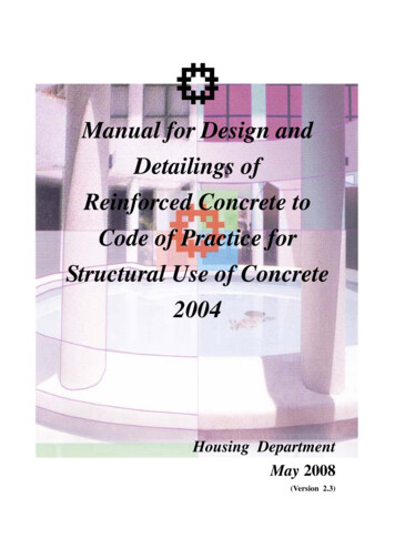
DESIGN PROCEDURE SATISFYING MODEL CODE1. Select tentative proportions forthe corbel, checking that a/d is notmore than 1.0, and that v, is notmore than:(a) 0.2f' nor 800 psi for normal weight concrete;(b) (0.2 — 0.07a/d)f' nor (800— 280a /d) psi for all-lightweight concrete; or(c) (0.2 — 0.07a/d)f' nor (1000— 350 a/d) psi for sandedlightweight concrete.2. Calculate the area of reinforcement A,,f needed across the shearplane to carry shear, using Eq. (1130) of ACI 318-71:tension reinforcement (see Fig. 2),and calculate the design ultimatemoment the corbel-column interfacemust resist:Req. M,, V,,a Nu(h — d) (1)4. Calculate the area of reinforcement Af necessary to provide the resistance moment M, using the provisions of Section 10.2 of ACI 318-71and a capacity reduction factor 0 of0.9.*5. Calculate the area of reinforcement A t necessary to resist the horizontal force N5 , using:V.Avf 4) f µwhere 0 0.85.For corbels cast monolithicallywith the column:µ 1.40 for normal weightconcrete 1.4(0.85) 1.19for sanded lightweightconcrete (unit weight notless than 105 lb per cu ft)1.4(0.75) 1.05for all-lightweight concrete (unit weight notless than 92 lb per cu ft)3. Estimate the distance (h — d)from the top face of the corbel bearing plate to the centroid of the mainAt 4)fv(2)where 4) is 0.85.6. Check whether Af is greaterthan 2A f/3. If A is greater than2A„f/3, calculate the total area ofmain tension reinforcement, using:A, A f A t(3)If Af is less than 2A f/3, calculatethe total area of main tension reinforcement, using:A, 2A,,f/3 At(4)7. Check that p Ag /(bd) is notless than 0.04(f 5' /f5).8. Calculate the total cross-sectional area of horizontal stirrup reinforcement A TE, making A,, equal to0.50 (A, — A t). Distribute this reinforcement in the two-thirds of theeffective depth adjacent to the maintension reinforcement.9. Recheck the dimensions of thecorbel and in particular compute thedepth of the outer face of the corbelin accordance with Section 11.14.5of Model Code Clause.It can be shown that A f /bd is less than0.75pb for the worst case of v„ 0.210',aid 1.0, and N.N. 1.0, if (h-d)/dis assumed equal to 1/8, fa 6000 psi,and fv C 60 ksi. (The reinforcement ratiop actually equals 0.70Pb for this limitingcase.)
reinforcement )diameter as stirrupsFig. 2. Typical corbel reinforcement.ALTERNATE DESIGN METHOD FOR SHEARThe design of the interface for shearv,' - 0.8pvf, 250 psi ( 7 )0,' -may alternatively be based on the&bdfoliowing "modified shear-friction"but not more than (0.2 - O.O7a/d)fdequations previously p r o p o s e d . l , nor (1000 - 350a/d) s i,. .1. For normal weight concrete: , , / ( b dn,ust)be not ,,,,v,v, -- 0.8p,.f, 400 psi( 5) bdbut not more than 0.3fd.2. For all-lightmweight c o n c r e t ehaving a unit weight of not less than92 lb per cu ft:vu-hrd0I t r - -- 0.8p,,f, 200 psi(6 )but not more than (0.2 - 0.07a/d)f,'nor (800 - 280a/d) psi.3. For sanded-lightweight c o n crete having a unit weight of notless than 105 1b per cu ft:,Aless than 200/f, in all cases.For design purposes Eqs. (5), (6),and (7) may be transposed as follows, where V,, is in lb and f , is inpsi,1. For normal weight concrete:A,,, (V,'/ - 400bd)/(O.Bf,) (5A)2. For all-lightweight concrete:AOf (V,,/ - 200bd)/(0.8f,) (6A)3. For sanded l i g h t w e i g h t concrete:Avr (V?i/ - 250hd)/(0.8fv) (7A)In all cases, Art must be not less
than 200bd/ f,,, and the upper limitsto the value of vu must also be observed.If V,ti is given in kips and f , inksi, these equations may be restatedas follows:Avf { Vu/(0.84) — Kbd] /f, (8)but not less than 0.2bd/f,whereK 0.50 for normal weightconcreteorK 0.25 for all-lightweightconcreteorK 0.31 for sanded lightweightconcreteNote: When this method of designfor shear is used and the design(ultimate) shear stress exceeds 1000psi, then if a/d exceeds 0.6, a checkmust be made that Af/(bd) is lessthan 0.75pb.Advantages of ProposedDesign MethodAn important advantage of the design method proposed is its simplicity of concept and the avoidanceof complicated empirical equations.This enables the engineer to developa feel for the way the corbel resistsforces and hence for the reasonableness of his designs.Use of the design proposals canlead to savings in reinforcement,particularly if the modified shearfriction theory is used for shear design.Also, higher design shear stressescan be used than currently allowedby ACI 318-71, if the modifiedshear-friction theory is used for sheardesign. Although not always desirable, this can be convenient incertain circumstances.DESIGN EXAMPLESIn this section two fully-worked design examples are presented applying the preceding design proposals:(1) using a normal weight concretecorbel and (2) a lightweight concrete corbel.The problem in Example 1 is approached employing two methods.In the first method the corbel isassumed to be moderately reinforced and in the second the corbelis designed to have a specified overall depth.In both Examples 1 and 2 theproblem is solved using the ACI318-71 shear-friction provisions andthe proposed modified shear-friction24theory and in each case the reinforcing steel requirements compared.Finally, the last part in this section contains some practical comments on the reinforcing steel details.EXAMPLE 1(Normal weight concrete)Design a corbel (see Fig. 3) which is toproject from the face of a 14 x 14-in.column and carry the following loads:(a) Vertical dead load of 32 kips.(b) Vertical live load of 30 kips.(c) Horizontal force of 24 kips dueto restraint of beam creep andshrinkage deformations.
Assume normal weight concrete withf,.' 5000 psi and let the yield strengthof the reinforcing steel be f, 60 ksi.Design loads (ultimate)V,, 1.4V„-I-1.7VL 1.4(32) 1.7(30) 95.8 kipsN,, 1.7N 1.7(24) 40.8 kipsUsing a 14 x 4 x 1-in, bearing plate,check the bearing stress:1. Moderately reinforced corbelFor a moderately reinforced corbel inwhich the reinforcement should be reasonably easy to place, assume that thenominal shear stress, v 1,, is about 600psi. The depth of the corbel can thenbe found from:V.vu — Abd95,80
considered as a "free body" cut from the column at the corbel-column in-terfa e, as shown in Figs. la and lb. 18. Design applied load Reactive forces and moment Simple design proposals for normal weight and lightweight reinforced concrete corbels are presented, based on previously reported experimental studies. A "Model Code Clause" embodying the design proposals is detailed, together with a .File Size: 1MBPage Count: 25