Transcription
Welcome to430431 Reinforced Concrete DesignLecture 1 - IntroductionInstructor: Mongkol JIRAVACHARADETSchool of Civil EngineeringSuranaree University of Technology ก ก ก ก ก, 4 (2550) , ! " ก ก #ก" , 2 (2540), ก % & ' ( ) ! " ก ก # & * , 5 (2539), ก % & ' ( )
TEXTBOOKSReinforced Concrete: Mechanics and Design, 5th EditionJames G. MacGregor, James K. Wight, Prentice Hall, 2009.Design of Concrete Structures, 13th EditionArthur H. Nilson, David Darwin, Charles W. Dolan,McGraw-Hill, 2003.Reinforced Concrete: A Fundamental Approach, 6th EditionEdward G. Nawy, Prentice Hall, 2009.Building Code Requirements for Structural Concrete,ACI318-08,American Concrete Institute, 2005.TA444 N38 2009TA683.2 W53 2009
TA683.2 N55 2004TA683.2 M39 2009TA683.2 H365 2005TA683.2 R48 2008
Course Objectives ก ก ก ก ก ก ! " ก # ก ก ก ! % & !' & ( ก ก ก ก ก กMore than just trial and error, design is based on built up experienceas well as a solid background in analysis and an understanding of theparameters affecting a good design solution.Conduct of CourseDesign Projects20 %Midterm Exam40 %Final Exam40 %
Grading PolicyFinal ScoreGrade100 - 90A89 - 85B 84 - 80B79 - 75C 74 - 70C69 - 65D 64 - 6059 - 0DF* ', ก-. & ( " /0 ' ' ) ( WARNINGS !!!1) Participation expected, check 80%2) Study in groups but submit work on your own3) No Copying of Project4) Submit Project at the right place and time5) Late Project with penalty 30%6) No make up quizzes or exams
Reinforced Concrete Design (RC Design)Content: Specifications, Loads, and Design Methods Strength of Rectangular Section in Bending Shear and Diagonal Tension Design of Stairs, Double RC Beam, and T-Beam Analysis and Design for Torsion Design of Slabs: One-way, and Two-way Bond and Achorage Design of Column, and Footing ServiceabilityReinforced Concrete DesignLecture 1 : IntroductionTopics Covered Structural Design Concept Mechanical Properties of Concrete Steel Reinforcement Reinforced Concrete Structures
Structural Design ConceptStructural Engineering 1 ( '(* ก " ) & 2 * & 3 - * ', 3' ) & % ( ) & & " 1 ) & % ( ) & %3ก * ก % 1 * * )') & * 2 ก " 2 4 4 )' (2 1 )
Structural Design Concept Stability Economy Safety Environment ServiceabilityLIFE-CYCLE OF STRUCTURENew DesignTraditionalactivitiesConstructionMaintenance / Repairs /RenovationRemoval / FailureLesscompetitors
/& / 20 . . 2553
Concrete & Steel PropertiesWhat is Concrete?Concrete is a mix of :Water Cement Ratio (W/C) :Low W/C0.30.7High StrengthLow WorkabilityHigh W/CLow StrengthHigh WorkabilityOptimal ratios obtainedby trial and experience
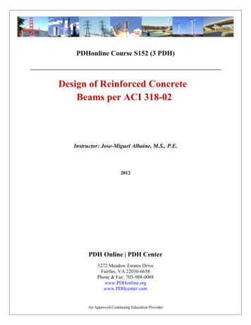
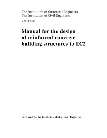
Compressive Strength of Concretef c′ compression test of standard cylinder at 28 days 15 cm30 cm15 cmASTM15 cm BS15 cm( fc′) ASTM 0.85 ( f c′) BSNormal used: 210, 240, 280, 320 kg/cm2High strength: 350 - 700 kg/cm2 . . . . . 2522 : 150 kg/cm2Compressive strength, kgf/cm2Effect of water-cement ratio on 28 days compressive strength500For type Iportland cement450Non400Ai350300r-en tr-air -ainened250t rainecondc reconcretete2000.40.50.60.7Water-cement ratio, by weight
Tensile Strength of Concrete- Greatly affects cracking in structures.- Tensile strength is about 10-15% of compressive strength.Splitting Tensile Test (ASTM C496):Pf ct D2Pπ LDPLf ct 1.59 1.86f c′ kgf/cm 2 for normal-weight concretef ct 1.33 1.59f c′ kgf/cm 2 for light-weight concrete ก ) 3 แรงกด ก 0 ) แรงดึง
Tensile Strength in FlexureStandard Beam Test (ASTM C78):Pfr Mc Modulus of ruptureIPractical choice for design purposesf r 7.5 f c′ psi 2.0 f c′ kscStress-Strain Relationship of ConcreteσInitial modulusf c′0.5 f c′Secant modulusat 0.5 f c′ Ec 0.003Ultimate strainεcuεASTM
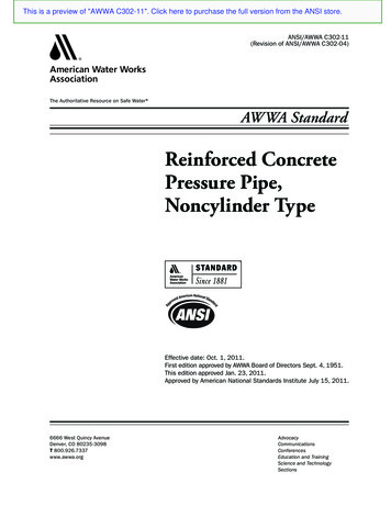
Concrete & Steel Strength-DeformationsσSteelCompression LREINF.RODfsfyCONCRETEfyfyεc L/L εsConcretefc1 fc2ε1 ε2εyf’c0.85f’cStrainε3 εcuεcmFailureStrainTensionModulus of elasticityConcrete:Ec 33 w1.5cf c′ psilb/ft3 psiEc 4, 270 wc1.5t/m3Ec 15,100Steel:LEs 2.04 106 kscf c′ ksckscf c′ ksc for wc 2.32 t/m3
Concrete WeightPlain concrete 2.323 t/m3Steel 7.850 t/m3Reinforced concrete 2.400 t/m3Lightweight concrete 1.6 - 2.0 t/m3Steel ReinforcmentRound Bar ( กก )SR24: Fy 2,400 ksc, Fu 3,900 kscDeformed Bar ( ก %&&%& )SD30: Fy 3,000 ksc, Fu 4,900 kscSD40: Fy 4,000 ksc, Fu 5,700 kscSD50: Fy 5,000 ksc, Fu 6,300 ksc
Stardard Reinforcing Bar Dimension and WeightBAR 46.315.977.868.8010.06Reinforced Concrete
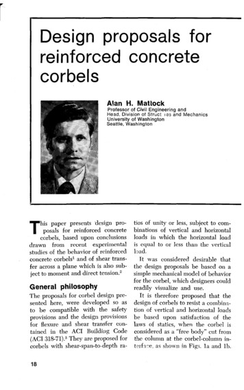
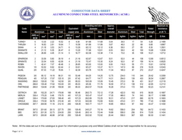
Reinforced Concrete (RC) StructuresPANeutral axiscompression zonetension zoneAConcreteSteel barsSteel barsSection A-AConcrete:high compressive strengthbut low tensile strengthSteel bars: embedded in concrete (reinforcing)provide tensile strengthSteel and Concrete in Combination(1) Bond between steel and concrete prevents slipof the steel bars.(2) Concrete covering prevent water intrusionand bar corrosion.(3) Similar rate of thermal expansion,Concrete:0.000010 - 0.000013Steel:0.000012
WHY Reinforced Concrete? Concrete is cheaper than steel Good combination of Concrete & Steel Durability from concrete covering Continuity from monolithic jointDisadvantages of RC Construction time Concrete Quality Control Cracking of Concrete
Typical StructureSpandrelbeamColumn2nd FloorJoistBeam1st FloorSpread footingWall footingTypical StructureColumnFloor slabMain beam(Girder)SpandrelbeamPierFoundation(Footing)
คานรอยแตกร �รอยแตกร าวเนือ่ �ดแรงดึงรอยแตกร ��แรงดึงสูงสุด
�ึง ตามการแอ /6 Wขนาดแรงดึง kPa2/6 W3/6 W4/6 W5/6 �ของแรงดึง ณ จุดต างๆแรงดึงต่ํา
��กรีตระนาบของรอยร าวที่เป นไปได ซึ่งต �� �ตัวของคานเหล็กเส นรับแรงดึง
รอยแตกร าวเนือ่ �ปลอกที่ใช �หลังคานรอยแตกใต ท องคาน
�ากทรุดรอยแตกใต ท องคานการแตกร าวที่ผนัง เป �ัวโครงสร าง
Reinforced Concrete DesignLecture 2 -Specification, Loads andDesign Methods Structural Design Process Building Codes Working Stress Design Strength Design Method Dead Load & Live Load Load Transfer in StructureMongkol JIRAVACHARADETSURANAREEINSTITUTE OF ENGINEERINGUNIVERSITY OF TECHNOLOGYSCHOOL OF CIVIL ENGINEERINGDesign ProcessArchitecturalFunctional PlansFinal Design& DetailingSelect StructuralSystemOKTrial Sections,Assume SelfweightAnalysis for internalforces in memberRedesignAcceptable?NGDesign LoopMember Design
SpecificationsDeveloped by organizations such as AISC, ACIASCE, and EITRecommendations of good practice based onthe accepted body of knowledgeNOT legally enforceableOrganizationsEIT Engineering Institute of ThailandASCE American Society of Civil EngineersAASHTO American Association of State Highwayand Transportation OfficialsUBC Uniform Building CodeBOCA Building Officials & Code AdministratorsACI American Concrete Institute
Building Codes ก ก Minimum requirements to protect the public- . . . 2522- "" #ก - % "" #Design LoadsDead Loads - stationary loads of constantmagnitudeLive Loads - moving loads or loads that varyin magnitude
& ก ก (Dead Load)Caused by the weight of structureInclude both the load bearing and non-loadbearing elements in a structureGenerally can be estimated with reasonablecertainty & ก / ก0 / 12 ก ก ก ก ก !"ก # % & ' ก ( , * ก ก!""# "% ก!""# ( )" 60100-200
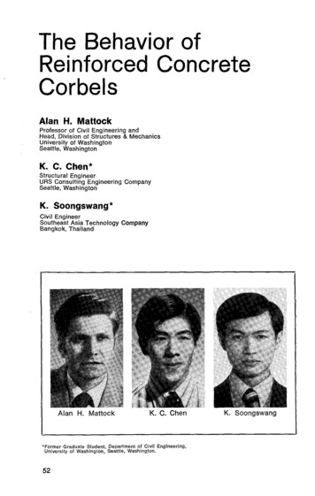
Load from Precast Concrete SlabFloor load w kg/sq.mSTributary area 0.5SL sq.mLoad on beam 0.5wSL kg/mLExample: CPAC Hollow Core Slab HC100100 mm600 mmSLAB WEIGHT296KG/M2PC WIRE6 4MM.SPAN4M.LIVE LOAD300KG/M2w ? kg/mL : Beam span4m
& ก ก3 (Live Load)Floor LoadsSnow and Ice: 50 - 200 kg/sq.m.Traffic Load & Pedestrian Load for BridgesImpact LoadsLateral Loads: Wind & Earthquake & ก ก 3 6& ก ก 6 ( . . 2527) . . . . . 2522 !" # " %& (1) '#" (#)* '#ก (kg/m2)30(2) ก ก 100(3) ก ! "#150(4) %&" 'ก%&" () ก ) ก % # % * , - ., 200(5) ! ก 2500 (6) (ก) 2-) 3 4" , %&" 'ก%&" () ก 2-) 3# "- "- % * (,) & )4 - , ) ก % # ! ก % *0 300300
& ก ก 3 6& ( 0 )ก ก 6 ( . . 2527) . . . . . 2522'#" (#)* '#ก (kg/m2) !" # " %& (7) (ก) - 7 *) # # 8 7 *) # 4 ( # # 9 ก: & 3 9 ก 3(,) & )4 - , 2-) 3 # "- "- % * (8) (ก) - ก - -08 2 3 9 3 ก # -# 3 ก: ก % * (,) & )4 - , - 7 *) # 7 *) # # 8 # % * # (9) ก: , # # 400(10) 9 ก: & ก 7 4800500500500600Wind Loads ก * ก 0 ! 1 ' 23103(ก * # 4 3# ก53ก 65 q 0 .5 ρ V2ASCE 7-98q 0.00483 K V 2 7 q stagnation pressure 3# (กก./ .2)V basic wind speed 8 7)#9 # 3 !: 10 (ก ./ .)K ก ?!* ' !: 7# " ก 10
. . . . . 2522WIND DIRECTION'#" ( (กก./ . .) ก"4 1010 h 2020 h 40# กก"4 40508012016030 mLeeward side !: ( )20 mWindwardsideStep wind loading10 m0m 19 ก ก ก ก! "# " ก %ก& " ก '( ' ' (' " ! ' " () ก ก (1) ' '/0 (2) 7 '& ก ' '/0 (3) '& ก ' '/0 ก ก ก 000(4) '& ก ' '/0 (5) '& ก ' '/0 (6) '& ก ' '/0 102030(7) ก '& ก ' '/0 (8) &#' '& ก ' '/0 " 4050 8 ) % ) % %' %' 8989:; & 9 %" ก & ' ก# " &ก " 9' ก %ก& "# " %ก
aci 318Building Code Requirements forStructural Concrete (ACI318-XX)and Commentary (ACI318R-XX)Early 1900s: WSD was mainly used.ACI 318-56: USD was first introduced.ACI 318-63: Treated WSD and USD on equal basis.ACI 318-71: Based entirely on strength approach (USD)WSD was small part called Alternate DesignMethod (ADM).ACI 318-77: ADM moved to Appendix AUSD was called Strength Design Method.aci 318Building Code Requirements forStructural Concrete (ACI318-XX)and Commentary (ACI318R-XX)ACI 318-83: ADM moved to Appendix BACI 318-89: ADM back to Appendix AACI 318-95: Unified Design was introduced in Appendix BACI 318-99: Limit State at Failure Approach was introducedACI 318-02: Change load factor to 1.2DL 1.6LLACI 318-05ACI 318-08
Reinforced ConcreteDesign MethodsWorking Stress Design(WSD)Ultimate Strength Design(USD)Limit State Design(LSD)Performance-based Design(PBD)#7 0 8 (Working Stress Design : WSD)ACI: Alternate Design Method- Design under service load condition- Apply F.S. to strength of materials forallowable stress level FaStress fromservice loadConcrete:Allowable stressFaFa 0.45f’c (ACI and " .), 0.375 f’c ( . . .Steel:Fa 0.50Fy" # 2522)
Disadvantages of WSD:- Not account for the variability of the resistancesand loads- Lack of any knowledge of the level of saftyF.S. is not known explicitly- Inability to deal with groups of loads where one loadincreases at a rate different from that of the others.#7ก (Strength Design Method : SDM) #* ก, - . Ultimate Stress Design (USD)- Factored load condition Structure is about to fail(Ultimate load /, ก( กDesign Strength - . )Required Strength (U)- Apply F.S. in design via:- Load factors ( 1.0)- Strength reduction factors ( 1.0)
Load FactorsRequired Strength (U) Load Factors Service load Factored Load ก ก Dead Load Factor 1.4Live Load Factor 1.7Factored Load 1.4 DL 1.7 LLService Load DL LLFactored Load CombinationsGeneral:U 1.4 DL 1.7 LLWind Load:U 0.75(1.4 DL 1.7 LL 1.7W)U 1.05DL 1.275WLateral Earth Pressure:U 1.4 DL 1.7 LL 1.7HU 0.9DL 1.7H
Strength Reduction FactorsNominal Strength (N) Strength of a member calculated usingStrength Design Method.Strength Reduction Factor factor that account for(1) Variations in material strengths and dimensions(2) Inaccuracies in the design equations(3) Degree of ductility and required reliability of member(4) Importance of member in the structureStrength reduction factor (φφ) :Bendingφ 0.90Shear and Torsionφ 0.85Compressionφ 0.70 or 0.75Load Transfer in StructureSnow, Rain, Windand Construction loadFloor loadsRoof Dead loadSlab Dead loadBeam Dead loadWind loadEarthquakeColumn Dead loadSoilFoundationWall load
Reinforced Concrete DesignBending in Beam 1 Floor Framing System Load Transferred to Beam from Slab ACI Moment
ACI318-08,American Concrete Institute, 2005. TA444 N38 2009 TA683.2 W53 2009. TA683.2 N55 2004 TA683.2 H365 2005 TA683.2 M39 2009 TA683.2 R48 2008. Course Objectives More than just trial and error, design is based on built up experience as well as a solid background in analysis and an understanding of the parameters affecting a good design solution. ก ก ก ก ˇˆ ˆ ˆ ˇ ก .