Transcription
APPLICATION OF SAP2000: ANALYSIS OF A WARREN TRUSS BRIDGEBy Ait Elmouden Abdellah LaGuardia Community College 31-10 Thomson Ave. Long Island City, NY 11101
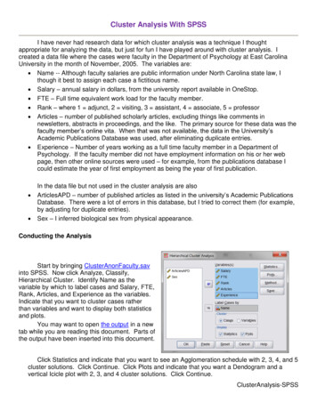
Problem statementPerform the structural analysis of a steel truss bridge that spans a total distance of 63 ft. Thetruss bridge consists of two parallel trusses and the truss configuration is given in the figurebelow. The lower chords of the trusses support the roadway which in turn carries the car andtruck traffic. The object of this analysis is to calculate the internal forces in each memberof the bridge under the effect of the weight of the bridge and roadway (the dead load) andthe weight of the vehicles (the live loads) that are likely to cross the bridge. It is hereinassumed that the bridge carries two lanes of vehicle traffic. Make a first estimate of theinternal forces in each truss member under regular truck traffic. The analysis must beperformed using the SAP2000 package. Use the simplifying assumptions given below toanalyze the four-bay Warren truss bridge shown in Fig 1.AssumptionsThe bridge is supposed to carry its dead load (that is, the weight of the steel members and theweight of the roadway), as well as the live load (that is, the weight of the cars and trucks)that will cross over it. In order to simplify the analysis process, it is assumed that the liveload can be represented by the truck configuration shown below in Fig 1. The effect of thistruck is assumed to model the effect of the heaviest trucks that are expected to cross thebridge in its lifetime.By Ait Elmouden Abdellah LaGuardia Community College 31-10 Thomson Ave. Long Island City, NY 11101
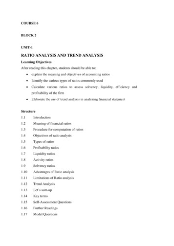
Fig 1: Four-Bay Warren Truss Bridge & Design TruckAssume that the bridge is 26 ft wide with a two-foot curb on each side and that the roadwaycarries two lanes of traffic. Because the bridge has two parallel trusses, it is herein assumedthat the total load applied on the bridge is divided equally to each truss. That is, each trusswill carry the weight of its members, half the weight of the roadway and one lane of traffic(that is, one truck like the one shown in Fig. 1).When calculating the weight of the roadway, assume that it is formed by one concrete deckwith an 8-inch thickness. Concrete weighs 150 lb/ft3 and the weight of concrete must becounted as part of the applied load. Since the roadway is carried by the lower chords of thetruss, the weight of the roadway will have to be divided to each joint of the lower chord.At this stage assume that each of the steel truss members has cross sectional area A 2Q in2and the modulus of elasticity of the steel is E 29,000,000 lb/in2. Steel weighs 490 lb/ft3.The weight of each member will be assumed to be equally divided between the two joints ateach end of the member8inFig 2 Concrete DeckStep 1: Define Model Geometry-The first step when you start SAP2000 is to start A New Model under the File menu.By Ait Elmouden Abdellah LaGuardia Community College 31-10 Thomson Ave. Long Island City, NY 11101
-Basic Units: If you are starting a new model, choose the Initialize Model fromdefaults with Units you want to use (Fig3). The units used to start a model become thebasic units for that model. Set the units to lb-ft. Then, select from the template menuthe 2D Trusses template to start.-From the 2D Trusses template, set the number of divisions to 4. Enter a height of13.64 ft, a division length of 15.75. Leave the section properties as default, and makesure that the restraints box on the lower left corner is checked.-Once you click the OK button, the window will split in two different views of thetruss: A 3-D and an X-Z plane view. Click inside the 3-D window. From the top menuclick on Select - Select - All, or use the command Ctrl A, that will select theentire truss as well.By Ait Elmouden Abdellah LaGuardia Community College 31-10 Thomson Ave. Long Island City, NY 11101
-Now the truss elements will appear in dotted lines. From the Edit menu, select theoption Replicate, or use the command Ctrl R to get the Replicate dialog box. Whenthe box opens, select the linear tab, and enter a value of 26 feet on the dy box. Leave1 for the box Number and click OK.By Ait Elmouden Abdellah LaGuardia Community College 31-10 Thomson Ave. Long Island City, NY 11101
The truss will replicate in the 3-D window. Now select the opposite window by clicking onit, and then go to the View menu and select the 2-D view. The 2-D View box will show youthe different planes available. Select the X-Y plane, and make sure that the Z value is set to13.64 ft, which is the top of the trusses.By Ait Elmouden Abdellah LaGuardia Community College 31-10 Thomson Ave. Long Island City, NY 11101
From the Draw menu, select Draw Frame/Cable/Tendon (or selected from the left tool bar).The pointer of the mouse will convert into a pointing down arrow. Click on the top nodesof the truss to draw the top chord members of the truss as it is show in the pictures below,joining the top nodes of the truss.Draw the bottom cables of the bridge: Again from the View menu, select the 2-D view.This time, set the X-Y plane distance to 0 to reach the bottom nodes in the truss. Repeat theprocess performed for the top nodes. Joint the nodes drawing frame elements from the Drawmenu. The end result should look similar to the picture that follows.By Ait Elmouden Abdellah LaGuardia Community College 31-10 Thomson Ave. Long Island City, NY 11101
Step 2: Defining Structural SectionsAt this stage assume that cross sectional area, A 20 in2, is the same for each steel member.From the define menu, choose Section Properties - Frame Sections. This will open theDefine Frame Properties window:- Click on the Import New Property.- From Frame section property type list select Steel- From steel section Click I/Wide flange-By Ait Elmouden Abdellah LaGuardia Community College 31-10 Thomson Ave. Long Island City, NY 11101
- From the Section Property File windows select SECTIONS8.PRO (last file in thelist)By Ait Elmouden Abdellah LaGuardia Community College 31-10 Thomson Ave. Long Island City, NY 11101
-Click Material (1), then new Material (2)Select Material as steel from Material type (3)Select ASTM 36 from Standard (A36 steel is a standard steel and a commonstructural steel in the United States)-- Click OK, then OK again- Select A36 from Material and W10x68 From-Select Section to ImportClick OK, then OK againNote: W10x68 is the Designation of Wide flange 20” cross sectionarea. For More type of S or W I-beams visit el-beam.htmlBy Ait Elmouden Abdellah LaGuardia Community College 31-10 Thomson Ave. Long Island City, NY 11101
Step 3: Assigning a Structural SectionsNow we will assign the W10x68 I-beam (20” cross section) to our bridge:- Press Ctrl A to select the whole bridge- Go to Assign/Frame/Frame Section- From the Frame property window select W10x68 then press OKNow we finished designing our bridge frame and assigning a 20in cross section area to steelmember. Next step will be adding the concrete deck.By Ait Elmouden Abdellah LaGuardia Community College 31-10 Thomson Ave. Long Island City, NY 11101
Step 4: Defining and assigning the roadway (Concrete Deck)Roadway property:- Concrete deck thickness 8in- Concrete weights 150 lb/ft3- The roadway will have to be divided to each joint of the lower chordIn SAP200:- From the View menu, select the 2-D view. This time, set the X-Y plane distance to 0to reach the bottom nodes in the truss.a- Define the concrete area :--Go to Define/Section property/Area sectionFrom the Select Section Type to Add Select ShellClick Add new SectionType DECK into the section name edit boxVerify that the Material Name is set to 4000Psiin the Material area. Clicking button willdisplay the define materials from where materialProperties may be altered or added.Set the Thickness (both Membrane and Bending) to8in (make sure you add “in” after 8).Click the OK button then click the OK to completeThe Deck definitionBy Ait Elmouden Abdellah LaGuardia Community College 31-10 Thomson Ave. Long Island City, NY 11101
Note: you can modify you sections property any time you wantb- Assign the concrete area :- From the View menu, select the 2-D view. This time, set the X-Y plane distance to 0-to reach the bottom nodes in the truss.Select Draw Rectangular Area from the left tool bar, then select the Deck sectionfrom Properties of Object windowBy Ait Elmouden Abdellah LaGuardia Community College 31-10 Thomson Ave. Long Island City, NY 11101
-Draw the rectangle area following the figure below (The drawn concrete rectanglewill be highlight in red)-Press Esc to exit the Tool and go back to selection modeMesh the Area Object-Click anywhere on the area object to display the Object ModelGo to Edit/Edit Area/Divide AreaSelect the Mesh Area Based On Points On Area Edges option.By Ait Elmouden Abdellah LaGuardia Community College 31-10 Thomson Ave. Long Island City, NY 11101
The roadway (Area Object) is now meshed. (Click inside each box to check)To better view the deck addition, click the set Display Options button, or go to the viewmenu Set Display Option command (Or press Clrl W). When the form appears, check FillObjects box and Apply to All Windows check box as shown in bellow figureBy Ait Elmouden Abdellah LaGuardia Community College 31-10 Thomson Ave. Long Island City, NY 11101
-Click OkStep 5: Define Load Cases (Live Load)The load used in this tutorial consists of dead and live static load acting in the gravitydirection.For this project, assume that dead consists of the self-weight of the bridge plus an additionallive load (the weight trucks).Dead load the weight of the steel members the weight of the roadwayBy Ait Elmouden Abdellah LaGuardia Community College 31-10 Thomson Ave. Long Island City, NY 11101
Assign Area Stiffness ModifiersIn this step, the membrane properties of the Area object is modified to prohibit the deck fromacting as flange for the bottom chords of the trusses. Make sure that X-Y Plane @ Z 0 viewis still active, and that the program is in the select mode.A- Click anywhere on the area object to select the deck.B- Click the Assign menu Area Area Stifness Modifiers command to access theproperty/Stiffness Modification Factors from shown in Figue.C- Type 0 in the Membrane f11 Modifier edit boxD- Type 0 in the Membrane f22 Modifier edit boxAssign Joints Load (Live load)When the cars and trucks move across the bridge, they normally produce dynamicoscillations of the bridge structure. This dynamic oscillation will in turn produce forces ineach member that are higher than the forces obtained if the loads are statically applied. Theseadditional dynamic forces can be modeled using a dynamic amplification factor or impactfactor. It is herein assumed that the impact factor is equal to 0.27 times the truck load. Thisdynamic amplification load should be added to the total truck load.By Ait Elmouden Abdellah LaGuardia Community College 31-10 Thomson Ave. Long Island City, NY 11101
The impact factor is computed as a percentage increase in vehicle live load stress.Live load without addition of the Impact factorLive load after addition of the Impact factorBack Wheel32000 lb?Middle32000 lb?Front Wheel8000 lb?Calculate the new loads after adding the impact factor- In SAP2000 go to Define menu load pattern- Add the seven cases and make sure you choose Live for load type and leave SelfWeight Multiplier set as 0 for the live loads.Note that Self Weight Multiplier is set to 1 for default case (DEAD). This indicates that thisload case will automatically include 1.0 times the self-weight of all members.By Ait Elmouden Abdellah LaGuardia Community College 31-10 Thomson Ave. Long Island City, NY 11101
Case 1:-Click the pointe tool icon. Select the first two lower cord jointsBy Ait Elmouden Abdellah LaGuardia Community College 31-10 Thomson Ave. Long Island City, NY 11101
Note: It is herein assumed that the live load applied on the bridge is divided equally to eachtruss.- Go to Assign Joint Loads Forces- Select CASE1 for Load Pattern Name- Add the value of the front wheel load in the Load edit boxRemember that the Gravity Direction is in the negative Global Z direction-Click OKCase 2:Now we’ll apply load in four joints (front wheels load and middle wheels load)- Select the second two joints only, then go to Assign Joint Loads Forces- This time select CASE2 for Load Pattern Name- Add the value of front wheel load, then press OK- Next select the first two joints only, then go to Assign Joint Loads Forces- Make sure you are selecting the same Load Pattern Name CASE2- Add the value of the middle wheel load in the Load edit box, Then press OKBy Ait Elmouden Abdellah LaGuardia Community College 31-10 Thomson Ave. Long Island City, NY 11101
Continue with the other cases by following the same steps. Make sure you choose the rightCASE from Load Pattern Name before assigning the loadsYou can display the Load Pattern by going to Display Show Load Assigns JointBy Ait Elmouden Abdellah LaGuardia Community College 31-10 Thomson Ave. Long Island City, NY 11101
Then select the case Load Pattern Name.By Ait Elmouden Abdellah LaGuardia Community College 31-10 Thomson Ave. Long Island City, NY 11101
Step 6: Run the AnalysisIn this Step, the analysis model will be viewed and the analysis will be runClick the Analyze menu Run Analysis command or the Run AnalysisAnalysis Cases to Run form as shown bellow-to access the SetSelect MODAL from the Case Name list.Click the Run/do Not Run Case button to set the action for MODAL to Do Not Run, aswe intend to run only a static analysisClick run Now buttonThe program will create the analysis model from the object-based SAP2000 model, an willsoon display an analysis window. Data will scroll in this window as the program run theanalysis. This information may be accessed at a later time by going to the File menu ShowInput/Output Text Files command and selection the file with .Log extensionBy Ait Elmouden Abdellah LaGuardia Community College 31-10 Thomson Ave. Long Island City, NY 11101
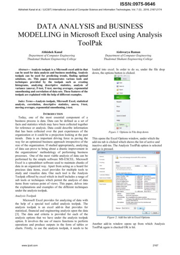
Step 10: Graphically Review the Analysis ResultsIn this Step, the analysis results will be reviewed using graphical presentation of the results.-Select the XZ plan-Click the show Forces/Stresses Frames/Cables button, or the Display menu show Forces/Stresses Frames Cables command to bring up the Member ForceDiagram for Frames (You can also press F8 for a quick access)Select CASE2 / Combo Name Drop-down listSelect the Axial Force option.Select the Auto option under the Scaling areaSelect the Fill Diagram optionClick OK button to generate the axial force diagram shown in figure-Fill Diagram Option: Blue: Tension Red: CompressionShow Values on Diagram optionBy Ait Elmouden Abdellah LaGuardia Community College 31-10 Thomson Ave. Long Island City, NY 11101
Designing the structural members and checking the safety of a design.In This Step, the steel frame members of the trusses will be designed.Not that the analysis should be run before completing the following action items- Click the Design menu Steel Frame Design Start Design/Check of Structurecommand or the Start Steel Design/Check of Structurebutton, to start thesteel frame process.When the design is complete, the selected sizes and stress ratios are displayed on the model.The goal is to repeat the analysis and design process until the analysis and design sections forthe truss are all the same.Note that when the bridge is reanalyzed, SAP2000 will use the current design sections, asnew analysis sections for the next analysis run. You will need to optimize you design bychanging the cross section area of the frame steel, by following the same procedure in Step 2By Ait Elmouden Abdellah LaGuardia Community College 31-10 Thomson Ave. Long Island City, NY 11101
Notes for the design and analysis of the Truss BridgePart A –Procedure:Create an EXCEL table for listing all the members. EXAMPLEMember#COMBO. FORCE (DSLTL4)𝐹𝑂𝑅𝐶𝐸𝐴 𝑚𝑖𝑛 ()𝜎𝐴𝐿𝐿Optimum 𝐴𝑂𝑃 A min i123 Note:DSTL4 (All cases ) Dead Load. To Select DSTL4 Consider the type of force (tension or Compression to select your 𝑖 (Cross section areaincrement).Go to the Steel Sections website (see lbeam.html) and you the 𝐴𝑜𝑝 value to find the cross section Designation (e.g. W10x68 for20𝑖𝑛2𝐶𝑟𝑜𝑠𝑠 𝑆𝑒𝑐𝑡𝑖𝑜𝑛).Select the member that you want to change the cross section then follow step 3 in the tutorialto assign it.Check the safety of a design again and make sure your member is optimum in terms of cost andnot overstressed (green Color):Part B – Cost analysisSteel cost 560 per tonConcrete cost 50 per cubic yardCalculate only the material cost for the steel members and roadway (neglect connections andLabor costs)Part C – Group Report - (format similar to lab reports). Include all concepts andCost analysis: Use the excel file provided to calculate the costPart D – Prototype building and testing (bridge model). Material will be provided
The load used in this tutorial consists of dead and live static load acting in the gravity direction. For this project, assume that dead consists of the self-weight of the bridge plus an additional live load (the weight trucks). Dead load th