Transcription
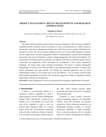
Recent Developments in Profiled-Edge Lamination Diesfor Sheet Metal FormingDaniel F. Walczyk l , David E. HardeIntroduction:The Profiled-Edo-e Lamination (PEL) method was developed by the Walczyk and Hardt [1]as an improvement ov the current ethod of stacking and bonding cont?ure lamin tions interms of the lead-time and cost of toolIng development for sheet metal fOfIlling dIes. It IS also aviable alternative to conventional CNC-machining of such dies. In pursuit of successfulcommercial realization of the PEL method in industry, this paper discusses several important issuesincluding: the origin of this method and advantages over other tooling techniques the general procedure for creating PEL machining instructions determining the geometric error introduced by the straight bevel approximation the propensity for PEL die delamination from high forming loads methods for cutting bevels into die laminations and the machinery needed for PEL die fabrication.Future research and developmental work on the PEL die method will also be outlined.I. Background on the PEL Die Method:Using a laminated construction for sheet metal forming dies is a relatively new idea.Kunieda and Nakagawa successfully created a sheet metal forming die made of horizontallyoriented laminations by slicing up a CAD model of the 3-D forming surface and using the resultingdata to CNC laser-cut the required contours out of sheet material [2]. The contoured laminationswere secured to one another by a combination of cementing with adhesives, clamping with bolts,and laser-welding the edges. Nakagawa et al. formed a solid tool out of stacked laminations bydiffusion-bonding the laser-cut laminations together [3]. Since the lamination edges were cutnormal to the surface and not beveled, the forming surface of the resulting dies had a steppedprofile and thus needed to be CNC-machined with finishing cuts, ground, and polished in order toachieve the necessary smoothness. Some industries completely avoid this secondary smoothingoperation used to remove the stepped profile by filling in the steps with epoxy or some other toughmaterial [4].Weaver was granted a patent for a laminated tooling with the contours machined into eachlamination using beveled edges and not just normal cuts [5]. This change in the art obviates asmoothing operation and only requires a grinding and polishing operation as shown in Figure 1a.The smoothing operation also becomes unnecessary as the laminations get very thin and theresulting steps between laminations are negligible. For instance, LOM can create a forming die forlow force forming that has nearly smooth surfaces since laminations are as thin as 0.05 mm. Thebiggest limitation with current LOM paper/adhesive models is that they have low compressivestrength (26 MPa). This is one-fifth the compressive strength of the cast epoxy (140 MPa) that isused in forming dies. Other materials (e.g. ceramic & metal tape) for LOM models are currentlybeing developed that may take higher compressive loads.As previously mentioned, Walczyk and Hardt recently introduced the PEL method ofconstructing sheet metal forming dies [1). As seen in Figure 1b, a PEL die generally comprises aI Assistant Professor, Department of Mechanical Engineering, Aeronautical Engineering & Mechanics, RensselaerPolytechnic Institute, Troy, NY.2 Professor, Department of Mechanical Engineering, Massachusetts Institute of Technology, Cambridge, MA.215
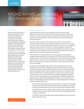
plurality of die lamination members, each die lamination member being substantially planar andeach being disposed in a vertical plane and stacked together side-by-side in an array. The top edgeof each die lamination is simultaneously profiled and beveled in such a way as to approximate asegment of the intended die surface. Specifically, this top edge is continuous in the y-direction andapproximated in the x-direction. The die lamination members may be held together in a stackedarray by any suitable means, but preferably with a clamping frame as shown in Figure lb. Acommon registration corner and the bottom edge of each lamination allows for easy and uniformregistration in the clamping frame. One or more holes uniformly positioned in the sides of eachlamination allows the whole array to be clamped so that no adhesive or other means of holding thearray of die lamination members together is required. If the shape of the forming surface has to bechange during the die development, the die laminations can easily be separated for re-machining toupdate the die shape. The PEL die can be made into a solid die apart from this process by suitablemeans (e.g. diffusion bonding) if needed or desired. Generally at least a portion of the dielamination members have a continuously changing beveled top edge. When placed together in avertical stacked array, the top edges of the die lamination members, in the aggregate, form the topsurface of the die. The advantages that a PEL array construction has over the contoured laminationstack shown in Figure 1a is summarized in table 1.'.!-.Z 38Z "Y"''''''' o--.r:1.,,50. ::.::.-:.- .a)b)Figure 1 - a) Stack of contoured, beveled laminations (Weaver Die) andb) an array of Profiled-Edge Laminations.-T a hie 1 Companson 0 fl arrunatedd'Ie constructionsStack of Contoured LaminationsArray of Profiled-Edge LaminationsDifficult to automate the handling of laminations duringcutting.Difficult to register laminations during die assembly.Difficult to secure lamination stack into a ri id tool.Typically, laminations need to be permanently secured.Reshaoing of die surface requires CNC-machining.Laminations can slide past the profiled-edge cuttingmeans since only top edge is cut.Laminations are easily registered with a base plate and anedge guide.Lamination only needs to be clamped from the side.Unclamped laminations can be individually recut to newdie shape.II. Creating PEL Machining Instructions from a CAD Model:The first step in the process of creating a PEL die consists of creating a 3-dimensionalmodel of the die's fonning surface. The surface model may be created by a die designer usingCAD software; or by a locus of surface coordinates defined by an iteration of a closed-loop controlalgorithm, an FEA model of the die, or a reverse engineering scan from a coordinate measuringmachine. The details of extracting the PEL machining instructions from a surface model of a dieare beyond the scope of this paper. However, to illustrate the data manipulation process required,the general procedure of using a CAD surface model for this purpose will be discussed.The intersection of a 3-dimensional CAD surface model and a Y-Z cutting plane situated onthe X-axis at a certain point is a 2-dimensional curve. Furthermore, if the Y-Z plane is216
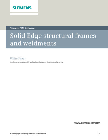
repositioned along the X-axis by constant increments such as 1 rom, the collection of curvesproduced by each of the same plane/surface intersections will approximate the shape of the original3-D surface. The algorithms developed by Phillips et al. and Bobrow for determining theintersection of two arbitrary surfaces (analytic or parametric) can be used [6,7]. The true 3-Dsurface between two adjacent curves can be approximated by connecting them with a bevel. Thisconnecting bevel constitutes the profiled-edge of each PEL die lamination. The reader will notethat the approximation of the 3-D surface gets better as the curves get closer together, i.e. as the xincrement decreases. This collection of curves serves as the machining database for creating a PELdie with the desired forming surface.Anyone of several cutting methods (e.g. laser cutting, machining with an endmill, abrasivewaterjet cutting, plasma-arc cutting) can be used to create the bevels into the top edges of the dielaminations. These methods will be discussed in more detail in a later section. With whatevermethod is used, the data needed for cutting the compound bevels is the position point P 1 on thenearside of the lamination with coordinates (x 1,Y 1,Z1) and a unit directional vectorV VI . i V2 . j V3 . k or just written as (V l' V 2' V 3)' As shown in Figure 2a, the vectorcomponents ofV defined by PI and P 2 (coordinates x2,y2,Z2) areVI x2 -XlIVItL IV!'V2 IVIY2 -YIZ2 -ZIIVI ' and V3 IVI .22(I)1JZ.where: [tt (Y2 -yd (Z2 -zdPoint PI is easy to determine because Xl and YI will be prescribed and ZI is explicitly defined by thenearside intersection curve (see Figure 2a). PointP2 is harder to define since there is no particularone associated with the defined point Pl' To determine P2, an iterative procedure which minimizesthe geometric error introduced by the straight bevel approximation is required. When P? isdetermined then the bevel cutting head will only require translation along the Y and Z-axes, i.e xis kept constant, and rotation about the two orthogonal axes.PThere are many forming dies used in industry for such processes as stretch forming andrubber forming that only have mild curvatures and low draws. For these types of die shapes,reasonable die shape fidelity, i.e. small deviations of the machined shape from the desired CADshape, can be achieved even if the bevel cutting head is only allowed to rotate about the Y-axis.This will allow for simple planar beveling but not compound 3-D beveling like that shown inFigure 2. The position point PI and orientation vector V of the bevel cutting head are defined by(XI,yI,ZI) are coordinates (O,V2,V3), respectively.farside "",curveYL.- --.xFigure 2 - Die lamination profiled edge made by 3-D beveling.217
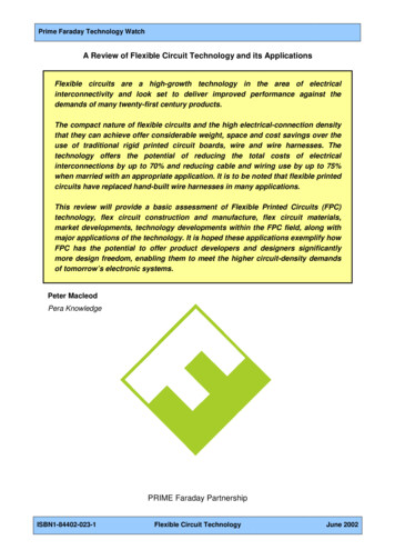
III. Geometric Error Introduced by Straight Bevel Approximation:By observing the X-Z plane cross section of a die lamination in Figure 3, it is evident thatthe straight bevel of the profiled edge will deviate from the desired die surface. During thegrinding and polishing operations on the die surface, this deviation or shape error is increased forconvex cross-sectional profiles, as shown in figure 3a, because of material removal. For the samereason, i.e. material removal, the shape error is decreased for concave cross-sectional profiles asshown in Figure 3b. Therefore, the extent of material removal during the smoothing operationdirectly affects the shape integrity of the forming die. The standard method for determining the dieshape error is to directly measure the surface with a coordinate measuring machine and thencompare that data with the reference CAD shape.unfinisheddie shapeCADshapeunfinishedfinisheddie shapeCADshape' 'a)//interface betweendie laminationsdie laminationsFigure 3 - Shape error due to smoothing of a) convex and b) concave die geometriesInstead of direct measurement, the maximum error introduced by the straight bevel cuttingof the die lamination profiles can be estimated by considering the cross-sectional geometry from theCAD database as shown in Figure 4. The actual cross-sectional curve of the die surface model canbe determined using currently-available CAD software for comparison with the straight bevel. Thetask of extracting this curve is very cumbersome. A simpler way to determine the maximum shapeerror is to estimate the die's cross-sectional curve between points (XpYI) and (x 2,Yz) with aparabola. A parabola is used because it easily curve-fits 2 coordinate points with known slopes.This parabola is defined by bevel end coordinates (xpz l ) and (X 2,Z2)' and the correspondinginstantaneous x-z slopes dz l , dz z . The coordinates and slopes are easily obtainable with manyax zdx lCAD programs (e.g. ProEngineer ). The general equation of a parabola in the X-Z plane is(x - h)2 4· p' (z - k)(2)(x-h)2 -4·p·(z-k)(3)dz?- , an dopens upwards, 'I.e. -dz l dx l dx z. opens downwarddz?1'f Its, 'I.e. -dz l .1'f Itdx ldx 2p parabola's focal length and(h,k) the vertex coordinates.Fitting a parabola to the die lamination cross-section shown in Figure 4 yields the followingsubstitutions into equ. 2;where:hdz} x l -2·p·-;(4)dx land the following substitutions into equ. 3;218
p 2.(dz dz J'jdxj-(5)2dx 2The slope m of the line which passes through points (Xpy 1) and (X 2,y2) is found by the relationm Z2- Zj(6)X 2 -XlThe point (xp,yp) on the parabola with the same slope is found by setting the first derivative ofequ. 2 and equ. 3 equal to m. If the parabola opens upward, then(7)x p h - 2 . P . m and zp k - P . m 2 If the parabola opens downward, thenx p h 2 . P . m and zp k P . m 2.(8)To find the distance e between the line passing through (xj,yj) and (X 2,y2) and the parallel linepassing through (xp,yp)' a line is constructed through (xp,yp) which is perpendicular to the other two lines, i.e. slope .-!.mThis perpendicular line intersects the (xj,yj) and (X 2'Y2) line at point(xg,yg)' The values of this new intersection point are found from the equationsxpm·x I --z zIpXg m(9)Im mThe maximum distance e between the parabola and the straight line representing the bevelrepresents is the largest error. It is calculated with the equatione (xp X g)2 (zp Zg)2(10)If desired, the error estimated with equ. 10 can be expressed as a function of laminationthickness tL so that an optimization procedure for choosing the thicknesses, interface placement,and orientation of the laminations can be implemented. The goal of this procedure would be tominimize the overall bevel approximation I)Figure 4 - Shape error estimation of a beveled die laminationIV. Bevel Cutting Methods For Die LaminationsOnce the intersection curves that define the top profiled-edge bevels of each lamination areextracted from the CAD model, the corresponding die laminations can then be fabricated. Thismachining database can then be used to either cut new die lamination blanks or to recut existing dielaminations into a new shape. Machining bevels into the die lamination edge can be accomplished219
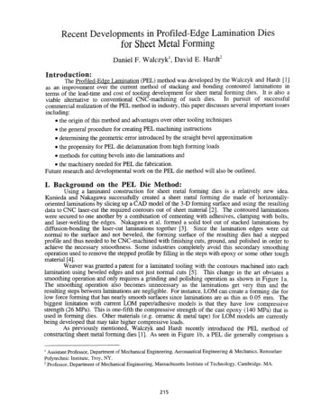
by several methods. As seen in Figure 5a, the flute-edge of a standard endmill mounted in thespindle of a 4 or 5-axis (X, Y, and Z-translation, Y and Z-rotation) CNC milling center can beused to cut bevels into a suitably-fixtured die lamination. This machining method relies on theapplication ofhigh machining forces to make a wide cut in the workpiece. To minimize the amountof material removed while cutting the bevel, a very narrow kerf can be cut into the die laminationusing unconventional machining methods like traveling-wire EDM, abrasive water-jet cutting,plasma-arc cutting, or laser cutting (both CO2 and Nd:YAG) as seen in Figure 5b. Each of thesemethods require CNC-controlled axes that move in X, Y, Z translation, and Y, Z rotation. ;:tating indleEndmilla)b)Figure 5 - Cutting bevels into die laminations by a) flute-edge endmilling andb) by unconventional machining methods.The important characteristics of any bevel cutting method are maximum achievable bevelangle, maximum cutting feedrate (speed), cut surface quality, cutting accuracy, amount of materialremoved, tool wear, extent of metal burring, and machine cost and the effect of material hardnesson cutting speed. Quantifying the performance specifications of each of the aforementioned bevelcutting methods is necessary so that the most suitable one(s) for machining PEL die laminations areidentified.Suitable methods for cutting bevels include machining with the flute-edge of an endmill,abrasive water jet cutting, plasma-arc cutting, and laser cutting. Although wire-cut EDM produceskerfs of excellent quality and accuracy, an extremely slow cutting feedrate makes it impractical forbevel cutting. The other cutting methods were investigated in detail through a series of bevelcutting experiments to determine how rapidly and accurately each one will machine steel PELlaminations. The lamination material used for all cutting experiment was 1.47 mm thick SAE 1010cold drawn steel sheet. Steel was used for the cutting experiments since it is arguably the mostcommon material for sheet metal forming dies [8]. The basis of evaluation for each bevelingmethod will be the quality characteristics of the bevel cut that it makes. The quality characteristicsare defined in figure 6.ex, bevel angle (0· ,30·,60·)Vc max. cutting speedR a surface finish(Effects the timerequired to finish a die)w (Cankerf widthaffccl the smallestachievable geometrical detail)HD (Burrburr heightmust removedbeprior to die assembly)a taper angle(Must be compensated forwith cutting head orientation)Figure 6 - Quality characteristics of a bevel cut.220
The following equipment was used for the bevel cutting experiments: a Cincinnati-Milacron 3-axis machining center with a 6.4 mm diameter 4-fluted carbideendmill. An OMAX JetMachining System with a 0.76 mm cutting nozzle diameter and 80 gritgarnet abrasive, i.e. 0.267 mm average particle size. a Hypertherm HD-1070 HyDefinition Plasma-Arc unit with 02 plasma & shield gas, 130volt DC output voltage and 30 amp output current. a Laserdyne 5-axis, model 780, CNC laser cutting system with a Lumonics JK704Nd: YAG laser (maximum 400 watts of average output power).Further details on all of these cutting experiments can be found in reference [9].Summary ofBevel Cutting Methods:For the purpose of comparing the candidate bevel cutting methods, the bevelingperformance measures (cutting force, maximum fm' maximum a, taper angle, kerf width,machining burr height, and kerf surface finish) of each method, with process parameters set totheir optimal levels, are listed in table 2. Plasma-arc cutting is noticeably absent from this tablesince it became apparent that this method was not suitable for bevel cuts. Bevels at angles up to45 yielded very large tapers ( 10 ) in the kerf, excessive dross (H n 0.9 mm) which was weldedto the metal, and a large Heat Affected Zone (HAZ). The large HAZ caused the cut edge of thelamination to warp slightly. The maximum bevel angle achieved was 60 but the kerf edge closestto the cutting nozzle was consistently obliterated from an over-zealous oxidation (self-burning) ofthe metal during cutting. Consequently, the following comparisons are only made between fluteedge endmilling, AWl cutting and laser cutting: Flute-edge endmilling involves the application of a high cutting force with a cutting toolto remove the unwanted lamination material. The higher cutting forces significantly deflectthe cantilevered portion of a lamination being beveled. AWJ cutting and laser cutting, i.e.non-contact cutting methods, cause negligible deflection to the lamination. All three cutting methods are capable of high cutting speeds but the maximum speed ishighly dependent upon the material composition and hardness with flute-edge endmillingand AWl cutting. The maximum laser cutting fmis only dependent on laser power, i.e.proportional to qlaser' which means that higher cutting rates than that listed in table 2 areachievable. The maximum bevel angle for all three methods is around 80 . The kerf from AWJ cutting has a very large, consistent taper of around 10 for all bevelangles that must be compensated for during bevel cutting. Laser cutting creates only aslight kerf taper. Flute-edge endmilling leaves no appreciable kerf taper unless there issignificant deflection of the lamination and cutting tool during beveling. The width of the kerf affects the smallest radius of curvature achievable for a PEL'sprofiled edge. Of the three beveling methods, laser cutting creates the narrowest kerf. Thekerf from AWl cutting is also narrow but not as much as that cut with a laser. The kerfwidth from endmilling is much larger, i.e. the diameter of the cutting tool.221
Flute-edge endmilling leaves a very large machining burr, especially at larger bevelangles. AWJ cutting and laser cutting, on the other hand, yield much smaller machiningburrs. Laser cutting with a pure oxygen assist gas yields a porous, brittle edge burr (i.e.iron oxide) which is easily removed from the cut lamination without having to grind it off. Flute-edge endmilling yields the smoothest surface finish of all the methods although thefinish deteriorates at higher bevel angles from more machining chatter. AWJ cutting offersthe most consistent surface finish for all bevel angles.Table 2 - Comparison Table of Bevel Cutting Methods. 0 'pltimalParameter S'uSIngethngsCutting MethodFlute-EdgeEndmillingAbrasive WaterJet CuttingSignificant (lamination Small (momentumbends 1-2 mm at high transfer from abrasive)bevel angles)0.46(affected by material0.31 (affected byMaximum fmfor 0 bevel cut (meters/min)hardness andmaterial composition)composition)Cutting ForceMaximum a-l(-L f) 85'Negligible0.44 forkW(max. fmocqlascr)qla r O.3at least 75 80 10 0.70.11 to-2 HD(mm)None6.4 (tool 0)2.8R (J.!m)0.73.4Kerf Taper Angle ew(mm)Nominal 30 BeveltanNd:YAG LaserCutting with HardOptic BeamDeliverytL0.10.04(porous edge burr)4.4Based on the preceding analysis and discussion, the authors rank the suitability, i.e. best toworst, of these three bevel cutting methods for cutting steel laminations as follows:1) Nd:YAG laser cutting because feedrate is only dependent on laser power, tool wear isnon-existent, cutting force is negligible and the kerf is the narrowest of all,2) Abrasive water jet cutting since feedrate is dependent on material hardness and the kerftaper is the largest among the three methods, and3) Flute-edge endmilling since the cutting force, kerf width, edge burr, and feedrate' sdependency on material hardness is the greatest overall.v.Machinery for Fabricating PEL Dies:As with CNC-machining of a sheet metal forming die, the two most importantspecifications of equipment used to fabricate PEL dies are to 1) get as close to near net shape aspossible thereby minimizing the need for a post-grinding or finishing operation and 2) accomplishthis task as fast as possible. The key to meeting these specifications are the correct choice of abevel cutting method, as discussed is the previous section, and the efficient handling of dielaminations during the cutting. There are two options for efficiently cutting PEL die laminations:retrofitting a commercially-available cutting machine or developing a dedicated, stand-alonemachine.For compound beveling of PEL die laminations, a 5-axis machining center (e.g. 3translational & 2 rotational axes) is required to correctly position the cutting nozzle during theprofiling process. Currently, there are numerous 5-axis conventional machining centers, and a fewlaser and AWJ machining centers that can be used to machine compound bevels. Using any of222
these 5-axis machining centers, a die lamination blank must first be vertically secured to themachine's workbed and then the profiled-edge is machined. The die lamination can be handledmanually or the machining center can be retrofitted with an automatic handling mechanism.Five-axis laser machining centers are much more expensive than comparable AWJ or CNCmachines. For example, a Laserdyne Model 780 BeamDirector 5-Axis laser machining centerwith a Lumonics JK704 laser currently sells for around 625K. Other laser machining centersvary in price from 500K to 700K. In contrast, a Cincinnati-Milac o Sabre-lOOO CNC 3-axisvertical machining center retrofitted with a Tsudakoma TTNC-201 tIltmg rotary table that has asimilar work volume as the Laserdyne system sells for around 120K. For 180K, a company anpurchase a Jet Edge model 55-30 AWJ cutting system that's mounted to a 5-axis, robot-controlledgantry table and has a similar work volume as the laser system. With any of these systems, theestimated cost of a custom-built lamination handling mechanism has not been added to their overallcost.Dedicated PEL Die Fabrication Machine:Both conventional CNC and laser machining centers are designed for general industrial useand not optimized for cutting die laminations in terms of speed, cost, and factory floor spacerequired. Taking into account the high cost of commercially available equipment and the addedcost of a custom-built lamination handling mechanism, a dedicated stand-alone machine forfabricating PEL dies is proposed by the authors as a cost-effective alternative to retrofittingcurrently-available 4 and 5-axis cutting machines. This specialized apparatus will be called a DieLamination Profiling (DLP) machine. For industry to embrace the PEL die method, thesemachines will be required to fabricate dies in a rapid and efficient manner. Several machine DLPmachine concepts have already been developed.VI. Propensity for PEL Die Delamination:If the PEL die laminations are bonded together then the composite structure becomes acontinuous die. To keep the PEL die easily re-machinable, the die laminations are simply clampedtogether with a rigid frame as shown in Figure lb. In a clamped configuration, individuallaminations have a propensity to delaminate, i.e. separate from adjacent laminations, by elasticallydeforming or buckling under the high forming loads encountered. As seen in Figure 7a, the dieshape changes when a lamination(s) bends elastically resulting in dimensional changes to the partsformed. For this reason, it is important to investigate the elastic bending and buckling behavior ofa clamped lamination subjected to typical forming loads.Excessive deformation of any of the clamped die laminations beyond a certain maximumvalue, i.e. b ()max' will be considered a die failure. Ideally a PEL die should emulate a continuousdie whose surface deformation is essentially negligible (e.g. 0.01 mm for a steel die). However, amore practical design requirement for PEL dies is to make sure that the dimensions of the formedpart are within the specified tolerances. The maximum deformation value (bmax) of a die laminationis explicitly determined from this requirement.Referring to Figures 7a and 7b, a group of deflected laminations (due to high formingloads) can be roughly modeled as cantilevered Euler beams in a parallel configuration. Thisassumes that the frictional shear forces at the interfaces between adjacent laminations are negligible.The deflection () of a single rectangular lamination (see Figure 8a) can be estimated using therelationb 4· Fbending ( )3where:a lamination heightb lamination widtht lamination thicknessB·b223t(11)
E tensile elastic modulus of the lamination material horizontal component of the lamination's total forming load.By rearranging equation 11, the spring rate k L of the lamination is thenFbendingk b· E (-!.)3L Fbending84a(12)The mode of mechanical failure of a lamination from the vertical component of the formingload F buckling will be some form of buckling behavior. As stated by Timeshenko et aI., " in thecalculation of critical values of forces applied to the middle plane of a plate at which the flat form ofequilibrium becomes unstable and the plate begins to buckle, the same methods as in the case ofcompressed bars can be used" [10]. Therefore, the critical buckling load Fbcritical for the laminationshown in Figure 8a can be estimated using the Euler column buckling formulak·E· b·t 3Fb,critical 12.(13)where:k factor that depends on the end support conditions of lamination.If the lamination can be modeled as a simple cantilever beam then k is 2.47. If the movement ofit's upper edge is restricted horizontally then k is 20.2.The forming forces on a lamination consist of an effective normal load F n and aperpendicular frictional load f.l. F n at the lamination (die) and sheet metal interface where f.l is thefrictional coefficient. These loads are shown in Figure 7. The total forming load F T has a1magnitude of Fn . (1 f.l2)2-. As shown in Figure 8b (vector diagram), FT typically points inwardto the die. This is a desirable situation since convex portions of the laminated die will tend to bepushed together during forming. In terms of F T , the bending and buckling loads areFr .sin(ex -tan -1 f.l) and :By. cos(a - tan -1 f.l), respectively.As an example, let us investigate the bending and buckling propensity of one particularlamination in the male PEL die described in reference [1]. The lamination chosen is located 2.8centimeters in from the edge along the X-axis. It's profiled edge forms half of the upper bendradius for one of the benchmark part side walls. A maximum forming load of 50 kN is predictedby the FEA simulation of the forming process. Since the upper bend radii on the male die takesmost of the total forming load, the estimated maximum normal force that this particular laminationexperiences is approximately 6.0 kN. Additional data on the lamination is a 1.9 cm, b 6.4 cm,tL I.47 mm, E 200 GPa, f.l 0.2 (for greased steel on steel) and a bevel angle 30 . As a resultthe bending and buckling components of the total forming load are 2.0 and 5.8 kN, respectively.Furthermore, the prescribed dimensional tolerance of the benchmark part is 0.1 mm. Since thislamination is backed by 35 adjacent laminations of similar size in the direction of the bending load,the estimated bending deflection is only 0.04 mm according to equation 11. This deflection is wellbelow the die's dimensional tolerance. This simple deflection analysis doesn't even take intoaccount the symmetrical loading on the male die which will tend to counteract the high formingload applied to this sample lamination. Finally, if we assume a worst case buckling scenario wherethe lamination is unsupported on it's top edge, the critical buckling load is 23 kN according toequation 13. This value is well above the maximum above the maximum assumed buckling load of5.8 kN so that buckling will not be a problem.224
Figure 7 - a) Group of die laminations subjected to forming loads andb) modeled as cantilevered Euler beams in a parallel configurationFbucklingFbendino.--I.,./a , FnFTFbuckling'ab)a)Figure 8 - a) a single rectangular die lamination subjected to bending & buckling loads andb) vector diagram of the said loads.Conclusions and Planned Future WorkIn terms of handling laminations during processing, registering and clampin
Using a laminated construction for sheet metal forming dies is a relatively new idea. Kunieda and Nakagawa successfully created a sheet metal forming die made of horizontally oriented laminations by slicing up a CADmodel ofthe 3-Dforming surface and using the resulting datato CNC laser-cutthe requ