Transcription
Manual No: 577013-776TCP/IP Interface ModuleInstallation GuideRevision: D
NoticeVeeder-Root makes no warranty of any kind with regard to this publication, including, but not limited to, theimplied warranties of merchantability and fitness for a particular purpose.Veeder-Root shall not be liable for errors contained herein or for incidental or consequential damages inconnection with the furnishing, performance, or use of this publication.Veeder-Root reserves the right to change system options or features, or the information contained in thispublication.This publication contains proprietary information which is protected by copyright. All rights reserved. No partof this publication may be photocopied, reproduced, or translated to another language without the prior writtenconsent of Veeder-Root.DAMAGE CLAIMS1.Thoroughly examine all components and units as soon as they are received. If damaged, write a completeand detailed description of the damage on the face of the freight bill. The carrier's agent must verify theinspection and sign the description.2.Immediately notify the delivering carrier of damage or loss. This notification may be given either in personor by telephone. Written confirmation must be mailed within 48 hours. Railroads and motor carriers arereluctant to make adjustments for damaged merchandise unless inspected and reported promptly.3.Risk of loss, or damage to merchandise remains with the buyer. It is the buyer's responsibility to file a claimwith the carrier involved.RETURN SHIPPINGFor the parts return procedure, please follow the appropriate instructions in the "General Returned GoodsPolicy" and "Parts Return" pages in the "Policies and Literature" section of the Veeder-Root North AmericanEnvironmental Products price list. Veeder-Root 2004. All rights reserved.
Table of ContentsTable of ContentsIntroductionGeneral .1TCP/IP Interface Requirements .1TCP/IP Kits .1Contractor Certification Requirements .1Related Manuals .2Safety Precautions .2TCP/IP Interface Module InstallationVerifying TCP/IP Interface Module Configuration .3Installing the TCP/IP Interface Module in the Console .4TLS-300/ProPlus Consoles .4TLS-350/ProMax Series Consoles .5TCP/IP Interface Module Communication Setup .7TCP/IP Interface Module Initial ConnectionConnecting to the TCP/IP Interface Module Over a Network .10Connecting to the TCP/IP Interface Module Directly .11TCP/IP Interface Module’s IP Address/Configuration Setup .15Entering the TCP/IP Interface Module’s IP Address.15After Configuring The TCP/IP Module .19TCP/IP Interface Module Configuration Using A Web Browser .19FiguresFigure 1.Figure 2.Figure 3.Figure 4.Figure 5.Figure 6.Figure 7.Figure 8.Figure 9.Figure 10.Figure 11.Figure 12.Figure 13.Figure 14.Figure 15.Figure 16.Figure 17.TCP/IP interface module component locations .3TLS-300/ProPlus Console battery backup switch location .4Installing TCP/IP module into TLS-300/ProPlus Console .5TLS-350/ProMax Series Console battery backup switch location .5TLS-350/ProMax Series TCP/IP module installation .6Installing TCP/IP Module in TLS-350/ProMax Comm Bay Slot 4 .7Network connection .10Locating network connection/activity LEDs .10Direct connect using ethernet crossover cable .11Network Screen .12TCP/IP Properties dialog box .13Local Area Connection Status Screen .13Local Area Connection Properties Screen .14Internet Protocol TCP/IP Properties dialog box .14Telnet Setup Menu .16Web Browser Login .19Web Manager Interface .20i
Table of Contentsii
IntroductionGeneralThis manual contains procedures to install a TCP/IP Interface Module into the following consoles: Veeder-Root TLS-3XX Consoles Red Jacket ProPlus and ProMax ConsolesIf this is a new installation or if site preparation is necessary, refer to the console’s Site Preparation and Installationmanual, or contact your Veeder-Root representative for assistance.TCP/IP Interface RequirementsMinimum system requirements for TCP/IP Interface Module operation are listed below: Console system software: Version 15 or higher - Version 21 or higher is recommended. Network connection to a PC requires a hub. Connecting to a hub requires a straight CAT 5 cable. Direct connection to a laptop requires an ethernet crossover cable. Connection to a LAN or WAN. Knowledge of networking.TCP/IP Kits TLS-300/ProPlus Console Kit (P/N 330020-424):- TCP/IP module (P/N 331871-001)- #4-40 x 0.312” taptite screw - T-10 Torx drive (P/N 510500-414)- Installation Guide (P/N 577013-776) TLS-350/ProMax Console Kit (P/N 330020-425):- TCP/IP module (P/N 331870-001)- Wiring harness (P/N 330584-001)- Installation Guide (P/N 577013-776)Contractor Certification RequirementsVeeder-Root requires the following minimum training certifications for contractors who will install and setup theequipment discussed in this manual:Level 1Contractors holding valid Level 1 Certification are approved to perform wiring and conduit routing,equipment mounting, probe and sensor installation, tank and line preparation, and line leak detectorinstallation.1
TLS RF Console Site Prep & Installation ManualRelated ManualsLevel 2/3 Contractors holding valid Level 2 or 3 Certifications are approved to perform installation checkout,startup, programming and operations training, troubleshooting and servicing for all Veeder-Root TankMonitoring Systems, including Line Leak Detection and associated accessories.Warranty Registrations may only be submitted by selected Distributors.Related Manuals576013-623TLS-3XX/ProPlus/ProMax Series System Setup Manual576013-879TLS-3XX/ProPlus/ProMax Series Consoles Site Prep and Installation GuideSafety PrecautionsThe following safety symbols are used throughout this manual to alert you to important safety hazards andprecautions.OFFEXPLOSIVEFuels and their vapors are extremelyexplosive if ignited.ELECTRICITYHigh voltage exists in, and is supplied to,the device. A potential shock hazard exists.TURN POWER OFFLive power to a device creates apotential shock hazard. Turn Off powerto the device and associated accessories when servicing the unit.READ ALL RELATED MANUALSKnowledge of all related procedures beforeyou begin work is important. Read andunderstand all manuals thoroughly. If youdo not understand a procedure, ask someone who does.WARNINGYou are working with a device in which potentially lethal voltages may bepresent.Death or injury may result if safety precautions are not followed.1. Read all instructions and warnings.2
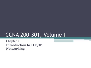
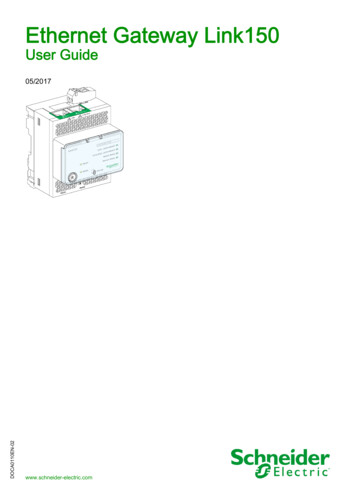
TCP/IP Interface Module InstallationInstallation of the TCP/IP Interface module consists of:1. Verifying the module’s configuration,2. Installing the module in the TLS-300 Console (page 4) or the TLS-350 Console (page 5),3. Setting up the module (page 7), and4. Connecting the module to the local area network (page 15).Verifying TCP/IP Interface Module ConfigurationKey components of the TCP/IP Interface module are shown in Figure 1.IMPORTANT! Write down the ethernet address from the label on the back of the TCP/IP board. Youwill need to enter this number for the TCP/IP board’s hardware address in “TCP/IP InterfaceModule’s IP Address/Configuration Setup” on page 15. Also record the rev of the board as it may beneeded in setup.6781RXGRNJ1TXREDLTRX XPort2500-20-4A-82-54-CDJ2 J3INT CL4RESET3LTRX XPort900-20-4A-82-54-CDXPXXXXXXX-XX Rev. A11Patent PendingXXXXXcab&dim\tcpip2.eps10Figure 1. TCP/IP interface module component locationsLegend for numbered boxes in Figure 11.2.3.4.5.6.7.8.9.End plate for TLS-300/ProPlus console TCP/IP module.RJ-45 Connector (typical both end plates)Reset button access (typical both plates)End plate for TLS-350/ProMax console TCP/IP moduleNetwork connection/activity LEDs (typical both end plates)J1 ConnectorJ2 Jumper - InterruptJ3 Jumper - Chip SelectWrite down the ethernet address from the label on the LTRX XPort module (in this example, 00-20-4A-82-54-CD). Youwill need this address for the TCP/IP module setup.10. Also record the rev number (in this example A11). It may be needed for the TCP/IP module setup.3
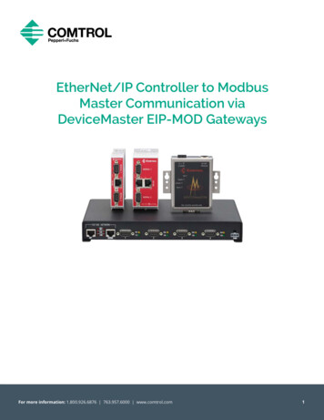
TLS RF Console Site Prep & Installation ManualInstalling the TCP/IP Interface Module in the ConsoleInstalling the TCP/IP Interface Module in the ConsoleTLS-300/PROPLUS CONSOLES1. Open the left door of the console (see Figure 2). Verify that the battery backup switch is in the On position,then turn Off power to the console.2. Remove knockout blank from left bottom of console. Slide in the configured TCP/IP Interface Module until themotherboard connector is snugly seated and the left edge of the module’s bracket is in the notch cutout in theleft side of the console. Attach securing screw from kit (see Figure 3). Leave the console door open.11Legend for numbered boxesin Figure 3S13.Connector for TCP/IPmoduleS21 RELAYRATINGS:FORM CCONTACTS120 VAC,2A Max; or24 VDC,2 A Max.WARNING: TO INSUREINTRINSIC SAFETY,THIS COVER MUSTNOT BE REMOVED.BARRIERGROUNDINPUTRemove knockout blank toinstall TCP/IP module.12 NC1 NORELAY2.CNC2 NOCLACBattery backup switch (S1)shown in ‘On’ position (toleft)OPEN1.1 2 3 4OFFGN32Figure 2. TLS-300/ProPlus Console battery backup switch location4WARNITHIS
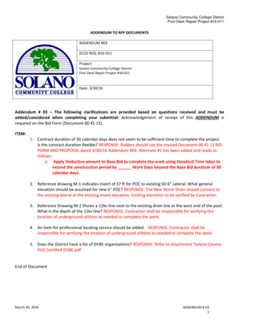
TLS RF Console Site Prep & Installation ManualLegend for numbered boxesin Figure 31.TX (red)2.RX (green)3.Bracket secured in notch4.Remove blank in consolebase for access to module'splug-in connector5.#4-40 x 0.312” taptitescrew - T-10 Torx drive(P/N 510500-414)6.Module bracket7.Module plugs into maleconnector on motherboardInstalling the TCP/IP Interface Module in the Console17263cab&dim\tcpip300.eps45Figure 3. Installing TCP/IP module into TLS-300/ProPlus ConsoleTLS-350/PROMAX SERIES CONSOLESOFF1. Open the left door of the console. Verify that the battery backup switch (SW1) is in the ‘On’ position (seeFigure 4), then turn off power to the console.Legend for numberedbox in Figure 41.Battery backup switch(S1) shown in ‘On’position (up).11 2 3 4OPENSW1SW2cab&dim\tcpip2fig3.epsFigure 4. TLS-350/ProMax Series Console battery backup switch location5
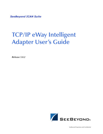
TLS RF Console Site Prep & Installation ManualInstalling the TCP/IP Interface Module in the Console2. Installing the TCP/IP module in slots 1 - 3 (Preferred Location)The TCP/IP module can be installed in any empty slot of the Comm Bay card cage, but the module’s defaultsettings require that it be installed in slots 1 - 3.If your console has a snap connector which secures the cover plate in the card cage, pull it out and lift out thecover plate. If your console has “knockout” cover plates, open the printer door and insert a flat blade screwdriver in the slot provided in the front of the cover plate you are removing and twist it to break the front set ofmetal securing tabs (ref item 2 in Figure 5). Once the front tabs are broken, carefully move the loosened endof the plate up and down until the rear set of securing tabs break. Remove and discard the cover plate. Slidethe module into the open slot until the motherboard connector is snugly seated. Do not apply excessive forcewhen installing the module. With your thumb, push in the black retaining fastener on the end plate until itsnaps into the hole in the card cage.1Legend for numberedboxes in Figure 51.Comm bay card cage2.Comm slot cover plate3.Module slots 1 - 44.24-pin board connector onTCP/IP module1cab&dim\tcpipins.eps423342Figure 5. TLS-350/ProMax Series TCP/IP module installationInstalling the TCP/IP module in slot 4If slots 1 - 3 are in use, or if you want to free up slots 1 - 3 for other modules, the TCP/IP module can be installed in slot 4. To use slot 4, you must move jumpers J2 and J3 on the module onto the 2 top pins, and connect the cable from the kit (P/N 330584-001) to connector J1 on the module and to connector J5 on theconsole’s ECPU board (see Figure 6). Note: if the TCP/IP module is installed in slot 4, the displayedslot number (X) will be 5.3. Verify that the RJ-45 plug in the module’s bracket is accessible through the slot opening in the bottom of theconsole.6
TLS RF Console Site Prep & Installation ManualTCP/IP Interface Module Communication Setup4. When you are finished, make sure any unused slots in the comm cage have a blank end plate installed. Leavethe console door open.Legend for numberedboxes in Figure 51.J2/J3 jumper positions ifinstalling TCP/IP modulein slots 1-3 (defaultpositions)2.Move jumpers J2/J3 onto 2top pins if installing TCP/IP module in slot 43.4.J1 connectorInterconnecting cable fromthe kit (P/N 330584-001)J5 on ECPU board5.2134534J2 J3RXGRNJ11TXREDLTRX XPort00-20-4A-82-54-CDINT CLJ2 J3INT CLJ2 J3RESET2cab&dim\350tcpipins.epsINT CLFigure 6. Installing TCP/IP Module in TLS-350/ProMax Comm Bay Slot 4TCP/IP Interface Module Communication Setup1. Close and secure the console front door. Restore power to the console.2. You will need to know what version software is installed in the console to properly setup the TCP/IP module.Press the front panel MODE key to access Diag Mode. Press FUNCTION key to access System Diagnostic:SYSTEM DIAGNOSTICPRESS STEP TO CONTINUEPress the STEP key to view the software revision level:SOFTWARE REVISION LEVELVERSION XYY.XX7
TLS RF Console Site Prep & Installation ManualTCP/IP Interface Module Communication SetupWhere YY equals the console’s installed software. For example, if the version is 123.02, the software versionis 23.3. Press the front panel MODE key to access the Setup Mode. Press the FUNCTION key to accessCommunications Setup.4. In Communications Setup, press STEP until you see Port Settings, then press ENTER to display the message:COMM BOARD: X (Type)BAUD RATE: 1200If necessary, press the TANK/SENSOR key until you see the message above, where X the slot number inwhich you installed the TCP/IP Interface Module, and Type S-SAT or RS-232. Note: for TLS-350/ProMax consoles only - if the TCP/IP module was installed in slot 4 of the Comm Bay card cage, thedisplayed slot number (X) will be 5.5. Depending on displayed board type (S-SAT or RS-232) and the console’s installed software revision level,select the comm board setup parameters shown in Table 1, Table 2, or Table 3 as applicable.Table 1.- Comm Setup Selections - S-SAT board type & V15 - V20 console softwareComm Setup ParameterSettingBaud Rate9600ParityNONEStop Bit1 STOPData Length8 DATARS-232 END OF MESSAGEDISABLEDTable 2.- Comm Setup Selections - S-SAT board type & V21 & later console softwareComm Setup ParameterSettingBaud Rate9600ParityNONEStop Bit1 STOPData Length8 DATACode (security)DISABLEDDTR NORMAL STATEHIGHRS-232 END OF MESSAGEDISABLED8
TLS RF Console Site Prep & Installation ManualTCP/IP Interface Module Communication SetupTable 3.- Comm Setup Selections - RS-232 board type and V15 & later console softwareComm Setup ParameterSettingBaud Rate9600ParityNONEStop Bit1 STOPData Length8 DATACode (security)DISABLEDRS-232 END OF MESSAGEDISABLED9
TCP/IP Interface Module Initial ConnectionAfter the TCP/IP Interface Module is installed and set up in the console, it can be connected to a PC in two ways: Over a network (LAN, WAN), or DirectlyCONNECTING TO THE TCP/IP INTERFACE MODULE OVER A NETWORK1. Connect the PC to the TCP/IP Interface Module as shown in Figure 7. Insert the RJ-45 plug of the networkCAT 5 cable into the RJ-45 connector in the end plate of the TCP/IP module.Legend For Numbered BoxesIn Figure 71.PC (e.g., back office)2.Plugs into PC Ethernet card3.Ethernet cable4.Hub5.Do not use uplink connector6.Tank Gauge7.Plugs into RJ45 connector inend plate of TCP/IP module43265ALARMWARNING8.POWERT1: PREMIUM UNLEADEDVOLUME 4208ULLAGE 579290% ULLAGE 4792TC VOLUME 4194HEIGHT 41.02WATER VOL 0WATER 0.00TEMP 65.0GALSGALSGALSGALSINCHESGALSINCHESDEG FT1: REGULAR GASOLINEVOLUME 9038ULLAGE 96290% ULLAGE 0TC VOLUME 8950HEIGHT 81.37WATER VOL 28WATER 1.37TEMP 74.9GALSGALSGALSGALSINCHESGALSINCHESDEG Fcab&dim\tcpipnc.eps178Ethernet cableFigure 7. Network connection2. Locate the 2 LEDs on the top edge of the RJ-45 connector on the module’s end plate (see Figure 8).Legend for numbered box inFigure 81.1Network connection/activity LEDscab&dim\tcpip2led.epsFigure 8. Locating network connection/activity LEDs10
TLS RF Console Site Prep & Installation ManualTCP/IP Interface Module Communication SetupDepending on network connection speed, the left or right LED on the top edge of the RJ-45 connector shouldremain ‘On’ when a proper connection is made (ref. Table 4).Table 4.- Network Connection/Activity LED Codes (ref. view in Figure 8)Left LEDRight LEDMeaningOffOffOffSolid amberOffBlinking amberOffSolid greenOffBlinking greenSolid amberOff10Base-T half-duplex linkBlinking amberOff10Base-T half-duplex; activitySolid greenOff10Base-T full-duplex; linkBlinking greenOff10Base-T full-duplex; activityNo link100Base-T half-duplex link100Base-T half-duplex; activity100Base-T full-duplex link100Base-T full-duplex; activityAfter confirming a successful link between the PC and the TCP/IP module, go to “TCP/IP Interface Module’s IPAddress/Configuration Setup” on page 15.CONNECTING TO THE TCP/IP INTERFACE MODULE DIRECTLYConnect the PC to the TCP/IP Interface Module as shown in Figure 9. Insert the RJ-45 plug of the ethernetcrossover cable into the RJ-45 connector in the end plate of the TCP/IP Interface Module. Important! you mustuse an ethernet crossover cable.Legend For Numbered Boxes InFigure 91.Plugs into RJ45 EthernetAdaptor in Laptop2.Laptop3.You MUST use an Ethernetcrossover cable!4.Plugs into RJ45 connector inend plate of TCP/IP module5.5ALARM31Tank GaugeWARNINGPOWERT1: PREMIUM UNLEADEDVOLUME 4208ULLAGE 579290% ULLAGE 4792TC VOLUME 4194HEIGHT 41.02WATER VOL 0WATER 0.00TEMP 65.0GALSGALSGALSGALSINCHESGALSINCHESDEG FT1: REGULAR GASOLINEVOLUME 9038ULLAGE 96290% ULLAGE 0TC VOLUME 8950HEIGHT 81.37WATER VOL 28WATER 1.37TEMP 74.9GALSGALSGALSGALSINCHESGALSINCHESDEG F42consoles\tcpipdc.epsFigure 9. Direct connect using ethernet crossover cableLocate the 2 LEDs on the top edge of the RJ-45 connector on the module’s end plate (see Figure 8 on page 10).11
TLS RF Console Site Prep & Installation ManualTCP/IP Interface Module Communication SetupDepending on the network card installed in the laptop, the left or right LEDs on the top edge of the RJ-45connector should remain ‘On’ when a proper connection is made as shown in Table 4.Before entering the TCP/IP Interface Module’s IP Address enter a static IP Address in your connected laptop. IPAddress setup procedures for both Windows 98 and 2000 are discussed in this section. Windows ME or XPprocedures may be different. Please check those operating system’s manuals to verify their method of entering IPAddresses.Setting Your Laptop’s IP Address for Direct Connect (PC with Windows 98 Operating System)1. Connect your laptop to the TCP/IP card as shown in Figure 9 above. Go to your laptop’s Control Panel folderand doubleclick the ‘Network’ icon to display the Network screen (Figure 10)Figure 10. Network Screen2. In the ‘The following network components are installed.’ window, highlight TCP/IP and then click theProperties button to display the TCP/IP Properties dialog box (Figure 11).12
TLS RF Console Site Prep & Installation ManualTCP/IP Interface Module Communication SetupFigure 11. TCP/IP Properties dialog box3.Click the Use the following IP Address radio button and enter an IP Address and Subnet mask for yourlaptop. You can use an IP address that is one digit off from the customer supplied IP Address you will assignto the console’s TCP/IP Interface Module. For example, if the IP Address for the TCP/IP module is 10.2.1.51,you would enter 10.2.1.50 for the laptop’s IP Address. You also need to enter a Subnet mask. Use the sameSubnet mask that is shown in Figure 11 above (255.255.255.0).Note: Prior to reconnecting your laptop to a network, you will need to select the Obtain an IP address automatically radio button as shown in Figure 11 above.4. You are now ready to enter the TCP/IP Interface Module’s IP Address.5.Proceed to page 15.Setting Your Laptop’s IP Address for Direct Connect (PC with Windows 2000 Operating System)1. Connect your laptop to the TCP/IP module as shown in Figure 9 on page 11 above. Go to your laptop’sControl Panel folder and doubleclick the ‘Network and Dial-up Connections’ icon.2.Select Local Area Connection and the status screen displays (Figure 12).Figure 12. Local Area Connection Status Screen13
TLS RF Console Site Prep & Installation Manual3.TCP/IP Interface Module Communication SetupClick the Properties button and the Local Area Connection Properties screen displays (Figure 13).Figure 13. Local Area Connection Properties Screen4. In the ‘Components checked are used by this connection’ window, highlight Internet Protocol (TCP/IP) andthen click the Properties button to display the Internet Protocol TCP/IP Properties dialog box (Figure 14).Figure 14. Internet Protocol TCP/IP Properties dialog box5.Click the Use the following IP Address radio button and enter an IP Address and Subnet mask for yourlaptop. You can use an IP address that is one digit off from the customer supplied IP Address you will assignto the console’s TCP/IP Interface Module. For example, if the IP Address for the TCP/IP module is 10.2.1.51,you would enter 10.2.1.50 for the laptop’s IP Address. You also need to enter a Subnet mask. Use the sameSubnet mask that is in the example in Figure 14 above (255.255.255.0).Note: Prior to reconnecting your laptop to a network, you will need to select the Obtain an IP address automatically radio button as shown in Figure 14 above.6. You are now ready to enter the TCP/IP Interface Module’s IP Address.14
TLS RF Console Site Prep & Installation ManualTCP/IP Interface Module’s IP Address/Configuration SetupTCP/IP Interface Module’s IP Address/Configuration SetupARP and Telnet are utilities available in Windows operating systems and are used in the TCP/IP addressingprocedure:ARP - ARP is a TCP/IP protocol used to convert an IP address into a physical address (called a DLC address),such as an Ethernet address. A host wishing to obtain a physical address broadcasts an ARP request onto theTCP/IP network. The host on the network that has the IP address in the request then replies with its physicalhardware address. ARP will only work when the console and PC share the same subnet.Telnet - Telnet is a terminal emulation program for TCP/IP networks such as the Internet. The Telnet program runson your computer and connects your PC to a server on the network. You can then enter commands through theTelnet program and they will be executed as if you were entering them directly on the server console. This enablesyou to control the server and communicate with other servers on the network.Port Number- This setting represents the source port number in TCP connections. It is the number that identifiesthe channel for remotely initiating connections. The range of permissable port numbers is 1 - 65535, except for thefollowing reserved port numbers:Reserved Port Numbers1 - 1024999914000-140093070430718NOTE: Do not use any of the reserved port numbers on any version of the TCP/IP board.NOTE: In addition to the IP address configuration instructions provided in this manual, it may also bepossible to use the Lantronix device installer found in the Lantronix website (www.lantronix.com) toconfigure your TCP/IP module’s IP address.ENTERING THE TCP/IP INTERFACE MODULE’S IP ADDRESSWith the PC connected to the TCP/IP Interface Module as discussed above, perform the steps below.1. At the DOS command prompt type (the spaces between words and letters in all entries must be entered asshown or the address will not be successfully assigned):arp -s y.y.y.y 00-20-4a-xx-xx-xx(where y.y.y.y is the IP address of the TCP/IP module (see your network administrator) and 0020-4A-xx-xx-xx is the number from the label on the back of your TCP/IP module [see Figure 1on page 3]).Press Enter.The module’s IP address is added to the ARP table and the screen will return to the DOS command prompt.Type ARP -A at the DOS command prompt and press Enter to view the contents of the ARP table and verifythe presence of the TCP/IP Interface Module’s IP Address.2.At the DOS command prompt type:telnet y.y.y.y 1Press Enter.15
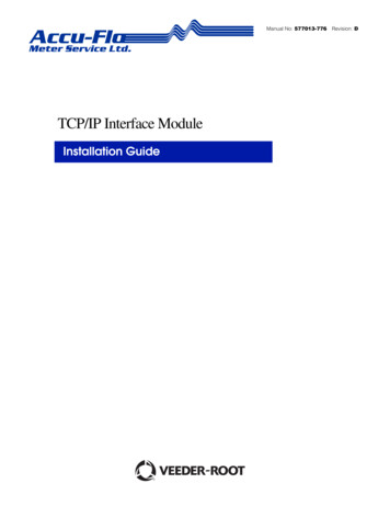
TLS RF Console Site Prep & Installation ManualTCP/IP Interface Module’s IP Address/Configuration SetupThe following message will appear:Connecting to y.y.y.y.could not open a connection to host on port 1. Connect failed or could not open connection to Y.Y.Y.Y.Press OK to close the pop up screen. Close the Telnet screen. The screen will then display the DOS command prompt.3.At the DOS command prompt type:telnet y.y.y.y 9999Press Enter as soon as the Telnet screen appears, press Enter again (NOTE: Telnet screen will timeout if youdo not press Enter within approximately 4 seconds after the Telnet screen appears).The Telnet Setup menu will appear on the screen (see Figure 15). Enter the required TCP/IP Interface Module’s configuration settings shown in Table 5 if your console has software versions 15 - 20, or enter the settings in Table 6 if your console has software versions 21 and later.Note: to accept a setting already in the Telnet Setup menu, press Enter to accept the value andskip to the next selection.4. After completing the TCP/IP Interface Module’s configuration, connect the module to the customer’s network.NOTE: Make changes to server configuration and channel 1 configuration only!Press 9 and Enter to save settings and exit Telnet. A Telnet screen will pop up a warning of lost connection.Press OK and continue.Figure 15. Telnet Setup MenuNOTE: depending on your Telnet configuration, it may be possible to scroll up on the above window and seeadditional settings.16
TLS RF Console Site Prep & Installation ManualTCP/IP Interface Module’s IP Address/Configuration SetupTable 5.- Telnet Setup Menu Settings (Consoles with V15 - 20 Software)Menu SelectionSettingBASIC PARAMETERS - to access, select Change Setup option 0, press EnterIP Address (of console)(get from your network administrator)Gateway(get from your network administrator)Netmask(get from your network administrator)Telnet config password(N)CHANNEL 1 - to access, select Change Setup option 1, press EnterBaud rate9600I/F Mode4CFlow00Port10001Connect ModeC4 (incoming net connection - accept unconditional; startup - manual connection)Remote IP AdrIP address of the computer the console will call on dialout. Example: 010.002.001.0591(Remote) portport of the remote computerDisconn Mode80 (with DTR drop)Flush Mode00Disconn Time (minutes:seconds)01:30 (Note: to enter Disconn time, first enter minutespress Enter, then enter seconds and press Enter)Sendchar100Sendchar2001 When setting up the console to dial out, enter CXXX for receiver phone number - where xxx is thelast set of digits in the Remote IP Address set in Channel 1 of the Telnet Setup menu. For example,if you have a remote IP address of 010.002.001.059, you would enter C059.SECURITY - to access, select Change Setup option 6, press EnterTelnet setup isenabledTFTP download isenabledPort 77FEh isenabledWeb Server isenabledEnhanced password isdisabledSAVE AND EXIT - after making the above selections, select Change Setup option 9,press Enter17
TLS RF Console Site Prep & Installation ManualTCP/IP Interface Module’s IP Address/Configuration SetupTable 6.- Telnet Setup Menu Settings (Consoles with V21 and Later Software)Menu SelectionSettingBASIC PARAMETERS - to access, select Change Setup option 0, press EnterIP Address (of console)(get from your network administrator)Gateway(get from your network administrator)Netmask(get from your network administrator)Telnet config password(N)CHANNEL 1 - to access, select Change Setup option 1, press EnterBaud rate9600I/F Mode4CFlow02Port10001Connect ModeC4 (incoming net connection - accept unconditional; startup- manual connection)Remote IP AdrIP address of the computer the console will call on dialout.Example: 010.002.001.0591(Remote) portport of the remote computerDiscon
Installation Guide TCP/IP Interface Module. Notice Veeder-Root makes no warranty of any kind with regard to this publication, including, but not limited to, the implied warranties