Transcription
Calibration of Bubble Flow MetersSpeaker/Author: M. W. DlaminiCo-authors: D. Jonker, E. P. TarnowNational Metrology Institute of South Africa, Private Bag X34 Lynnwood Ridge 0040,Pretoria, South AfricaE-mail (corresponding author): mdlamini@nmisa.orgThe Gas Flow laboratory of NMISA currently calibrates the majority of gas flowinstrumentation in the range 0,5 ml/min to 50 l/min for the South African industry. This hasled to unacceptably long lead times for calibration slots, which has had an adverse effect onthe industry.In an effort to encourage industry to develop gas flow calibration capacity to improve thissituation, the Gas Flow laboratory of NMISA investigated several calibration methods thatcan be employed to perform bubble flow meter calibrations. These methods include the useof laminar flow meters (LFM) and positive displacement piston provers as referencestandards. Needle valves and Mass Flow Controllers were used to control the gas flow rate. Astandard Bubble Flow Meter Cell (20 ml/min – 6 l/min) was used as the unit under test(UUT) during the measurements.This paper discusses the different calibration methods, compares the results obtained andtheir associated measurement uncertainties.Keywords: thermal mass flow controller, bubble flow meter, piston prover1. IntroductionThe need for stack emission testing and environmental monitoring laboratories to havetheir measuring equipment calibrated by a ISO/IEC 17025 accredited facility has resultedin the NMISA Gas Flow laboratory receiving a vast amount of calibration requests forbubble flow meters (accuracy of 1 % of reading).The NMISA Gas Flow laboratory uses secondary reference standards of accuracy0,15 % to 0,25 % of reading to calibrate gas flow measurement instruments. Thelaboratory is assessing the feasibility of transferring the calibration of bubble flow metersto accredited commercial calibration laboratories. The NMISA Gas Flow laboratory willprovide traceability to these calibration laboratories, if requested.In the following sections the calibration of a bubble flow meter using a commerciallyavailable laminar flow meter system, a positive displacement piston prover and massflow controllers are discussed. These three gas flow reference standards utilisecompletely different principles. The positive displacement piston provers obtainmeasurement traceability from the SI units of time and length.Test and Measurement Conference
2. Flow ControlTo perform gas flow rate measurements at different flow rates, a reliable and stable gasflow rate control device is required. This can be a manually adjustable flow control valveor automated mass flow controller.2.1 Needle ValvesNeedle valves are equipped with a finely threaded stem which fits precisely into a seatover the inlet of the valve[1]. This allows the operator to precisely adjust the flow byrotating the handle. The stem packing provides an air tight seal to atmosphere andsome needle valves are equipped with metal-to-metal seat seal. These devices are agood choice for high temperature applications with lighter and less viscous fluids[1].As the devices have no readout unit, a separate flow meter may be necessary tomonitor the flow rate.2.2 Thermal Mass Flow ControllersThermal mass flow controllers (MFC) are complex mechatronic devices designed tomeasure and control the flow. Thermal mass flow controllers warm up gas passingthrough a capillary stainless steel tube. The change in gas temperature along the gasflow path is then measured by thermal elements coiled around the capillary tube. Themass flow 𝑄𝑀 is given by the equation[2] 𝑇𝑄𝑀 𝐶𝑝𝐾(1)where T is the temperature difference, 𝐶𝑝 is the specific heat capacity of the gas andK is a calibration constant. Thermal mass flow controllers are gas specific since theyuse the specific heat capacity of the calibration gas for flow metering. Therefore,when the process gas differs from the calibration gas, a conversion factor is requiredand is defined as[2]𝑐𝑝1 𝑝1𝐶 𝑐𝑝2 𝑝2(2)where 𝑝𝑖 is the density at normal conditions and the subscripts 1 and 2 representcalibration and process gas, respectively. The electronics of the MFC then open orclose the solenoid valve to increase or decrease the flow.A mass flow controller is itself a mass flow meter as it has to first measure flow,compare it with the input set point and then adjust the solenoid valve.3. Flow Metering3.1 Volumetric Flow MetersVolumetric flow meters measure the time, t t1-t2, it takes for a gas to fill a volumeV. A volumetric flow meter consists of a flow cell and a base unit. The base unithouses the main electronics of the meter. The flow cell houses a flow tube throughwhich a piston rises as the gas fills the tube. Two motion sensors, one at the bottomTest and Measurement Conference
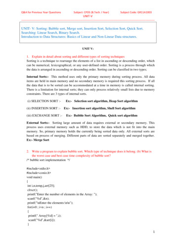
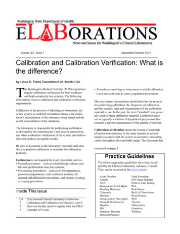
and one at the top of the tube, start and stop a time interval counter as the pistonpasses by. The volumetric flow rate is determined by the equation[3]𝑄𝑣 𝑡𝜋𝑟 2 ℎ𝑉2 𝑡1 𝑡2 𝑡1(3)where r is the flow tube radius and h is the distance between the two motion sensors.Some volumetric flow meters are equipped with barometric pressure transducers andthermometers for instant conversion of volumetric flow to standardised flow. Bubbleflow meters are volumetric meters using soap film instead of a piston and measurevolumetric flow rate only.3.2 Laminar Flow MetersA laminar flow meter is made of a circular cross sectional tube with flow restrictionsinside to create a pressure drop. The pressure drop inside the meter is defined to beproportional to the flow rate in accordance with the Hagen-Poiseuille law for laminarflow pressure drop[5]. The flow rate, Qs, is given by 𝑃𝑄𝑠 𝜋𝑑 4 128µ(4)where d is the inner diameter of the capillary tube, P is the pressure drop and µ is theviscosity of the fluid. The viscosity is a function of the temperature.Laminar flow meters require the Reynolds number (Re) of the flowing fluid to be lessthan 2000 indicating laminar flow conditions are maintained. To increase the range ofthese meters, manufacturers design their laminar flow meters with several capillarytubes to limit Re to less than 2000 in each capillary tube. The total flow rate throughthe meter is given by𝑄 𝑁𝑄𝑠(5)where N is the number of capillary tubes in the meter[5].These flow meters are good to measure low to extremely low flow rates and havelinear calibration and low noise[6]. To minimize errors, these meters must be operatedin a controlled temperature environment as the density of gases varies significantlywith changing temperature[6].4. Bubble Flow Meter Calibration Against a Piston Prover4.1 Calibration SetupPrior to calibration, the instruments were left in the laboratory to achieve thermalequilibrium. The calibration setup is shown in Figure 1 with the reference standardupstream of the bubble flow meter to avoid contamination. The system waspressurized to 200 kPa at a flow rate of 2500 sccm (standard cubic centimetre perminute) and leak checks were performed using a liquid leak detector. The bubble flowmeter was then calibrated against two flow cells in the flow ranges 0,5 sccm to50 sccm and 50 sccm to 5 000 sccm. The reference standard, which is a volumetricTest and Measurement Conference
flow meter, was set to read standardized (at 25 oC and 101,325 kPa) flow rate valuesand the bubble flow meter indicated volumetric flow rate.Figure 1. Schematic of calibration setup at NMISA, 1: gas cylinder; 2: pressuregauge and regulator; 3: MFC; 4: NMISA reference standard; 5: UUT (BFM); 6:MFC control box.The volumetric flow rate, Qv, measured by the bubble flow meter, was converted tostandardized flow rates, Qs, using the equation[3]𝑇𝑃𝑄𝑠 𝑄𝑣 (𝑇𝑠 𝑃𝑎)𝑎 𝑠(5)where Ts and Ps are the temperature and pressure values at standard conditions, Ta andPa are the actual temperature and pressure, respectively. These values were measuredby the reference standard.4.2 Measurement Uncertainty EvaluationThe uncertainty of measurement was calculated and expressed in accordance to theGuide to the Expression of Uncertainty in Measurement (GUM). The reporteduncertainty is stated as the standard uncertainty of measurement multiplied by acoverage factor of k 2, which for a normal distribution approximates to a level ofconfidence of 95,45 %.For measurement uncertainty estimation the following sources of uncertainty wereconsidered: Reference standard calibration: expanded uncertainty at 95 % level ofconfidence, therefore divided by k 2 and infinite degrees of freedom. Reference standard and UUT resolution: least significant digit as displayedtreated as a rectangular distribution, divided by 2 and the square root of threewith infinite degrees of freedom. Variability: For the reference standard, estimated standard deviation of themean (ESDM) was used and n-1 degrees of freedom. For the UUT, theestimated standard deviation was used and n-1 degrees of freedom.The piston prover reference standard has an expanded uncertainty of 0,25 % and 0,15 % of reading for the ranges 0,5 sccm to 50 sccm and 50 sccm to 5 000 sccm,respectively[4].Test and Measurement Conference
5. Bubble Flow Meter Calibration Against Laminar Flow Meters5.1 Calibration SetupThe calibration of the bubble flow meter against the laminar flow meters (LFM)followed the same procedure as explained in section 4.1. In this case, the LFMreference standard was connected upstream of the MFC and bubble flow meter. TheMFC and LFM were both connected to a Molbloc molbox1 to control and read theMFC and the LFM. System leak checks for vacuum coupling radiation fittings (VCR)were performed using the leak check function of the reference standard. For Swagelokconnections, the liquid leak detector was used to check for leaks.The bubble flow meter was calibrated against the laminar flow meters 5E1-VCR-V-Q(0 sccm to 50 sccm), 5E2-VCR-V-Q (50 sccm to 500 sccm) and 5E3-VCR-V-Q(500 sccm to 5 000 sccm).5.2 Measurement Uncertainty EvaluationThe measurement uncertainty evaluation for calibrating the bubble flow meter againstthe LFMs was performed in a similar way as explained in section 4.2. The laminarflow meters have an expanded uncertainty of 0,2 % of reading.6. Bubble Flow Meter Calibration Against a Mass Flow Controller6.1 Calibration SetupThe calibration of the bubble flow meter against the mass flow controllersfollowed the same procedure as explained in section 4.1. The bubble flow meterwas calibrated against two mass flow controllers with flow ranges 0 sccm to 500sccm and 500 sccm to 5 000 sccm. The calibration setup was as shown in Figure1without the piston prover (item 4). The mass flow controller control box (item 6)was used to set the flow rate and as a readout unit for the mass flow controller.6.2 Measurement Uncertainty EvaluationThe measurement uncertainty for calibrating the bubble flow meter against the massflow controllers was performed in a similar way as explained in section 4.2. Anadditional uncertainty contributor due to the interpolation of the mass flowcontroller’s calibration was added to the uncertainty budget. The standard error of theinterpolation was used as the uncertainty estimate with n-2 degrees of freedom.The 500 sccm mass flow controller has an expanded uncertainty of about 2,2 % at50 sccm and 1,1 % at 120 sccm. The 5000 sccm mass flow controller has an expandeduncertainty of 0,8 %.Test and Measurement Conference
7. Results and DiscussionTable 1 below contains the results of the calibration of the bubble flow meter against thepiston prover gas flow reference standard. The bubble flow meter (UUT) indicatedvolumetric flow rate, Qv, and the flow rate was converted to standardised flow rate, Qs, at25 oC and 101,325 kPa using equation 5.Table 1. Calibration results of a bubble flow meter against the piston proverreference standard.Unit Under ndedUncertainty( 32110,3566949264899-27210,5For all the measurement points, the gas flow reference standard indicated lower flowrates than the UUT, as indicated by the negative correction values in Table 1. Therelative measurement deviation (correction) varied from 0,5 % to 9 % of reading. Thebubble flow meter showed large relative deviations in the lower 10 % of full scale withrelative deviations of at least 2,8 %. The first calibration point shows an expandeduncertainty exceeding 1 % of reading. This can be attributed to the standard deviation ofthe reference standard. The measuring point is close to the 100 % of full scale area of the50 sccm reference standard and this could be the reason for the instability observed.Again at the 2100 sccm measuring point, the 1,8 % of reading expanded uncertainty wasdue to the large standard deviation of the unit under test. This instability can beovercome by ensuring the mass flow controller has properly stabilized the flow and byrepeating the measurements.Table 2 contains the results of the calibration of the bubble flow meter against thelaminar flow meters. The results show large relative deviations of 4,2 % to 4,6 % ofreading at the lower 10 % of full scale of the bubble flow meter. The large relativedeviations at low flow rates were found to be in agreement with the results from thecalibration of the bubble flow meter against the piston prover gas flow referencestandard. For all the measurement points, the UUT indicated lower readings than thereference standard as had been observed with the previous procedure. The calibration ofthe bubble flow meter against the laminar flow meters showed expanded uncertainty ofless than 1 % of reading.Test and Measurement Conference
Table 2. Calibration results of a bubble flow meter against the laminar flow meterreference standards.Unit Under ndedUncertainty( 4210,6577150575002-55350,7Table 3 contains the results of the calibration of the bubble flow meter against the massflow controllers. The first two calibration points were performed using the 500 sccmmass flow controller. This mass flow controller has an uncertainty of about 2 % and 1 %at 50 sccm and 100 sccm, respectively.Table 3. Calibration results of a bubble flow meter against the mass flow controllers.Unit Under ndedUncertainty( 9360,9570349754898-77420,9The high uncertainty values of the mass flow controllers resulted in an expandeduncertainty greater than 1 % of reading for the unit under test. For flow rates higher than500 sccm, the 5 000 sccm mass flow controller, with 0,8 % expanded uncertainty, wasused. The results indicate that, for these mass flow controllers to be used as referencestandards, they have to be accurately calibrated with smaller measurement uncertainties.Test and Measurement Conference
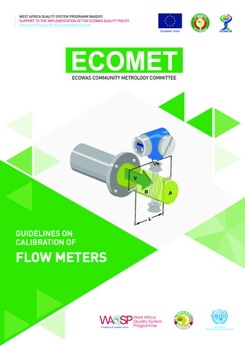
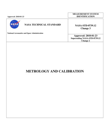
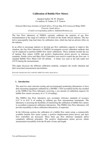
Measurement Deviation Results and MeasurementUncertantiesRef-UUT 40005000Nominal Reading (ml/min)Figure 2. Measurement results deviations and measurement uncertainties for the calibrationof a bubble flow meter against the laminar flow meters (LFM), the positive displacementpiston prover (PD) and the mass flow controllers (MFC).In figure 2, the measurement results and their associated uncertainties for the threecalibration procedures are graphically presented. The results show better agreementbetween the calibration of the bubble flow meter against the piston prover and against thelaminar flow meters at flow rates higher than 10 % of full scale of the unit under test.The calibration against the mass flow controllers showed a larger corrections andmeasurement uncertainties as compared to the other two methods.This large uncertainty associated with the calibration against the mass flow controllers islargely due to the expanded uncertainty of the mass flow controllers which is at least fourtimes that of the piston prover and that the laminar flow meters. The inaccuracy observedin the lower 10 % of full scale of the bubble flow meter can be attributed to the difficultyof measuring low flow rates. At low flow rates gas leaks are very difficult to detect andthey can contribute significantly to measurement errors. Other sources of error could bethe waving of the soap film as it ascends and the perturbation of flow profile as thereference standard’s piston returns to the bottom of the flow tube. It was noticed at someflow rates that the falling of the piston slightly changed the shape of the soap filmmeniscus. The waving of the soap film and changing of the meniscus may also havedegraded the reading repeatability of the bubble flow meter.8. ConclusionThe NMISA Gas Flow laboratory calibrated a bubble flow meter with threecommercially available gas flow reference standards utilizing completely differentoperating principles.The results obtained indicated good agreement of the first two methods with mostmeasurement uncertainties less than 0,7 % of reading. However, the measurementTest and Measurement Conference
uncertainty for the calibration of the bubble flow meter against the mass flow controllerswas observed to be higher, at least 0,9 % of reading.It is concluded that, for mass flow controllers to be used as reference standards, theyrequire tighter accuracy specifications and lower measurement uncertainty. Therefore,the mass flow controllers used for this project to calibrate instruments with 1 % accuracy specifications are not suitable for use as reference standards due to theirhigh expanded uncertainties.Note: Any commercial product/instrument mentioned does not represent an endorsementbut is for the purpose of identifying the product/instrument used.References1.M. Adkins, “Matching valve type to function: A tutorial in valve selection.”, June2011, pages 49 to 55.2.J. Tesar, D. Prazak, and Z. Krajicek, “The New CMI (Czech Metrology Institute)Method of Metrological Ensure for Accurate Mass Flow”, Analytical Sciences,August 2001, Vol. 17, pages 1399 to 1402.3.J. G. Olin, and D. M. Korpl, “Achieving Accurate Gas Flowmeter Calibration”,NCSL Workshop & Symposium, Washington DC., USA, August 1992, pages 435 to441.4.Mesa Labs, “Bios DryCal Technology”, user manual.5.T. Kagawa, Y. Saisu, R. Nishimura, and C. Youn, “Development of High SpeedResponse Laminar Flow Meter for Air Conditioning”, 10th International Conferenceon Fluid Control, Measurements, and Visualization, Moscow, Russia, August 2009,pages 1 to 10.6.R. Siev, B. G. Liptak, and J. B. Arant, “Instrument Engineers’ Handbook: ProcessMeasurement and Analysis”, 1995, CRC Press, 0-8493-1083-0 (v. 1).Test and Measurement Conference
upstream of the bubble flow meter to avoid contamination. The system was pressurized to 200 kPa at a flow rate of 2500 sccm (standard cubic centimetre per minute) and leak checks were performed using a liquid leak detector. The bubble flow meter was then calibrated against two flow cells in the flow ranges 0,5 sccm to