Transcription
High-Turnaround and Flexibility in Design and Construction of Mass HousingHIGH-TURNAROUND AND FLEXIBILITY IN DESIGNAND CONSTRUCTION OF MASS HOUSINGAmarjit Singh1, Rick Barnes2, and Ali Yousefpour3ABSTRACTThere is a tremendous housing shortage in the world that can only be overcome byinnovative designs and enlightened production management. This paper presents a methodfor fast erection of apartment housing units that have architectural flexibility, manufacturingflexibility, and erection flexibility. The paper describes innovative jointing methods for largepanel erection and presents characteristics of an appropriate structural system to correspondto the mechanical jointing and quick erection needs. Erection speeds using this method areabout ten times as fast as conventional methods. Details of erection requirements andequipment are given.KEY WORDSFlexibility, architecture, production, joint, precast, industrial housing, mass housing,prefabrication, structure, throughput, erection, manufacture, FMS, construction.123Associate Professor, Department of Civil Engineering, University of Hawaii at Manoa,Honolulu, HI 96822. 808/956-3933, fax: 808/956-5014, singh@wiliki.eng.hawaii.eduResearch Assistant, Department of Civil Engineering, University of Hawaii at Manoa,Honolulu, HI 96822.Research Assistant, Department of Mechanical Engineering, University of Hawaii atManoa, Honolulu, HI 96822.Proceedings IGLC-7181
Singh, Barnes, and YousefpourINTRODUCTIONQuality housing is in short supply in the world. It is estimated that the world is short of 200million dwelling units. To overcome this shortage within a reasonable time is not easy. Evenconsidering that 100 years might be a reasonable enough time frame for this mammoth task,each dwelling unit will have to be delivered at the rate of 3.74 seconds during a normal 40hour workweek. The non-delivery of adequate quality housing at a stage and time of theworld’s evolution when human population is expected to double within the next twenty yearsdoes not bode well for social and political well being. To address this challenge requiresunconventional and innovative methods of housing construction. Only modern methods ofhousing manufacture and erection, utilizing principles such as computer integratedmanufacturing (CIM), flexible manufacturing systems (FMS), and lean manufacturingcoupled with innovative ideas can hope to erect houses at fast speed and high throughput.The cam-nut and cam-screw method of joining large panels was explored for furtherdevelopment (Singh 1998, Singh and Yousefpour 1998). Tests revealed that this jointingmethod is adequate to carry all design loads. Structural testing indicated that structuraladequacy could be assured if structural homogeneity could be assured. Finally, analysis wasundertaken to determine how best to optimize construction speed within the technologicalconstraints posed by large panel manufacture and erection for mass housing.The prescribed cam-nut and cam-screw method furthers the principles and objectives offlexible and lean construction.OBJECTIVESThe objectives are simply to design manufacturing and erection methods that are fast andcost-effective for mass housing. This further entails reduced waste, product innovation, andagile production.RESEARCH METHODOLOGYThe following research methodology was followed:1. Literature survey2. Idea brainstorming3. Selection of viable construction systems and technologies4. Mechanical joint analysis and design5. Structural analysis and design6. Equipment and cost estimate7. Erection and construction analysisSCOPEThe scope of work is limited to establishing conceptual framework and conducting basiccalculations for analysis, design, and cost for the erection of prefabricated large panels. Thefocus is primarily on obtaining high erection speeds on the job site, assuming that high largepanel production will be available from the factory. Another limiting scope of this project isthe use solely of concrete for housing units. The reason for using concrete is that concrete18226-28 July 1999, University of California, Berkeley, CA, USA
High-Turnaround and Flexibility in Design and Construction of Mass Housingingredients are less limited in their world supply than are steel ingredients. For mass housing,then, it is rationale to use a world resource that is more abundant.The focus is also on the structural elements – the building shell. Items such as plumbing,electricity are excluded from this paper. The use of finishes in construction is minimized oreliminated through adequate finishing provided at the manufacturing shop. Emphasis is laidon explaining the application and furtherance of lean principles to the product.FLEXIBILITY IN HOUSINGWhereas mass production is known to have economies of scale, there are certain bottleneckswhen it comes to prefabricated housing. For mass housing to be an attractive option, it isessential to provide architectural flexibility wherein each new dwelling complex can be ofdifferent design, thereby avoiding architectural monotony. This is equivalent to havingproduct variety (Bessant 1991, Barlow 1998). Under flexible manufacturing systems, welearn that production systems should have the following flexibilities in our stated projectamong other general manufacturing flexibilities (Browne 1984, Singh and Talavage 1991). process flexibility, mix flexibility, volume flexibility, routing flexibility, and machine flexibilityFor our project, mix flexibility is related to architectural flexibility (e.g., a production plant iscapable of manufacturing panels of different sizes and shapes on demand). Process flexibilityis related to having multiple stations in a production plant that can perform identical andmultiple operations for the purpose of quick turnaround. Volume flexibility relates to thecapability of increasing and lowering production volume at short notice. Routing flexibilityrelates to the (automatic) ability to route a part (panel) to another station in case one or theother is busy. Finally, machine flexibility is related to machine reliability (Singh 1995).Volume flexibility for mass housing is equally important on the job-site as it is in thefactory for mass production. Job-site volume flexibility can be enhanced by innovativedesign that assists in quick erection. Thus, innovative design becomes very important to us inachieving our ends of high-speed mass housing. In addition, flexibility is closely related tolean and agile production, since many of their guiding principles and philosophies areidentical. Importantly, the idea of flexibility to reduce setup time through repetitiveness is ofparticular application in this study.LEAN PRODUCTION APPLIED TO CONSTRUCTIONIt is notable that Slack (1997) has not defined the term “lean manufacturing” or “leanproduction” in his Encyclopedia of Manufacturing. This sends the signal – probablyerroneous -- that “lean” is not a popular term among the industrial engineers and that otherterms, such as group technology, flexible manufacturing, and computer integration arepreferred. However, this is not to minimize the application of “lean”, since it is well knownthat the Toyota miracle owes much to the lean principles of Ohno, where he reduced wasteand inventory at every opportunity in a scientific and organized manner (Delbridge 1998).Proceedings IGLC-7183
Singh, Barnes, and YousefpourEssential production principles applied to lean construction include productionparameters such as the following (Andery et al. 1998, Brandon 1995, Gowda, et al. 1998,Howell and Ballard 1998, Isatto and Formosa 1998, Singh and Ebeling 1995, Smook 1996,Warnecke and Steinhilper 1985): avoiding waste, standardization of repetitive work, creating a uniquely custom product, reduction of resource idleness, reduction of average waiting time, reduction of time between delivery of finished products, reduction of variability, decrease in time for processing parts to traverse the system, decrease in costs, reducing inventory, and increase in production rate.It is frequently observed that above parameters are interrelated. Thus, it is important to tackleproduction at a holistic level where all above parameters are sought to be optimized(Warnecke and Steinhilper 1985, Singh and Skibniewski 1991).The reduction of waiting time and resource idleness can be overcome by assuring thatcrews move in parallel for erection and grouting activities. Decrease in time for processingparts is assured by using the innovative methods developed herein and by assuring that crewsare occupied through low resource idleness. Collectively, the above assure high productionrate, and cost reduction occurs due to economies in mass construction.INNOVATION FOR LEAN PRODUCTIONContinuous improvement is a hallmark to the way in which lean principles can be applied toany production process (see Andery et al. 1998). With improvement, waste in time, material,and money can be reduced, thereby contributing to efficient lean production. In addition,innovation contributes the same way as improvement. Indeed, innovation is essential for leanproduction (Martin and Formoso 1998, Malhedo 1998), since innovation has thecharacteristic of streamlining work flow— either through innovative design or throughinnovative task planning— it assists in the enhancement of lean principles.Mass manufacture is known to assist with lean production. However, mass prefabricationhas hitherto had the drawback of reduced product variety and reduced agility (Bessant 1991,Baker 1996, Burgess 1994). With architectural flexibility, the innovative production methoddeveloped in this paper is enhanced, thereby contributing to agile production.INDUSTRIALIZED PRODUCTION AS CENTRAL THEMEWhereas the successes of industrialized housing is well known in Scandinavia, Finland inparticular, and also in East Asia where Singapore is a prime example, it is desired to simplifysite erection by reducing the number of parts that are required to fulfill a whole building.18426-28 July 1999, University of California, Berkeley, CA, USA
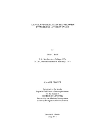
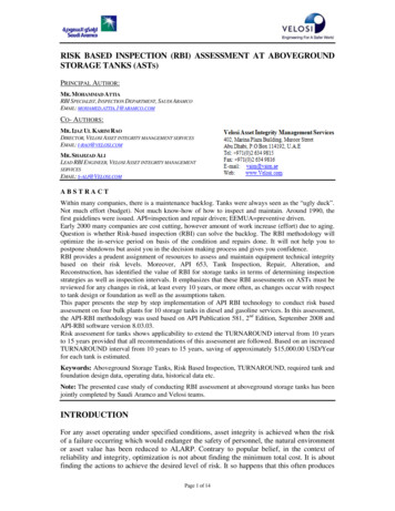
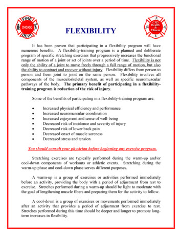
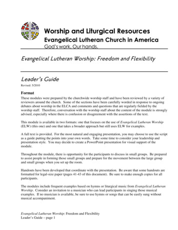
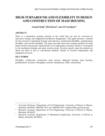
High-Turnaround and Flexibility in Design and Construction of Mass HousingThough buildings can be erected with columns, beams, slabs, and walls, the erection issimplified in our proposal through only the use of large panels.LEAN CHARACTERISTICS OF PROPOSED PREFAB SYSTEMThe developed system using fully embedded cam-nut/cam-screw for joining concretecomponents allows immense repetition of work tasks for shell erection that can beundertaken using a single crew. Consequently, set-up time between activities is minimizedand there is continuity to the process. In addition, after optimal speeds through learning arereached, those speeds can be sustained since there is no change of activity for construction ofthe mass housing. Again, management coordination is easier, since fewer subcontractorsmust be coordinated; there are fewer workers on site; and fewer number of differentactivities. Since the number of type of products required for shell erection is brought down tounity, there are fewer inventory categories.In addition, the proposed system is a unique custom product. The design, too, isconducive to simplified workflow. Finally, the time to erect and cost to construct aresignificantly lower, which are the ultimate objectives in many a production system.ARCHITECTURAL CHARACTERISTICSThe basic general architectural plan proposed consists of a 2,815 square foot floor plan,Figure 1. Various other basic general plans can also be proposed. The proposed unit has onethree, one two, and two one-bedroom units, or modules. This basic layout can be configuredto develop larger building units; thus, there is in-built architectural flexibility. The modulescan be placed in different locations to meet various needs. These modules are standardized toallow for efficient manufacture, but still have flexibility in their layout, providing manypossible floor plans. An axonometric for the basic configuration is given in Figure 2. Otherconfigurations based on different combinations of the modules of Figures 1 and 2 areprovided in Singh (1998).A maximum story height of seven stories has been set, motivated primarily by thefollowing factors: Building design and fire codes are less constrictive for buildings of seven storiesor less. Site erection is simplified since tower cranes are not required. Construction costs rise significantly for buildings more than seven stories.MECHANICAL CHARACTERISTICS OF CAM-NUT AND CAM-SCREWErection of the multi-story building using conventional methods is a time consuming task.Having the mechanical joint such as cam-nut/cam-screw for the assembly of walls, floors andcolumns can increase the speed and quality of construction compared to that of theconventional methods. The cost of erection of multi-story building using the cam-nut/camscrew mechanical joint is much less than those using conventional methods. This is madepossible due to ease of assembly of the components and correspondingly less use of labor.Proceedings IGLC-7185
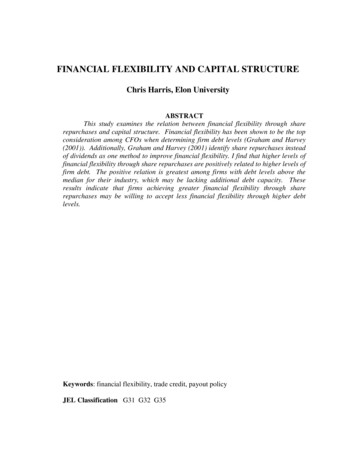
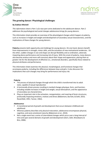
Singh, Barnes, and YousefpourFigure 1: General Plan LayoutBefore selecting the cam-nut/cam screw, several mechanical joint types such as bolt and nut,and welded joint were studied. The cam-nut/cam-screw was chosen due to better mechanicalperformance and faster assembly opportunities than other methods (Singh 1998).Figures 3 and 4 show the schematic of cam-nut/cam-screw at loose and tightenedpositions. The cam-nut is embedded in the panel and the cam-screw is attached to the side ofthe adjoining panel. The joint was designed in such a way that as the two panels assemble,the cam-screw is inserted in the cavity inside the cam-nut; the cam-nut is then tightened18626-28 July 1999, University of California, Berkeley, CA, USA
High-Turnaround and Flexibility in Design and Construction of Mass HousingFigure 2: Axonometric Viewusing pneumatic or electrical power tools. The cavity inside the cam-nut is designed in a waythat as the cam-nut is tightened, it pulls the cam-screw inside.Since the panels have protruding screws, there are limitations to how the panels may beconnected to each other. In addition, as it is expected that the architect will exercise hisprivilege of design flexibility, different types of panels, having varied loading conditions willbe produced. Some of these panels may be having protruding screws on all sides, others onsome sides only, and so on.To accommodate this difficulty in joining panels when their protruding screws may comein the way, there are two essential erection scenarios (see Figures 5 and 6). The fundamentalneed to remedy this difficulty is to design “pockets” in the concrete that can receive thescrews before the screws are slipped into nuts.Cam-screwCam-nutFigure 3: Joint at Loose PositionProceedings IGLC-7Cam-screwCam-nutFigure 4: Joint at Tightened Position187
Singh, Barnes, and YousefpourSTRUCTURAL CHARACTERISTICSVertical JointPocketVertical JointThe building system is an all panel system. Buildings are made up of wall panels and floorpanels, or slabs. The use of one structural element eliminates beams and columns. Thisgreatly simplifies the design and manufacture process.PocketHorizontal JointCam-screwCam-nutCam-screwCam-NutHorizontal JointFigure 5: Panels with ProtrudingCam-Screws at all SidesFigure 6: Panels with Cam-Nuts andProtruding Cam-ScrewsThe panels consist of a 6’ thick structural section, a 1.5” thick insulation section and a 2.5”thick facade section. The panels are joined with mechanical joints along the panel’s verticaland horizontal edges. The mechanical joints clamp the panels together with sufficient force toallow them to work together as a monolithic element. A gasket is placed between each paneland between the panels and the floor slabs to ensure a weather tight seal.The floor system consists of solid precast floor slabs, designed as one-way slabs (Figure7). These slabs lie on top of the wall panels and are held in place by passing the cam-screw ofthe lower wall panel through the floor slab and into the upper wall panel. This clamps thefloor slab in place. Solid slabs were used because they can tolerate the expansion andcracking problems, whereas precast hollow core slabs would not be able to. The wall panelsprovide bearing for the gravity loads and the cam-screw provides bearing for lateral rmfCam-screw pass throughholesFloor slabOverlapjointFigure 7: Floor Slab18826-28 July 1999, University of California, Berkeley, CA, USA
High-Turnaround and Flexibility in Design and Construction of Mass HousingAlong the sides, the slabs overlap each other, allowing for a more continuous floor system.These joints are beveled to allow an epoxy grout to be placed between each slab to seal thejoints and provide a flatter continuous floor.ADEQUACY OF CAM-NUT/CAM-SCREWThe cam-nut/cam-screw was designed using finite element analysis (Singh and Yousefpour1998). ANSYS finite element software was used. Design constraints for the mechanical jointwere i) the size of the panel, ii) the amount of distribution of reinforcement, iii) the appliedloads on the joint, and iv) the material of the joint.The load was distributed on the three mechanical joints which are located at horizontaland vertical sides of the wall or floor-panels to connect one wall or floor-panel to adjacentwall-panels or columns. The loads applied on each joint located at the horizontal and verticalsides of panels at each level were taken from the ETABS output (Singh and Barnes 1999).The joint can be made of AISI 1030 steel, a conventional material (Shigley and Mischke1989). The results of finite element analysis (FEA) revealed that the maximum stress of thecam-nut and cam-screw for both vertical and horizontal joints was 12,341 psi and 8,865 psi,respectively. The stress factor of safety of 4.1 and 5.6, respectively, were achieved, for theyield strength of 50,000 psi. The cam-nut dimensions were 6”φ and 4.5” thk. The cam-screwdimensions were 4” at the end and 3” at the tip, by 9.4” in length. The same cam-nut as usedin the horizontal and vertical joints can be used for a vertical joint between walls through aslab, since the loads are identical and cam-nut sizes are practically the same. The length ofthe cam-screw is 6” (thickness of the panel) longer than the cam-screw from the horizontaland vertical joints. The results of FEA revealed that the maximum stress of the cam-nut andcam-screw was 12,341 psi and 14,860 psi, respectively. The minimum stress factor of safetyof 3.4 was achieved, for the yield strength of 50,000 psi. This high factor of safety isadequate for this critical mechanical structure.STRUCTURAL ADEQUACYIn order for the panels and mechanical joints to be designed, the maximum loads that thepanels and joints would be subjected to have to be determined. The building was analyzed forboth earthquake and wind loads, with the larger of the two being used, following the UniformBuilding Code, UBC. Computer structural analysis was performed using a special-purposeFEA program for building analysis, ETABS (Singh and Barnes 1999). Output from ETABSprovided the necessary axial, shear, and moment loads on the panels. These loads were usedto design the panels and the mechanical joints.In order for the mechanical joints to work with the wall panels, they must be adequatelyanchored to the panels. To do this a system of steel plates and headed studs were designed.The cam-nuts and cam-screws are welded to a plate and long studs attached to the plate.These studs are embedded in the concrete during the casting of the wall panels.JOINTING NEEDSThe cam-nut/cam-screw can be fastened using a pneumatic or electrical power tool. Theamount of torque required to rotate the cam-screw about 190 degrees in order to sit into atightened “click position” can be measured experimentally. However, commercially availableProceedings IGLC-7189
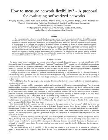
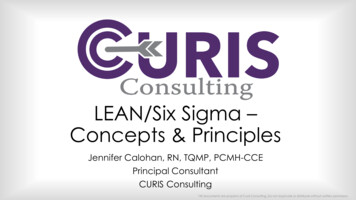
Singh, Barnes, and Yousefpourpower tools are available with large sized screw bits to execute the work. A crew of twoworkers is required to move in parallel alongside the panel erection to tighten the nuts.ERECTION SEQUENCINGThe erection sequence of the panels is crucial in the construction process. Although there isgreat flexibility in the erection process, there are still critical considerations to be followed.The biggest concern is the location of the pockets in the panels to accommodate protrudingscrews. The pockets along the horizontal sides (Figures 5 and 6), are on either side of thecam-nuts; thus, the panels can only slide in one direction. This is one of the controllingfactors in the erection sequence. Great care must be made in ensuring the proper sequence ofpanel assembly is followed.It is best to start construction assembly at one of the outside corners. This provides for thestiffest structure as the building is erected. No one outside corner is critical, so any outsidecorner may be picked. This allows for flexibility in the erection sequence. To accommodatethe pocket system, work out from one corner in both directions, bringing the subsequentpanels up against the installed one. As each panel is placed, the cam-nuts can be tightened.The slabs are installed after the panels are in place. The slabs are placed on top of thepanels and the cam-screws pass through the slab. Slabs may be placed before all the panelshave been erected. The only factor controlling this is to ensure that all the panels that arebelow the slabs are in place.The entire erection sequence will be fastest if following a predetermined sequence. Thisis not always possible though. Many circumstances may be unforeseen. If all the panels donot arrive at the site, or some become damaged during transit, erection does not have to stop.Although there are a few critical panels, erection can start at any outside corner withwhatever panels arrive first. If during the construction the next needed panel is damaged ornot available, erection may start at a different area. Since all the panels do not have to beerected for the slabs to be placed, the erection sequence is not entirely dependent on all thepanels being erected first. This affords considerable erection flexibility.Figure 8 shows the layout of the structural panels. There are 33 wall panels numbered onethrough 33 and 13 slabs labeled A through M. After panels 1 through 12 have been erected,for instance, slabs A, B, and C can be placed. This allows yet more flexibility in the erectionsequence. Slabs can be erected on the finished panels while any missing panels are beingreplaced. This prevents any waiting time and resource idleness in the construction process.Table 1 shows four options for erecting the panels; all options start from the corner ofpanels 2 and 3, Figure 8. Options 1 and 2 simply start from one corner and move counterclockwise to complete the erection sequence, with slight differences between them.Table 1: Erection Sequence AlternativesOPTIONOption 1Option 2Option 3Option 2511112926121228271314272814132629PANEL NUMBER15 16 17 18 19 2015 16 17 33 23 1825 24 22 8 9 1030 31 32 8 9 32333326-28 July 1999, University of California, Berkeley, CA, USA
High-Turnaround and Flexibility in Design and Construction of Mass HousingOptions 3 and 4 start at the same corner but stop at panel 7. Option 3 starts up again withpanel 31 proceeding through panel 22, then moving to panel 8 to finish the sequence. Option4 switches to panel 22 proceeding through panel 32, then moving to panel 8 to finish thesequence. This shows how flexible the erection sequence can be.Numbers represent panelsLetters represent slabs- represent cam-screwso represent cam-nutsFigure 8: Panel and Slab LayoutTRANSPORTATION OF PANELSThe size of the panels and slabs are limited by the transportation used to deliver them. Bylimiting the lengths of the panels and slabs to under 40 feet and the widths to under 10 feet,standard trailers can be used. Larger size panels and slabs may be used but special permittingand routing to the construction site may be needed, adding to the cost of construction.Coordinating delivery so that the panels arrive as they are erected adds to efficiency, butbecause of the flexibility of this system this is not critical.POCKET GROUTINGAll pockets must be grouted after installation. For the general plan, there are 113 pockets perfloor and 188 cam-nuts per floor. The pockets are grouted by pressure injecting grout throughProceedings IGLC-7191
Singh, Barnes, and Yousefpoursmall access holes. The grout gun injects the grout through the hole and the hole is pluggedwith a plastic slug. The grouting can be done as the panels are installed. The grout would benon-shrinking and pumped or pressure injected. Using a pneumatic, shoulder carried groutpump, a crew of four can grout approximately five floors per day (Means 1997).SLAB JOINT GROUTINGThe slabs overlap one another along their long axis. This joint is beveled, has exposedreinforcing, and is filled with epoxy-grout. The exposed reinforcing along with the epoxygrout ties the slabs together, providing a stiff diaphragm. The epoxy grouting also smoothesthe transition between the slabs. This system eliminates the need for cast in place concreteover the entire slab area. Using a grout pump, a crew four can finish approximately fivefloors per day (Means 1997).EVALUATION OF TECHNOLOGYVarious techniques for evaluating construction and building technologies usingmanufacturing principles have been provided in literature through mathematical precepts(Singh and Ebeling 1994, Martin and Formoso 1998). An evaluation of the proposed systemcan be made after a complete process simulation is executed (for instance, refer Singh andTalavage 1991, Gowda et al. 1998).TIME AND COST ESTIMATES FOR LARGE PANEL ERECTIONErection costs are dramatically reduced since construction durations are reduced by nearlyten times. Prefabrication is currently more economic than conventional construction forresidential apartment complexes in many world locations, such as Finland and Singapore, forexample. This means that with industrial conversion and mass consumption, the economiesof industrialized building can be well exploited.Four panels can be erected per hour with crane and four-man crew. Therefore, it wouldtake 1.5 days to erect the 46 panels for the entire floor. (These results are based on estimatesof prefab construction from site data, expanded application of learning curves, and MeansManual.) In contrast, conventional construction can take from 10 to 20 days to finish a flooron site, which is 670% to 1330% longer than in the proposed prefab construction.A 7-story building will take approximately 11 days to finish; traditional constructionwould take 105 days. Extending this arithmetic further, the panel system can build nine fullbuildings in the amount of time it takes traditional construction to build one building.Working 250 days a year, one crew can erect 22 such buildings having 616 housing units;traditional construction would have constructed only 2 buildings or 56 housing units. With100 crews, 61,600 housing units can be built in one year.Therefore, the construction time is approximately ten times as fast as conventionalconstruction. Conventional construction can take from10 to 20 days to cast a complete floor.Correspondingly, erection costs are dramatically reduced since construction durations arereduced by an average of ten times.With the flexibility of the system, costs can be further reduced. In traditional constructioneach sequence of construction, such as formwork or pouring concrete, stops or dramaticallyslows the work of others. Walls for each story must wait until the entire slab of that story is19226-28 July 1999, University of California, Berkeley, CA, USA
High-Turnaround and Flexibility in Design and Construction of Mass Housingcomplete. With the panel system, walls of the next story can be erected before all the slabs ofcurrent story are complete. This means that there is less conflict in scheduling the work crew.With this system in particular, the pocket grouting crew does not have to wait for all thepanels to be in place for one floor to start grouting. Once a few panels are in place, they canbegin grouting.Pocket grouting requires a shoulder carried grouting gun. The pockets to be filled are7”x7”x4” or 0.111CF. There are 113 pockets per floor with this typical building, giving12.45 CF of grouting per floor. Taking the assistance of Means (1997), we estimate that onegrouting labor, one equipment operator and one helper can grout approximately 70 CF perday. Thus, they can do five floors per day. Floor grouting for the longitudinal constructionjoints of slabs can be done at similar speeds.Both nut tightening and pocket grouting are faster work activities per panel in contrast topanel erection. Nut tightening involves only the mechanical tightening of the nut, which canbe done by a two-man crew.CONCLUSIONSThe following major conclusions are derived: The cam-nut/cam-screw mechanical jointing method is mechanically andstructurally feasible. Architectural flexibility, i.e., product variety, is ensured. The cam-nut/cam-screw joint can increase the speed and quality of construction. Production agility is increased. The success of this system will depend on the production of large panels underfactory conditions, produced at high speed using lean construction, flexiblemanufacturing, and improved production management principles.REFERENCESAndery, P., Carvalho, A. N., and Helman, H. (1998). “Looking for What Could be Wrong:An Approach to Lean Thinking.” Proc. 6th Ann. Conf. Intl. Group Lean Constr., Guaruja,Brazil, 13-15 Aug.ANSYS User’s Manual (1994). Revision 5.2, ANSYS, Inc. Houston, PA.Baker, J. (1998). “Less Lean but Cons
7. Erection and construction analysis SCOPE The scope of work is limited to establishing conceptual framework and conducting basic calculations for analysis, design, and cost for the erection of prefabricated large panels. The focus is primarily on obtaining high erection